EP0015976B1 - Electric heater assembly for diffusion pumps - Google Patents
Electric heater assembly for diffusion pumps Download PDFInfo
- Publication number
- EP0015976B1 EP0015976B1 EP79900465A EP79900465A EP0015976B1 EP 0015976 B1 EP0015976 B1 EP 0015976B1 EP 79900465 A EP79900465 A EP 79900465A EP 79900465 A EP79900465 A EP 79900465A EP 0015976 B1 EP0015976 B1 EP 0015976B1
- Authority
- EP
- European Patent Office
- Prior art keywords
- sheath
- plate
- heater
- contact
- face
- Prior art date
- Legal status (The legal status is an assumption and is not a legal conclusion. Google has not performed a legal analysis and makes no representation as to the accuracy of the status listed.)
- Expired
Links
- 238000009792 diffusion process Methods 0.000 title claims abstract description 21
- 229910052751 metal Inorganic materials 0.000 claims abstract description 20
- 239000002184 metal Substances 0.000 claims abstract description 20
- 239000012530 fluid Substances 0.000 claims abstract description 9
- 238000013021 overheating Methods 0.000 claims abstract description 9
- 230000000712 assembly Effects 0.000 claims abstract 2
- 238000000429 assembly Methods 0.000 claims abstract 2
- 238000013016 damping Methods 0.000 claims 1
- 230000008016 vaporization Effects 0.000 claims 1
- PXHVJJICTQNCMI-UHFFFAOYSA-N Nickel Chemical compound [Ni] PXHVJJICTQNCMI-UHFFFAOYSA-N 0.000 description 4
- 238000010438 heat treatment Methods 0.000 description 3
- 229910001026 inconel Inorganic materials 0.000 description 3
- 238000001816 cooling Methods 0.000 description 2
- 239000007788 liquid Substances 0.000 description 2
- CPLXHLVBOLITMK-UHFFFAOYSA-N magnesium oxide Inorganic materials [Mg]=O CPLXHLVBOLITMK-UHFFFAOYSA-N 0.000 description 2
- 239000000395 magnesium oxide Substances 0.000 description 2
- AXZKOIWUVFPNLO-UHFFFAOYSA-N magnesium;oxygen(2-) Chemical compound [O-2].[Mg+2] AXZKOIWUVFPNLO-UHFFFAOYSA-N 0.000 description 2
- 238000004519 manufacturing process Methods 0.000 description 2
- 239000000463 material Substances 0.000 description 2
- 229910001120 nichrome Inorganic materials 0.000 description 2
- 229910052759 nickel Inorganic materials 0.000 description 2
- 229910000831 Steel Inorganic materials 0.000 description 1
- 229910045601 alloy Inorganic materials 0.000 description 1
- 239000000956 alloy Substances 0.000 description 1
- 230000015572 biosynthetic process Effects 0.000 description 1
- 230000000994 depressogenic effect Effects 0.000 description 1
- 230000006866 deterioration Effects 0.000 description 1
- 238000010586 diagram Methods 0.000 description 1
- -1 e.g. Substances 0.000 description 1
- 239000012777 electrically insulating material Substances 0.000 description 1
- 230000005484 gravity Effects 0.000 description 1
- 229910001385 heavy metal Inorganic materials 0.000 description 1
- 210000002445 nipple Anatomy 0.000 description 1
- 239000000615 nonconductor Substances 0.000 description 1
- 230000002093 peripheral effect Effects 0.000 description 1
- 239000000843 powder Substances 0.000 description 1
- 230000005855 radiation Effects 0.000 description 1
- 239000010935 stainless steel Substances 0.000 description 1
- 229910001220 stainless steel Inorganic materials 0.000 description 1
- 239000010959 steel Substances 0.000 description 1
- 239000002470 thermal conductor Substances 0.000 description 1
Images


Classifications
-
- H—ELECTRICITY
- H05—ELECTRIC TECHNIQUES NOT OTHERWISE PROVIDED FOR
- H05B—ELECTRIC HEATING; ELECTRIC LIGHT SOURCES NOT OTHERWISE PROVIDED FOR; CIRCUIT ARRANGEMENTS FOR ELECTRIC LIGHT SOURCES, IN GENERAL
- H05B3/00—Ohmic-resistance heating
- H05B3/78—Heating arrangements specially adapted for immersion heating
- H05B3/82—Fixedly-mounted immersion heaters
-
- F—MECHANICAL ENGINEERING; LIGHTING; HEATING; WEAPONS; BLASTING
- F04—POSITIVE - DISPLACEMENT MACHINES FOR LIQUIDS; PUMPS FOR LIQUIDS OR ELASTIC FLUIDS
- F04F—PUMPING OF FLUID BY DIRECT CONTACT OF ANOTHER FLUID OR BY USING INERTIA OF FLUID TO BE PUMPED; SIPHONS
- F04F9/00—Diffusion pumps
Definitions
- the present invention relates generally to electric heaters, and more particularly, to an electric heater wherein a tubular electric heater having a tubular sheath has one side thereof in contact with raised portions of a thin, flexible metal plate.
- Diffusion pumps include a pool of oil that is vaporized in a boiler usually by a high watt density (e.g., 225 watts/cm 2 ) electric heater.
- a high watt density e.g., 225 watts/cm 2
- One prior art diffusion pump boiler includes a tubular electric heater which has been swaged into a groove in a steel platen. Heat is transferred from the tubular heater to the platen and to a flat contacting side of a metal plate which constitutes the boiler plate of the diffusion pump. Heat propagates through the platen to a flat face of a heavy metal boiler plate and then to the opposing face that forms a floor for the pool so that heat is transferred directly from the plate to the pool.
- the electric heater typically comprises a metal tubular sheath, usually formed of Inconel, that surrounds a spiral filament, formed usually of Nichrome.
- a space between the filament and the interior surface of the sheath is filled with a material which is bcth an electrical insulator and a thermal conductor, e.g., magnesium oxide.
- Terminals on each end of the sheath are usually threaded nickel rods welded to the ends of the filament and brought out past the ends of the sheath so that lead wires may be connected to them.
- These tubular heaters are easily formed into various configurations, such as circles, helices and spirals.
- the high watt density tubular heaters of diffusion pumps must be thermally loaded to such an extent that the heat loss from the sheath keeps all exterior sheath portions below about 750°C. Sheath temperatures in excess of about 750°C cause rapid deterioration and, hence, short life of the heater.
- a typical heater shape might be a 120° sector.
- the configuration of the tubular heating element within the boundaries of the sector is designed in such a way that it has a maximum length. In this way the watt density is kept as low as possible. It would seem that if the heater were sandwiched tightly between the boiler plate and a flat. heavy clamping plate, that the side of the entire length of the heating element facing the boiler plate would be in contact with it. I have found this is not the case.
- the diameter of the heater sheath may have gradual variations along its length of about ⁇ .0375 cm from the mean diameter.
- the heater sheath makes firm contact with the boiler plate only where the diameter is at a maximum.
- the transfer of heat must be accomplished by convection and radiation which is much less efficient than conduction.
- the temperature of the heater may become excessive at the regions where there is no contact, regions referred to as hot spots.
- British patent specification 1285042 discloses an electric heater assembly particularly adapted to heat a flat bottom surface of the boiler plate suitable for a pool of vaporisable diffusion pump fluid and comprising a tubular electric heater having a tubular sheath, said tubular heater being adapted to be energised so that it has a tendency to be overheated if only air is its thermal load, a first side of said sheath being adapted to contact the flat surface of the boiler plate, a thin flexible metal crush plate in contact with a second side of the sheath, the second side being opposite from the first side of the sheath and means for urging the sheath into contact with the flat surface of the boiler plate.
- the urging means does not load the tubular electric heater sufficiently along its length so that substantial portions of its length are not contacted by a relatively high thermal load, the heater has a tendency to develop hot spots which may reduce its life.
- a more uniform loading is achieved according to the present invention wherein the flexible metal crush plate has raised and spaced segments, said segments crossing the second side of said sheath so that the longitudinal axes of the sheath and the segments are non-aligned at intersections between the sheath and the segments, a heavy flat plate abutting against the face of the thin plate opposite from the face from which the segments extend, said urging means urging the heavy plate against the thin plate towards the tubular heater so that the segments are deformed and pressed against the second side of the sheath, said segments being urged against the tubular sheath by the heavy plate.
- These segments are typically spaced 5 to 7.5 cm apart.
- the segments are deformed whenever they are in contact with the heater sheath.
- the amount of deformation depends upon the sheath diameter at the point of contact.
- the deformed segments urge virtually the entire length of the sheath into contact with the boiler plate. Although the amount of deformation varies at each point of contact, the deformation insures that pressure is applied to the heater shell at the point of contact. Since there are many points of contact, the occurrence of local overheating, i.e., hot spots, is virtually eliminated.
- a diffusion pump including an electric heater assembly 10 in accordance with the invention.
- the diffusion pump includes a cylindrical exterior wall 11 that is wrapped by a spiral cooling coil 12. Secured to the bottom of cylinder 11 is a relatively massive metal boiler plate 13, having an upper face 14 that forms a floor for pool 15 of vaporizable diffusion pump fluid or oil. Lower face 16 of plate 13 contacts a first surface of a coil-like tubular electric heater or heating element 17, having a second side that contacts thin, flexible metal crush plate 18, which in turn abuts against a second relatively massive metal plate 19.
- Vapor from pool 15 flows to a series of concentric diffusion pump nozzles 25-27 and to an ejector nozzle 28.
- the vapor flowing from nozzles 25-27 traps molecules from a high vacuum load connected to flange 24 and is condensed on the interior surface of cylinder 11..
- the condensed vapor on cylinder 11 flows, by gravity, back to pool 15 along the walls of the cylinder, in a manner well-known to those skilled in the art.
- In line with ejector nozzle 28 is a tapered, horizontally extending tube 29, also wrapped with a cooling coil 30.
- In fluid flow relationship with tube 29 is foreline 31, connected to a foreline pump in a manner well-known to those skilled in the art.
- tubular electric heater 17 of heater assembly 10 includes a tubular, generally circular cross-section sheath 33, preferably having flat upper and lower faces.
- Sheath 33 is made of a suitable, relatively temperature stable metal, such as the alloy Inconel, and is formed as a flat convoluted sector having a relatively long total length.
- a resistive heater coil 34 preferably fabricated of Nichrome.
- an electrically insulating material having high thermal conductivity such as magnesium oxide powder 35.
- Electric heaters having these properties are generally commercially available. However, the commercially available heaters do not have consistent geometries because the distance between opposite sides thereof is subject to about ⁇ 0.0375 cm variations. Hence, maintaining contact between the top side of tubular electric heater 17 and the bottom face of boiler plate 13 presents a problem, which is solved in accordance with the invention by utilizing crush plate 18 which urges the top side of sheath 33 against the bottom face of the boiler plate.
- tubular electric heater 17 is energized by a three-phase, 240 volt source that supplies 3100 watts to the coil. If tubular electric heater 17 is not loaded sufficiently along its length so that substantial portions of its length are not contacted by a relatively high thermal load, the heater has a tendency to develop hot spots, i.e., the exterior surface of sheath 33 attains a temperature of about 750°C or higher. If the exterior surface of sheath 33 attains such a high temperature, the life of coil 34 is shortened and heater assembly 10 or a significant segment thereof must be replaced.
- Crush plate 18 is actually an assemblage of three plates 18.1, 18.2 and 18.3, each formed as a sector having an angular extent of 120°, as illustrated in Figs. 5 and 6.
- Each of plate segments 18.1, 18.2 and 18.3 is formed of a temperature stable, flexible metal sheet of a suitable material, such as stainless steel or Inconel. In a typical embodiment, the desired flexibility is attained by forming sheet 18 with stock having a thickness of approximately 0.045 cm.
- Each plate segment includes a number of elongated segments or dimples 37, typically having a width of approximately 0.3 cm and a length of about 7.5 cm.
- Dimples 37 extend approximately .225 cm from the face of plate 18 that is proximate heater 17 and have sufficient length to engage a plurality of different segments of the heater so that each 7.5 cm length or less of sheath 33 touches a dimple 37.
- the spacing of dimples 37 is sufficient to force almost the entire length of the top side of sheath 33 against the bottom face of plate 13 to prevent hot spots from developing along the surface of sheath 33.
- dimples 37 are spaced from each other so that there is contact between adjacent dimples and the exterior of sheath 33 for at least every 7.5 cm of the length of heater 17. In practice, this has been found to be adequate. The number of dimples could be increased if dimensional irregularities justify it.
- Each of dimples 37 projects upwardly from the remainder of plate 18 to assure that there is substantial contact between the upper surface of the dimple and the lower side of sheath 33, for variations of the sheath diameter within its tolerance.
- dimple 37 is substantially depressed by the exterior of sheath 33, while other portions of sheath 33, as illustrated on the left side of Fig. 3 or 4, only slightly depress the dimple it contacts. In all instances, there is sufficient contact area between sheath 33 and the upper portion of dimples 37 to assure adequate thermal loading and heat transfer between heater 17 and plate 13.
- Plates 18 and 19 include aligned, circular apertures 38 and 39 through which studs 21 extend.
- Heater 17 is similarly arranged so that studs 21 extend between spaces of adjacent turns thereof.
- Heater 10 is assembled by placing heater 17 so that it abuts against lower face 16 of plate 13.
- Plate 18 is then placed against the side of sheath 33 that is opposite from the side of the sheath that abuts against boiler plate face 16.
- Plate 19 is thereafter placed against the face of plate 18 opposite from the face of that plate which abuts against one side of sheath 33. Thereafter, washers 41 are placed over studs 21 and nuts 20 are threaded onto the studs.
- the washers are threaded onto the studs until they urge plate 19 against plate 18, the dimples of which are crushed against one side of sheath 33, the other side of which abuts against face 16. All of dimples 37 are at least partially crushed at each contact point with sheath 33, regardless of variations in the geometry (diameter or shape) of the sheath or variations in the flatness of plate 19.
- the heater includes six threaded nickel rods 42.1 ⁇ 42.6, generally indicated by reference numeral 42, that extend from the end of sheath 33.
- the vertical ends of sheath 33 extend through aligned slots 43 and 44 in plates 18 and 19 respectively.
- a pair of centrally located rods 42.1 and 42.2 are connected to a common three-phase terminal, while the remaining centrally located rod 42.3 and one of the peripheral rods 42.4 are connected to another common three-phase terminal.
- the remaining exterior rods 42.5 and 42.6 are connected together and to the other three-phase terminal.
- the segments of heater 17 are connected in a delta configuration, but it is to be understood that a Y connection can be employed if desired.
Landscapes
- Engineering & Computer Science (AREA)
- Mechanical Engineering (AREA)
- General Engineering & Computer Science (AREA)
- Resistance Heating (AREA)
Abstract
Description
- The present invention relates generally to electric heaters, and more particularly, to an electric heater wherein a tubular electric heater having a tubular sheath has one side thereof in contact with raised portions of a thin, flexible metal plate.
- Diffusion pumps include a pool of oil that is vaporized in a boiler usually by a high watt density (e.g., 225 watts/cm2) electric heater. One prior art diffusion pump boiler includes a tubular electric heater which has been swaged into a groove in a steel platen. Heat is transferred from the tubular heater to the platen and to a flat contacting side of a metal plate which constitutes the boiler plate of the diffusion pump. Heat propagates through the platen to a flat face of a heavy metal boiler plate and then to the opposing face that forms a floor for the pool so that heat is transferred directly from the plate to the pool.
- The electric heater typically comprises a metal tubular sheath, usually formed of Inconel, that surrounds a spiral filament, formed usually of Nichrome. A space between the filament and the interior surface of the sheath is filled with a material which is bcth an electrical insulator and a thermal conductor, e.g., magnesium oxide. Terminals on each end of the sheath are usually threaded nickel rods welded to the ends of the filament and brought out past the ends of the sheath so that lead wires may be connected to them. These tubular heaters are easily formed into various configurations, such as circles, helices and spirals. The high watt density tubular heaters of diffusion pumps must be thermally loaded to such an extent that the heat loss from the sheath keeps all exterior sheath portions below about 750°C. Sheath temperatures in excess of about 750°C cause rapid deterioration and, hence, short life of the heater.
- In order to provide the heater with sufficient thermal loading to prevent overheating, a substantial portion of the sheath must be in contact with the boiler plate. This is not as simple as it might appear. A typical heater shape might be a 120° sector. The configuration of the tubular heating element within the boundaries of the sector is designed in such a way that it has a maximum length. In this way the watt density is kept as low as possible. It would seem that if the heater were sandwiched tightly between the boiler plate and a flat. heavy clamping plate, that the side of the entire length of the heating element facing the boiler plate would be in contact with it. I have found this is not the case. The diameter of the heater sheath may have gradual variations along its length of about ±.0375 cm from the mean diameter. As a result, the heater sheath makes firm contact with the boiler plate only where the diameter is at a maximum. In the absence of firm contact with the boiler plate, the transfer of heat must be accomplished by convection and radiation which is much less efficient than conduction. The temperature of the heater may become excessive at the regions where there is no contact, regions referred to as hot spots.
- One structure which has been successfully employed to prevent hot spots along the length of a tubular diffusion pump electric heater is disclosed in United States Patents 3,168,775 and 3,275,801. The structure of these patents includes a cast platen containing a groove into which the tubular heater is forced. The sheath of the tubular heater is then struck with a hammering tool so that the sheath abuts against the surface of the groove. The face of the platen in contact with the boiler plate is ground flat. The platen is bolted to the boiler plate. While this structure has been successful in preventing the formation of hot spots, it is relatively expensive to manufacture and the manufacturing process can result in damage to the tubular heater if the hammer blows are excessive.
- British patent specification 1285042 discloses an electric heater assembly particularly adapted to heat a flat bottom surface of the boiler plate suitable for a pool of vaporisable diffusion pump fluid and comprising a tubular electric heater having a tubular sheath, said tubular heater being adapted to be energised so that it has a tendency to be overheated if only air is its thermal load, a first side of said sheath being adapted to contact the flat surface of the boiler plate, a thin flexible metal crush plate in contact with a second side of the sheath, the second side being opposite from the first side of the sheath and means for urging the sheath into contact with the flat surface of the boiler plate. If the urging means does not load the tubular electric heater sufficiently along its length so that substantial portions of its length are not contacted by a relatively high thermal load, the heater has a tendency to develop hot spots which may reduce its life. A more uniform loading is achieved according to the present invention wherein the flexible metal crush plate has raised and spaced segments, said segments crossing the second side of said sheath so that the longitudinal axes of the sheath and the segments are non-aligned at intersections between the sheath and the segments, a heavy flat plate abutting against the face of the thin plate opposite from the face from which the segments extend, said urging means urging the heavy plate against the thin plate towards the tubular heater so that the segments are deformed and pressed against the second side of the sheath, said segments being urged against the tubular sheath by the heavy plate. These segments are typically spaced 5 to 7.5 cm apart.
- The segments are deformed whenever they are in contact with the heater sheath. The amount of deformation depends upon the sheath diameter at the point of contact. The deformed segments urge virtually the entire length of the sheath into contact with the boiler plate. Although the amount of deformation varies at each point of contact, the deformation insures that pressure is applied to the heater shell at the point of contact. Since there are many points of contact, the occurrence of local overheating, i.e., hot spots, is virtually eliminated.
- The above and still further objects, features and advantages of the present invention will become apparent upon consideration of the following detailed description of one specific embodiment thereof, especially when taken in conjunction with the accompanying drawing.
-
- Fig. 1 is a schematic diagram of a diffusion pump with which the present invention is adapted to be particularly used;
- Fig. 2 is an enlarged, exploded view of the heater assembly for the diffusion pump of Fig. 1;
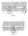
- Fig. 3 is an assembled sectional view of a portion of the heater taken along line 3-3 of Fig. 6;
- Fig. 4 is a side sectional view taken along the line 4-4 of Fig. 3;
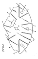
- Fig. 5 is a top view of a flexible, crush plate that is employed with the heater assembly; and
- Fig. 6 is a view taken along the line 6-6 of Fig. 1 or 2.
- Reference is now made to Fig. 1 of the drawing wherein there is schematically illustrated, in cross-section, a diffusion pump including an electric heater assembly 10 in accordance with the invention. The diffusion pump includes a cylindrical
exterior wall 11 that is wrapped by aspiral cooling coil 12. Secured to the bottom ofcylinder 11 is a relatively massivemetal boiler plate 13, having anupper face 14 that forms a floor forpool 15 of vaporizable diffusion pump fluid or oil.Lower face 16 ofplate 13 contacts a first surface of a coil-like tubular electric heater orheating element 17, having a second side that contacts thin, flexiblemetal crush plate 18, which in turn abuts against a second relativelymassive metal plate 19.Nuts 20, threaded onto threadedstuds 21, that extend fromface 16 ofplate 13, andwashers 41urge plate 19 againstplate 18, which in turn contacts tubularelectric heater 17 to urge the heater againstface 16. Thus,plates electric heater 17, form heater assembly 10 that heats the liquid inpool 15 to a sufficiently high temperature to cause the liquid to boil. - Vapor from
pool 15 flows to a series of concentric diffusion pump nozzles 25-27 and to anejector nozzle 28. The vapor flowing from nozzles 25-27 traps molecules from a high vacuum load connected toflange 24 and is condensed on the interior surface ofcylinder 11.. The condensed vapor oncylinder 11 flows, by gravity, back topool 15 along the walls of the cylinder, in a manner well-known to those skilled in the art. In line withejector nozzle 28 is a tapered, horizontally extendingtube 29, also wrapped with acooling coil 30. In fluid flow relationship withtube 29 isforeline 31, connected to a foreline pump in a manner well-known to those skilled in the art. - Referring to Figs. 2-6, tubular
electric heater 17 of heater assembly 10 includes a tubular, generallycircular cross-section sheath 33, preferably having flat upper and lower faces.Sheath 33 is made of a suitable, relatively temperature stable metal, such as the alloy Inconel, and is formed as a flat convoluted sector having a relatively long total length. Withinsheath 33 is aresistive heater coil 34, preferably fabricated of Nichrome. In the space betweencoil 34 and the interior surface ofsheath 33 is an electrically insulating material having high thermal conductivity, such asmagnesium oxide powder 35. Electric heaters having these properties are generally commercially available. However, the commercially available heaters do not have consistent geometries because the distance between opposite sides thereof is subject to about ±0.0375 cm variations. Hence, maintaining contact between the top side of tubularelectric heater 17 and the bottom face ofboiler plate 13 presents a problem, which is solved in accordance with the invention by utilizingcrush plate 18 which urges the top side ofsheath 33 against the bottom face of the boiler plate. - Typically, tubular
electric heater 17 is energized by a three-phase, 240 volt source that supplies 3100 watts to the coil. If tubularelectric heater 17 is not loaded sufficiently along its length so that substantial portions of its length are not contacted by a relatively high thermal load, the heater has a tendency to develop hot spots, i.e., the exterior surface ofsheath 33 attains a temperature of about 750°C or higher. If the exterior surface ofsheath 33 attains such a high temperature, the life ofcoil 34 is shortened and heater assembly 10 or a significant segment thereof must be replaced. -
Crush plate 18 is actually an assemblage of three plates 18.1, 18.2 and 18.3, each formed as a sector having an angular extent of 120°, as illustrated in Figs. 5 and 6. Each of plate segments 18.1, 18.2 and 18.3 is formed of a temperature stable, flexible metal sheet of a suitable material, such as stainless steel or Inconel. In a typical embodiment, the desired flexibility is attained by formingsheet 18 with stock having a thickness of approximately 0.045 cm. Each plate segment includes a number of elongated segments ordimples 37, typically having a width of approximately 0.3 cm and a length of about 7.5 cm.Dimples 37 extend approximately .225 cm from the face ofplate 18 that isproximate heater 17 and have sufficient length to engage a plurality of different segments of the heater so that each 7.5 cm length or less ofsheath 33 touches adimple 37. The spacing ofdimples 37 is sufficient to force almost the entire length of the top side ofsheath 33 against the bottom face ofplate 13 to prevent hot spots from developing along the surface ofsheath 33. In one embodiment, dimples 37 are spaced from each other so that there is contact between adjacent dimples and the exterior ofsheath 33 for at least every 7.5 cm of the length ofheater 17. In practice, this has been found to be adequate. The number of dimples could be increased if dimensional irregularities justify it. - Each of
dimples 37 projects upwardly from the remainder ofplate 18 to assure that there is substantial contact between the upper surface of the dimple and the lower side ofsheath 33, for variations of the sheath diameter within its tolerance. Hence, for certain portions ofsheath 33, as illustrated on the right side of Figs. 3 and 4,dimple 37 is substantially depressed by the exterior ofsheath 33, while other portions ofsheath 33, as illustrated on the left side of Fig. 3 or 4, only slightly depress the dimple it contacts. In all instances, there is sufficient contact area betweensheath 33 and the upper portion ofdimples 37 to assure adequate thermal loading and heat transfer betweenheater 17 andplate 13. -
Plates circular apertures studs 21 extend.Heater 17 is similarly arranged so thatstuds 21 extend between spaces of adjacent turns thereof. Heater 10 is assembled by placingheater 17 so that it abuts againstlower face 16 ofplate 13.Plate 18 is then placed against the side ofsheath 33 that is opposite from the side of the sheath that abuts againstboiler plate face 16.Plate 19 is thereafter placed against the face ofplate 18 opposite from the face of that plate which abuts against one side ofsheath 33. Thereafter,washers 41 are placed overstuds 21 andnuts 20 are threaded onto the studs. The washers are threaded onto the studs until they urgeplate 19 againstplate 18, the dimples of which are crushed against one side ofsheath 33, the other side of which abuts againstface 16. All ofdimples 37 are at least partially crushed at each contact point withsheath 33, regardless of variations in the geometry (diameter or shape) of the sheath or variations in the flatness ofplate 19. - To provide three-phase electrical energization for
heater 17, the heater includes six threaded nickel rods 42.1―42.6, generally indicated byreference numeral 42, that extend from the end ofsheath 33. The vertical ends ofsheath 33 extend through alignedslots plates heater 17 are connected in a delta configuration, but it is to be understood that a Y connection can be employed if desired. - While there has been described and illustrated one specific embodiment of the invention, it will be clear that variations in the details of the embodiment specifically illustrated and described may be made without departing from the true spirit and scope of the invention as defined in the appended claims. For example, the elongated dimples can be replaced by numerous, judiciously placed teats to provide the desired loading.
Claims (10)
Applications Claiming Priority (2)
| Application Number | Priority Date | Filing Date | Title |
|---|---|---|---|
| US05/898,567 US4251713A (en) | 1978-04-21 | 1978-04-21 | Electric heater assembly for diffusion pumps |
| US898567 | 1997-07-21 |
Publications (3)
| Publication Number | Publication Date |
|---|---|
| EP0015976A4 EP0015976A4 (en) | 1980-07-08 |
| EP0015976A1 EP0015976A1 (en) | 1980-10-01 |
| EP0015976B1 true EP0015976B1 (en) | 1982-08-11 |
Family
ID=25409642
Family Applications (1)
| Application Number | Title | Priority Date | Filing Date |
|---|---|---|---|
| EP79900465A Expired EP0015976B1 (en) | 1978-04-21 | 1979-11-19 | Electric heater assembly for diffusion pumps |
Country Status (6)
| Country | Link |
|---|---|
| US (1) | US4251713A (en) |
| EP (1) | EP0015976B1 (en) |
| JP (1) | JPS55500282A (en) |
| DE (1) | DE2963524D1 (en) |
| IT (1) | IT1112525B (en) |
| WO (1) | WO1979000957A1 (en) |
Families Citing this family (6)
| Publication number | Priority date | Publication date | Assignee | Title |
|---|---|---|---|---|
| JPS62500430A (en) * | 1984-09-24 | 1987-02-26 | ニロ プラン アクチエンゲゼルシヤフト | A frying pan having an electric planar heating element, a pan body, a tank part, and a tank bottom. |
| DE3437347A1 (en) * | 1984-10-11 | 1986-04-24 | E.G.O. Elektro-Geräte Blanc u. Fischer, 7519 Oberderdingen | TUBE BODY HEATING UNIT |
| US4649263A (en) * | 1985-12-16 | 1987-03-10 | Goodlaxson Mfg. Inc. | Heating kettle |
| FR2599477B1 (en) * | 1986-05-30 | 1989-01-06 | Perrichon | HIGH-EFFICIENCY ELECTRIC COOKING DEVICE MORE SPECIFICALLY FOR RESTAURANTS OR COLLECTIVES |
| SU1742526A1 (en) * | 1990-03-14 | 1992-06-23 | Научно-производственное объединение "Вакууммашприбор" | Vapor-jet vacuum pump |
| DE102004053006A1 (en) * | 2004-10-29 | 2006-05-04 | Tu Hamburg-Harburg | Propellant pump in microsystem technology |
Family Cites Families (16)
| Publication number | Priority date | Publication date | Assignee | Title |
|---|---|---|---|---|
| US2899126A (en) * | 1959-08-11 | Sadler | ||
| DE230591C (en) * | ||||
| DE630276C (en) * | 1936-05-25 | Hans Lipke | Device for pressing a flexible electrical heating element, which rests directly on the parts of a device to be heated | |
| US1573787A (en) * | 1925-05-25 | 1926-02-16 | Edison Electric Appliance Co | Electric heater |
| US1743301A (en) * | 1926-10-29 | 1930-01-14 | Beardsley & Wolcott Mfg Co | Electrical heating device |
| DK49807C (en) * | 1933-07-28 | 1935-01-28 | Forenede Jernstoeberier Akties | Device for electric hot plates, irons and similar appliances. |
| GB450882A (en) * | 1935-02-16 | 1936-07-27 | Neville Wallace Gilbert | Improvements in or relating to electrically-heated hot-plates and utensils |
| GB611374A (en) * | 1946-04-30 | 1948-10-28 | John Pursall Moulson | Improvements relating to means for clamping heating elements in electrically-heated apparatus |
| US2522718A (en) * | 1947-03-13 | 1950-09-19 | Knapp Monarch Co | Vaporizer |
| DE874622C (en) * | 1950-10-14 | 1953-04-27 | Landruf G M B H | Electric boiler |
| US2772344A (en) * | 1954-01-25 | 1956-11-27 | Handling Equipment & Mfg Compa | Electric water heater |
| US3227361A (en) * | 1963-04-19 | 1966-01-04 | Cons Vacuum Corp | Heater for vacuum pump |
| US3258196A (en) * | 1963-11-04 | 1966-06-28 | Mount Vernon Res Company | Ultrahigh vacuum pump |
| FR1382330A (en) * | 1963-11-08 | 1964-12-18 | Cie Ind Francaise Tubes Elect | Improvement in oil vapor diffusion pumps |
| US3317709A (en) * | 1964-05-11 | 1967-05-02 | Mc Graw Edison Co | Electric griddle |
| GB1285042A (en) * | 1969-01-15 | 1972-08-09 | Power Frequency Heating Ltd | Improvements in or relating to heater assemblies |
-
1978
- 1978-04-21 US US05/898,567 patent/US4251713A/en not_active Expired - Lifetime
-
1979
- 1979-04-09 WO PCT/US1979/000218 patent/WO1979000957A1/en not_active Ceased
- 1979-04-09 DE DE7979900465T patent/DE2963524D1/en not_active Expired
- 1979-04-09 JP JP50073779A patent/JPS55500282A/ja active Pending
- 1979-04-23 IT IT22078/79A patent/IT1112525B/en active
- 1979-11-19 EP EP79900465A patent/EP0015976B1/en not_active Expired
Also Published As
| Publication number | Publication date |
|---|---|
| JPS55500282A (en) | 1980-05-08 |
| US4251713A (en) | 1981-02-17 |
| EP0015976A4 (en) | 1980-07-08 |
| IT1112525B (en) | 1986-01-20 |
| EP0015976A1 (en) | 1980-10-01 |
| DE2963524D1 (en) | 1982-10-07 |
| IT7922078A0 (en) | 1979-04-23 |
| WO1979000957A1 (en) | 1979-11-15 |
Similar Documents
| Publication | Publication Date | Title |
|---|---|---|
| US2875312A (en) | Heating assembly and method of production thereof | |
| US4394564A (en) | Solid plate heating unit | |
| JP2813148B2 (en) | Ceramic products | |
| US4876436A (en) | PTC air heater employing triangular PTC heating elements | |
| US4972067A (en) | PTC heater assembly and a method of manufacturing the heater assembly | |
| US4251713A (en) | Electric heater assembly for diffusion pumps | |
| US4125761A (en) | Bilateral heater unit | |
| KR102224630B1 (en) | Heating device | |
| US3920963A (en) | Resistance heater with improved thermocouple | |
| KR910000858Y1 (en) | Infrared heater | |
| US4680449A (en) | Heater for heating heat shrinkable tube | |
| US6414281B1 (en) | Hot-toe multicell electric heater | |
| JPH1069975A (en) | Induction heating cooker | |
| US2101110A (en) | Heating unit | |
| US2310325A (en) | Electrical heating unit | |
| US20080083733A1 (en) | Radiant heater | |
| US4870256A (en) | Graphite holding elements for heating bars in industrial furnaces | |
| JPS6341753Y2 (en) | ||
| US3400356A (en) | Screen heater with an outer metallic sheath | |
| GB1581127A (en) | Electrical heating devices | |
| NL8004400A (en) | HEATING ELEMENT FOR AN ELECTRIC OVEN. | |
| US4687911A (en) | Electric furnace heater | |
| CN223899342U (en) | PTC heater with heat pipe | |
| JP3935696B2 (en) | Cartridge heater | |
| GB1561913A (en) | Electrical resistance heating element with heat tgransferring characteristics |
Legal Events
| Date | Code | Title | Description |
|---|---|---|---|
| PUAI | Public reference made under article 153(3) epc to a published international application that has entered the european phase |
Free format text: ORIGINAL CODE: 0009012 |
|
| 17P | Request for examination filed | ||
| AK | Designated contracting states |
Designated state(s): CH DE FR GB |
|
| GRAA | (expected) grant |
Free format text: ORIGINAL CODE: 0009210 |
|
| AK | Designated contracting states |
Designated state(s): CH DE FR GB |
|
| REF | Corresponds to: |
Ref document number: 2963524 Country of ref document: DE Date of ref document: 19821007 |
|
| PGFP | Annual fee paid to national office [announced via postgrant information from national office to epo] |
Ref country code: FR Payment date: 19830401 Year of fee payment: 5 |
|
| PGFP | Annual fee paid to national office [announced via postgrant information from national office to epo] |
Ref country code: CH Payment date: 19830427 Year of fee payment: 5 |
|
| PGFP | Annual fee paid to national office [announced via postgrant information from national office to epo] |
Ref country code: DE Payment date: 19830507 Year of fee payment: 5 |
|
| PG25 | Lapsed in a contracting state [announced via postgrant information from national office to epo] |
Ref country code: CH Effective date: 19840430 |
|
| PG25 | Lapsed in a contracting state [announced via postgrant information from national office to epo] |
Ref country code: FR Free format text: LAPSE BECAUSE OF NON-PAYMENT OF DUE FEES Effective date: 19841228 |
|
| REG | Reference to a national code |
Ref country code: CH Ref legal event code: PL |
|
| PG25 | Lapsed in a contracting state [announced via postgrant information from national office to epo] |
Ref country code: DE Effective date: 19850101 |
|
| REG | Reference to a national code |
Ref country code: FR Ref legal event code: ST |
|
| PG25 | Lapsed in a contracting state [announced via postgrant information from national office to epo] |
Ref country code: GB Effective date: 19890409 |
|
| GBPC | Gb: european patent ceased through non-payment of renewal fee | ||
| PLBE | No opposition filed within time limit |
Free format text: ORIGINAL CODE: 0009261 |
|
| STAA | Information on the status of an ep patent application or granted ep patent |
Free format text: STATUS: NO OPPOSITION FILED WITHIN TIME LIMIT |