EP0015692B1 - A process for producing a magnetic recording medium - Google Patents
A process for producing a magnetic recording medium Download PDFInfo
- Publication number
- EP0015692B1 EP0015692B1 EP80300524A EP80300524A EP0015692B1 EP 0015692 B1 EP0015692 B1 EP 0015692B1 EP 80300524 A EP80300524 A EP 80300524A EP 80300524 A EP80300524 A EP 80300524A EP 0015692 B1 EP0015692 B1 EP 0015692B1
- Authority
- EP
- European Patent Office
- Prior art keywords
- cluster
- substrate
- magnetic
- chromium
- magnetic recording
- Prior art date
- Legal status (The legal status is an assumption and is not a legal conclusion. Google has not performed a legal analysis and makes no representation as to the accuracy of the status listed.)
- Expired
Links
Images
Classifications
-
- G—PHYSICS
- G11—INFORMATION STORAGE
- G11B—INFORMATION STORAGE BASED ON RELATIVE MOVEMENT BETWEEN RECORD CARRIER AND TRANSDUCER
- G11B5/00—Recording by magnetisation or demagnetisation of a record carrier; Reproducing by magnetic means; Record carriers therefor
- G11B5/62—Record carriers characterised by the selection of the material
- G11B5/64—Record carriers characterised by the selection of the material comprising only the magnetic material without bonding agent
- G11B5/65—Record carriers characterised by the selection of the material comprising only the magnetic material without bonding agent characterised by its composition
- G11B5/658—Record carriers characterised by the selection of the material comprising only the magnetic material without bonding agent characterised by its composition containing oxygen, e.g. molecular oxygen or magnetic oxide
-
- C—CHEMISTRY; METALLURGY
- C23—COATING METALLIC MATERIAL; COATING MATERIAL WITH METALLIC MATERIAL; CHEMICAL SURFACE TREATMENT; DIFFUSION TREATMENT OF METALLIC MATERIAL; COATING BY VACUUM EVAPORATION, BY SPUTTERING, BY ION IMPLANTATION OR BY CHEMICAL VAPOUR DEPOSITION, IN GENERAL; INHIBITING CORROSION OF METALLIC MATERIAL OR INCRUSTATION IN GENERAL
- C23C—COATING METALLIC MATERIAL; COATING MATERIAL WITH METALLIC MATERIAL; SURFACE TREATMENT OF METALLIC MATERIAL BY DIFFUSION INTO THE SURFACE, BY CHEMICAL CONVERSION OR SUBSTITUTION; COATING BY VACUUM EVAPORATION, BY SPUTTERING, BY ION IMPLANTATION OR BY CHEMICAL VAPOUR DEPOSITION, IN GENERAL
- C23C14/00—Coating by vacuum evaporation, by sputtering or by ion implantation of the coating forming material
- C23C14/0021—Reactive sputtering or evaporation
-
- G—PHYSICS
- G11—INFORMATION STORAGE
- G11B—INFORMATION STORAGE BASED ON RELATIVE MOVEMENT BETWEEN RECORD CARRIER AND TRANSDUCER
- G11B5/00—Recording by magnetisation or demagnetisation of a record carrier; Reproducing by magnetic means; Record carriers therefor
- G11B5/84—Processes or apparatus specially adapted for manufacturing record carriers
- G11B5/851—Coating a support with a magnetic layer by sputtering
-
- H—ELECTRICITY
- H01—ELECTRIC ELEMENTS
- H01F—MAGNETS; INDUCTANCES; TRANSFORMERS; SELECTION OF MATERIALS FOR THEIR MAGNETIC PROPERTIES
- H01F10/00—Thin magnetic films, e.g. of one-domain structure
- H01F10/08—Thin magnetic films, e.g. of one-domain structure characterised by magnetic layers
- H01F10/10—Thin magnetic films, e.g. of one-domain structure characterised by magnetic layers characterised by the composition
- H01F10/18—Thin magnetic films, e.g. of one-domain structure characterised by magnetic layers characterised by the composition being compounds
-
- H—ELECTRICITY
- H01—ELECTRIC ELEMENTS
- H01F—MAGNETS; INDUCTANCES; TRANSFORMERS; SELECTION OF MATERIALS FOR THEIR MAGNETIC PROPERTIES
- H01F41/00—Apparatus or processes specially adapted for manufacturing or assembling magnets, inductances or transformers; Apparatus or processes specially adapted for manufacturing materials characterised by their magnetic properties
- H01F41/14—Apparatus or processes specially adapted for manufacturing or assembling magnets, inductances or transformers; Apparatus or processes specially adapted for manufacturing materials characterised by their magnetic properties for applying magnetic films to substrates
-
- Y—GENERAL TAGGING OF NEW TECHNOLOGICAL DEVELOPMENTS; GENERAL TAGGING OF CROSS-SECTIONAL TECHNOLOGIES SPANNING OVER SEVERAL SECTIONS OF THE IPC; TECHNICAL SUBJECTS COVERED BY FORMER USPC CROSS-REFERENCE ART COLLECTIONS [XRACs] AND DIGESTS
- Y10—TECHNICAL SUBJECTS COVERED BY FORMER USPC
- Y10S—TECHNICAL SUBJECTS COVERED BY FORMER USPC CROSS-REFERENCE ART COLLECTIONS [XRACs] AND DIGESTS
- Y10S428/00—Stock material or miscellaneous articles
- Y10S428/90—Magnetic feature
-
- Y—GENERAL TAGGING OF NEW TECHNOLOGICAL DEVELOPMENTS; GENERAL TAGGING OF CROSS-SECTIONAL TECHNOLOGIES SPANNING OVER SEVERAL SECTIONS OF THE IPC; TECHNICAL SUBJECTS COVERED BY FORMER USPC CROSS-REFERENCE ART COLLECTIONS [XRACs] AND DIGESTS
- Y10—TECHNICAL SUBJECTS COVERED BY FORMER USPC
- Y10T—TECHNICAL SUBJECTS COVERED BY FORMER US CLASSIFICATION
- Y10T428/00—Stock material or miscellaneous articles
- Y10T428/26—Web or sheet containing structurally defined element or component, the element or component having a specified physical dimension
- Y10T428/263—Coating layer not in excess of 5 mils thick or equivalent
- Y10T428/264—Up to 3 mils
- Y10T428/265—1 mil or less
-
- Y—GENERAL TAGGING OF NEW TECHNOLOGICAL DEVELOPMENTS; GENERAL TAGGING OF CROSS-SECTIONAL TECHNOLOGIES SPANNING OVER SEVERAL SECTIONS OF THE IPC; TECHNICAL SUBJECTS COVERED BY FORMER USPC CROSS-REFERENCE ART COLLECTIONS [XRACs] AND DIGESTS
- Y10—TECHNICAL SUBJECTS COVERED BY FORMER USPC
- Y10T—TECHNICAL SUBJECTS COVERED BY FORMER US CLASSIFICATION
- Y10T428/00—Stock material or miscellaneous articles
- Y10T428/31504—Composite [nonstructural laminate]
- Y10T428/31678—Of metal
Definitions
- This invention relates to the production of magnetic recording media such as magnetic tapes, magnetic discs and magnetic drums.
- These magnetic recording media have conventionally been produced by dispersing a powdery magnetic material such as gamma-iron oxide and chromium oxide in a resin binder, and coating the resulting dispersion on a substrate such as a polyethylene tetephthatate or aluminium substrate.
- a powdery magnetic material such as gamma-iron oxide and chromium oxide
- a substrate such as a polyethylene tetephthatate or aluminium substrate.
- DE-A-2622597 describes the manufacture of a magnetic recording medium by ionised cluster beam deposition on a substrate of a ferromagnetic material containing at least one of iron, cobalt and nickel.
- lonised cluster beam deposition is known from GB-A-1493088.
- a material such as chromium is heated in a closed type crucible having an injection nozzle.
- a vapor is jetted out from the nozzle to generate a cluster of molecules.
- Electron beams generated by an electron beam generator provided in the same vacuum chamber as the crucible are impinged against the cluster thereby to ionise the cluster.
- the cluster ions are accelerated in an electric field and deposited on the substrate.
- the present invention provides a process for producing a magnetic recording medium by depositing a ferromagnetic material on a substrate composed of a non-magnetic material by ionized cluster beam deposition, characterised by heating a closed type crucible having an injection nozzle and containing metallic chromium or chromium oxide and simultaneously supplying oxygen to the vicinity of the injection nozzle in a vacuum chamber kept at 10- 3 to 10- 8 torr (0.13 to 1.3 x 10- Pa) thereby to generate a cluster of chromium dioxide molecules, impinging electron beams generated by an electron beam generator provided within the same vacuum chamber against the cluster thereby to ionize the cluster, accelerating the generated cluster ions in an electric field, and depositing the ions on the substrate.
- the magnetic recording medium produced in accordance with the invention has high abrasion resistance and superior magnetic properties such as coercive force, residual magnetic flux density and squareness ratio and has a ferromagnetic layer of high packing density firmly adherent to the substrate.
- a thin ferro-magnetic film having good crystallinity is obtained because it is formed by a migration effect in which the cluster ions impinging against the surface of the substrate separate into individual atomic particles by the energy of impingement and migrate on the surface of the substrate, a self heating effect on the surface of the thin film in which a part of the energy generated upon the impingement against the surface of the substrate is converted to a heat energy to cause a localized temperature rise and a chemically activating effect by the presence of ions.
- this method does not require heating the substrate owing to the aforesaid effects, it can be applied conveniently to the production of magnetic recording media comprising as a substrate polymeric material having a low softening temperature such as polyethylene terephthalate.
- the magnetic layer deposited on the surface of the substrate by the ionized cluster beam depositing method is of high packing density, firmly adheres to the substrate, and has a smooth surface. Hence, this layer exhibits superior magnetic properties.
- the substrate used in this invention is composed of a non-magnetic material.
- the shape of the substrate may be determined depending upon the manner in which the resulting magnetic recording medium is to be used, and includes, for example, tapes, films, disks and drums.
- the non-magnetic material as the substrate are polymeric materials such as polyethylene terephthalate, polybutylene terephthalate, polyethylene, polypropylene, polyvinyl chloride, polyvinyl fluoride, cellulose acetate, cellulose butyl acetate, polycarbonate, polyimides, polyether sulfone and polyparabanic acid; ceramic materials such as glass, porcelain and ceramics; and non-magnetic metal materials such as aluminum, copper and a copper-zinc alloy.
- the thickness of the deposited layer is not limited in particular. Usually, it is 0.01 to 10 micrometers, preferably 0.05 to 10 micrometers, more preferably 0.1 to 1 micrometer.
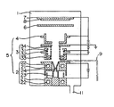
- the reference numeral 1 represents a vacuum chamber having an exhaust port 11 to which a vacuum pump is connected.
- the vacuum chamber 1 includes a cluster ionizing gun unit 5 consisting of a cluster generator 2, an ionizing device 3 and a cluster ion accelerating electrode 4; a shutter 6; and a substrate holder 7.
- the cluster generator 2 is made up of an electrode 21 having a cooling mechanism 22 and a closed type crucible 23 having an injection nozzle 24 of a small diameter.
- the ionizing device 3 consists of filaments 31 for releasing hot electrons, a mesh electrode 34 for accelerating the release electrons in an electric field, and a guard 32 for controlling the electric field which has a cooling means 33.
- a substrate 8 is set in the substrate holder 7, and metallic chromium or chromium oxide (CrO, Cr z 0 3 , CrO z' Cr z O s Cr0 3 etc) are fed into the crucible 23.
- the vacuum chamber is evacuated through the exhaust port 11 to maintain a high vacuum of 10- 3 to 10- 8 torr (0.13 to 1.3 x 10- 6 Pa) therein.
- an electric current is passed through the electrode 21 to heat the closed type crucible 23.
- the ferromagnetic material supplied to the crucible 23 is heated so that its vapor pressure reaches 10- 2 torr (1.3 Pa) to several torr (several hundred Pa).
- the early stage of the ionized cluster beam deposition be carried out at a high voltage of -4 KV to -15 KV, and after the thin layer has been formed on the substrate by the cluster ions, the deposition bee carried out at a low voltage of -0.1 KV to -4 KV.
- the cluster ion accelerating electrode 4 is connected by a wire to the substrate holder 7 so that they have the same potential.
- the metallic chromium and chromium oxides have as high a purity as possible.
- Metallic chromium of high purity is most preferred.
- the oxygen is also desirably of high purity. The amount of oxygen is prescribed so that the pressure in the vacuum chamber 1 does not exceed 10- 3 torr (0.13 Pa).
- chromium dioxide is deposited on the substrate by ionized cluster beam deposition in the process of this invention, no significant amount of electric charge builds up even on the surface of an insulating substrate, and a rise in the temperature of the substrate is small. Accordingly, in the process of this invention, low-melting materials or electrical insulating materials can also be used conveniently as the substrate. Furthermore, since the cluster ion beam deposition is carried out in a high vacuum, and the kinetic energy of the cluster ions is uniform and large, the chromium dioxide is deposited on the surface of the substrate without involving other substances. The deposited layer has a smooth surface and a high packing density, and firmly adheres to the substrate.
- the magnetic recording medium produced by the process of this invention has superior magnetic properties such as coercive force, residual magnetic flux density and squareness ratio, and the ferromagnetic layer has high mechanical strength.
- the ferromagnetic layer does not easily undergo peeling, wear or damage even when it is scanned in contact with a magnetic head.
- the surface of the ferromagnetic layer is smooth, the wear of the magnetic head is also small.
- the magnetic recording media of this invention are useful as magnetic tapes such as open reel tapes, cassette tapes and video tapes, and in the field of digital recording as magnetic disks, magnetic cards, magnetic tickets, magnetic season tickets, magnetic notebooks and magnetic drums.
- the thickness of the deposited layer composed mainly of chromium dioxide in the resulting magnetic recording medium was about 500 A.
- the deposited layer was analyzed by an X-ray photoelectron spectroscopy, and it was ascertained that chromium dioxide was deposited.
- the structure of the magnetic domain of the magnetic recording medium was observed by a polarizing microscope, and a fine maze domain was noted.
- Example 2 Using the same apparatus as in Example 1, 20 g of chromium metal lumps (purity 99.99%) were fed into the closed type crucible, and deposited on a polyethylene terephthalate film having a thickness of 50 microns by the ionized cluster beam deposition method under the conditions shown in Table 2.
- the thickness of the deposited layer was about 1400 A.
- the magnetic properties of the resulting magnetic recording medium were measured by a dc magnetization measuring device. It was found to have a saturation magnetic flux density of 3700 gauss, a residual magnetic flux density of 3200 gauss and a coercive force of 550 oersteds.
Landscapes
- Engineering & Computer Science (AREA)
- Chemical & Material Sciences (AREA)
- Power Engineering (AREA)
- Mechanical Engineering (AREA)
- Chemical Kinetics & Catalysis (AREA)
- Materials Engineering (AREA)
- Manufacturing & Machinery (AREA)
- Metallurgy (AREA)
- Organic Chemistry (AREA)
- Physics & Mathematics (AREA)
- Spectroscopy & Molecular Physics (AREA)
- Manufacturing Of Magnetic Record Carriers (AREA)
- Physical Vapour Deposition (AREA)
Description
- This invention relates to the production of magnetic recording media such as magnetic tapes, magnetic discs and magnetic drums.
- These magnetic recording media have conventionally been produced by dispersing a powdery magnetic material such as gamma-iron oxide and chromium oxide in a resin binder, and coating the resulting dispersion on a substrate such as a polyethylene tetephthatate or aluminium substrate. With such magnetic recording media, however, high density recording is impossible because there is a limit to the minimum particle diameter of the powdery magnetic material which can be attained and the thickness of the recording layer cannot be reduced.
- In an attempt to obtain magnetic recording media capable of achieving high-density recording, methods were developed which involve depositing a ferromagnetic material on a substrate such as polyethylene terephthalate by vacuum deposition, ion-sputtering or ion-plating. A magnetic layer formed by vacuum deposition undergoes peeling, wear or damage upon friction and cannot be repeatedly used, because the magnetic particles are deposited at a low density and the bond strength between the magnetic layer and the substrate is low. Since ion-plating or sputtering is carried out under a low vacuum of from 10-1 to 10-3 torr (13 to 0.13 Pa), a magnetic layer so deposited unavoidably contains impurities, and therefore has poor crystallinity and a low squareness ratio.
- DE-A-2622597 describes the manufacture of a magnetic recording medium by ionised cluster beam deposition on a substrate of a ferromagnetic material containing at least one of iron, cobalt and nickel.
- lonised cluster beam deposition is known from GB-A-1493088. A material such as chromium is heated in a closed type crucible having an injection nozzle. A vapor is jetted out from the nozzle to generate a cluster of molecules. Electron beams generated by an electron beam generator provided in the same vacuum chamber as the crucible are impinged against the cluster thereby to ionise the cluster. The cluster ions are accelerated in an electric field and deposited on the substrate.
- The present invention provides a process for producing a magnetic recording medium by depositing a ferromagnetic material on a substrate composed of a non-magnetic material by ionized cluster beam deposition, characterised by heating a closed type crucible having an injection nozzle and containing metallic chromium or chromium oxide and simultaneously supplying oxygen to the vicinity of the injection nozzle in a vacuum chamber kept at 10-3 to 10-8 torr (0.13 to 1.3 x 10- Pa) thereby to generate a cluster of chromium dioxide molecules, impinging electron beams generated by an electron beam generator provided within the same vacuum chamber against the cluster thereby to ionize the cluster, accelerating the generated cluster ions in an electric field, and depositing the ions on the substrate.
- The magnetic recording medium produced in accordance with the invention has high abrasion resistance and superior magnetic properties such as coercive force, residual magnetic flux density and squareness ratio and has a ferromagnetic layer of high packing density firmly adherent to the substrate.
- According to the cluster ion beam depositing method, a thin ferro-magnetic film having good crystallinity is obtained because it is formed by a migration effect in which the cluster ions impinging against the surface of the substrate separate into individual atomic particles by the energy of impingement and migrate on the surface of the substrate, a self heating effect on the surface of the thin film in which a part of the energy generated upon the impingement against the surface of the substrate is converted to a heat energy to cause a localized temperature rise and a chemically activating effect by the presence of ions. Moreover, since this method does not require heating the substrate owing to the aforesaid effects, it can be applied conveniently to the production of magnetic recording media comprising as a substrate polymeric material having a low softening temperature such as polyethylene terephthalate.
- The magnetic layer deposited on the surface of the substrate by the ionized cluster beam depositing method is of high packing density, firmly adheres to the substrate, and has a smooth surface. Hence, this layer exhibits superior magnetic properties.
- The substrate used in this invention is composed of a non-magnetic material. The shape of the substrate may be determined depending upon the manner in which the resulting magnetic recording medium is to be used, and includes, for example, tapes, films, disks and drums. Examples of the non-magnetic material as the substrate are polymeric materials such as polyethylene terephthalate, polybutylene terephthalate, polyethylene, polypropylene, polyvinyl chloride, polyvinyl fluoride, cellulose acetate, cellulose butyl acetate, polycarbonate, polyimides, polyether sulfone and polyparabanic acid; ceramic materials such as glass, porcelain and ceramics; and non-magnetic metal materials such as aluminum, copper and a copper-zinc alloy.
- The thickness of the deposited layer is not limited in particular. Usually, it is 0.01 to 10 micrometers, preferably 0.05 to 10 micrometers, more preferably 0.1 to 1 micrometer.
- The present invention is described below more specifically with reference to the, accompanying drawing which is a diagrammatic view showing an example of an ionized cluster beam deposition apparatus used in this invention.
- Referring to the drawing, the reference numeral 1 represents a vacuum chamber having an exhaust port 11 to which a vacuum pump is connected. The vacuum chamber 1 includes a cluster ionizing
gun unit 5 consisting of acluster generator 2, anionizing device 3 and a clusterion accelerating electrode 4; ashutter 6; and asubstrate holder 7. Thecluster generator 2 is made up of anelectrode 21 having a cooling mechanism 22 and a closedtype crucible 23 having aninjection nozzle 24 of a small diameter. The ionizingdevice 3 consists of filaments 31 for releasing hot electrons, a mesh electrode 34 for accelerating the release electrons in an electric field, and a guard 32 for controlling the electric field which has a cooling means 33. - In the production of a magnetic recording medium a
substrate 8 is set in thesubstrate holder 7, and metallic chromium or chromium oxide (CrO, Crz03, CrOz' CrzOs Cr03 etc) are fed into thecrucible 23. The vacuum chamber is evacuated through the exhaust port 11 to maintain a high vacuum of 10-3 to 10-8 torr (0.13 to 1.3 x 10⁻⁶ Pa) therein. Then, an electric current is passed through theelectrode 21 to heat the closedtype crucible 23. Thus, the ferromagnetic material supplied to thecrucible 23 is heated so that its vapor pressure reaches 10-2 torr (1.3 Pa) to several torr (several hundred Pa). The ratio of the "pressure in the vacuum chamber" to the "pressure in thecrucible 23" is prescribed at less than 1/100, whereupon a vapor of metallic chromium or chromium oxide is jetted out from theinjection nozzle 24 into an oxygen atmosphere supplied from an oxygen supplying device 9 to form a cluster composed of chromium dioxide molecules. In the ionizingdevice 3, the filaments 31 are heated by the passing of electric current to release electrons. The released electrons are accelerated by the earthed mesh electrode 34 and the filaments 31 to which a direct-current voltage of -1 OOV to 1000V has been applied. The accelerated electrons collide with the cluster to ionize it and thus form cluster ions. The cluster ions are accelerated in the direction of thesubstrate 8 by the clusterion accelerating electrode 4 to which a direct-current voltage of -0.1 KV to -15 KV has been applied. Normally, the cluster ions are shielded by the shutter. When the generation of cluster ions becomes uniform, theshutter 6 is removed to allow the cluster ions to collide with thesubstrate 8. As a result, a uniform deposited film of chromium dioxide is formed on the substrate. Since the adhesion between the chromium dioxide layer deposited by cluster ions and the substrate becomes better at higher voltages of the cluster ion accelerating electrode, it is preferred that the early stage of the ionized cluster beam deposition be carried out at a high voltage of -4 KV to -15 KV, and after the thin layer has been formed on the substrate by the cluster ions, the deposition bee carried out at a low voltage of -0.1 KV to -4 KV. Preferably, the clusterion accelerating electrode 4 is connected by a wire to thesubstrate holder 7 so that they have the same potential. - Preferably, the metallic chromium and chromium oxides have as high a purity as possible. Metallic chromium of high purity is most preferred. The oxygen is also desirably of high purity. The amount of oxygen is prescribed so that the pressure in the vacuum chamber 1 does not exceed 10-3 torr (0.13 Pa).
- Since chromium dioxide is deposited on the substrate by ionized cluster beam deposition in the process of this invention, no significant amount of electric charge builds up even on the surface of an insulating substrate, and a rise in the temperature of the substrate is small. Accordingly, in the process of this invention, low-melting materials or electrical insulating materials can also be used conveniently as the substrate. Furthermore, since the cluster ion beam deposition is carried out in a high vacuum, and the kinetic energy of the cluster ions is uniform and large, the chromium dioxide is deposited on the surface of the substrate without involving other substances. The deposited layer has a smooth surface and a high packing density, and firmly adheres to the substrate. Accordingly, the magnetic recording medium produced by the process of this invention has superior magnetic properties such as coercive force, residual magnetic flux density and squareness ratio, and the ferromagnetic layer has high mechanical strength. Hence, the ferromagnetic layer does not easily undergo peeling, wear or damage even when it is scanned in contact with a magnetic head. Furthermore, because the surface of the ferromagnetic layer is smooth, the wear of the magnetic head is also small.
- Accordingly, the magnetic recording media of this invention are useful as magnetic tapes such as open reel tapes, cassette tapes and video tapes, and in the field of digital recording as magnetic disks, magnetic cards, magnetic tickets, magnetic season tickets, magnetic notebooks and magnetic drums.
- The following Examples specifically illustrate the present invention.
- Using a reactive cluster ion beam deposition apparatus (equipped with oxygen supplying device 9) of the type shown in the drawing, 20 g of chromium metal lumps (purity 99.99%) were fed into the closed
type crucible 23, and a polyethylene terephthalate film having a thickness of 50 microns was secured tosubstrate holder 7. Cluster ion beam deposition was performed under the conditions shown in Table 1.Shutter 6 was removed when the generation of cluster ions became uniform. - The thickness of the deposited layer composed mainly of chromium dioxide in the resulting magnetic recording medium, measured with a thickness gauge of the multiple-beam-interferometer type, was about 500 A.
- The deposited layer was analyzed by an X-ray photoelectron spectroscopy, and it was ascertained that chromium dioxide was deposited. The structure of the magnetic domain of the magnetic recording medium was observed by a polarizing microscope, and a fine maze domain was noted.

- Using the same apparatus as in Example 1, 20 g of chromium metal lumps (purity 99.99%) were fed into the closed type crucible, and deposited on a polyethylene terephthalate film having a thickness of 50 microns by the ionized cluster beam deposition method under the conditions shown in Table 2.
- The thickness of the deposited layer, measured in the same way as in Example 1, was about 1400 A.
- The magnetic properties of the resulting magnetic recording medium were measured by a dc magnetization measuring device. It was found to have a saturation magnetic flux density of 3700 gauss, a residual magnetic flux density of 3200 gauss and a coercive force of 550 oersteds.

Claims (3)
Applications Claiming Priority (6)
| Application Number | Priority Date | Filing Date | Title |
|---|---|---|---|
| JP2095779A JPS55113134A (en) | 1979-02-23 | 1979-02-23 | Magnetic recording medium |
| JP20957/79 | 1979-02-23 | ||
| JP39686/79 | 1979-04-02 | ||
| JP3968579A JPS55132535A (en) | 1979-04-02 | 1979-04-02 | Manufacture of magnetic recording medium |
| JP39685/79 | 1979-04-02 | ||
| JP3968679A JPS55132526A (en) | 1979-04-02 | 1979-04-02 | Magnetic recording medium and its manufacture |
Publications (2)
| Publication Number | Publication Date |
|---|---|
| EP0015692A1 EP0015692A1 (en) | 1980-09-17 |
| EP0015692B1 true EP0015692B1 (en) | 1983-07-27 |
Family
ID=27283234
Family Applications (1)
| Application Number | Title | Priority Date | Filing Date |
|---|---|---|---|
| EP80300524A Expired EP0015692B1 (en) | 1979-02-23 | 1980-02-22 | A process for producing a magnetic recording medium |
Country Status (5)
| Country | Link |
|---|---|
| US (2) | US4354909A (en) |
| EP (1) | EP0015692B1 (en) |
| AU (1) | AU531847B2 (en) |
| CA (1) | CA1148655A (en) |
| DE (1) | DE3064353D1 (en) |
Families Citing this family (24)
| Publication number | Priority date | Publication date | Assignee | Title |
|---|---|---|---|---|
| EP0036717A1 (en) * | 1980-03-07 | 1981-09-30 | Matsushita Electric Industrial Co., Ltd. | Magnetic recording medium |
| JPS5775414A (en) * | 1980-10-28 | 1982-05-12 | Fuji Photo Film Co Ltd | Manufacture of magneti substance thin film target for sputtering |
| JPS58130443A (en) * | 1982-01-28 | 1983-08-03 | Fuji Photo Film Co Ltd | Production of magnetic recording medium |
| JPS58167602A (en) * | 1982-03-29 | 1983-10-03 | Futaba Corp | Formation of thin film of organic substance |
| US4601922A (en) * | 1983-09-21 | 1986-07-22 | Konishiroku Photo Industry Co., Ltd. | Method of forming a layer of thin film on a substrate having a multiplicity of mesh-like holes |
| JPS60143431A (en) * | 1983-12-29 | 1985-07-29 | Alps Electric Co Ltd | Recording medium for vertical magnetic recording |
| JPS60221566A (en) * | 1984-04-18 | 1985-11-06 | Agency Of Ind Science & Technol | Thin film forming device |
| US4554217A (en) * | 1984-09-20 | 1985-11-19 | Verbatim Corporation | Process for creating wear and corrosion resistant film for magnetic recording media |
| US4620872A (en) * | 1984-10-18 | 1986-11-04 | Mitsubishi Kinzoku Kabushiki Kaisha | Composite target material and process for producing the same |
| KR890004257B1 (en) * | 1984-10-29 | 1989-10-28 | 니뽕 빅터 가부시끼가이샤 | Magnetic recording medium and its manufacturing method |
| DE3641437A1 (en) * | 1985-12-04 | 1987-06-11 | Canon Kk | FINE PARTICLE BLOWING DEVICE |
| KR870011582A (en) * | 1986-05-27 | 1987-12-24 | 시노하라 아끼라 | Magnetic recording media |
| JPS6353259A (en) * | 1986-08-22 | 1988-03-07 | Mitsubishi Electric Corp | Method for forming thin film |
| JPH074523B2 (en) * | 1986-09-25 | 1995-01-25 | キヤノン株式会社 | Reactor |
| US4854263B1 (en) * | 1987-08-14 | 1997-06-17 | Applied Materials Inc | Inlet manifold and methods for increasing gas dissociation and for PECVD of dielectric films |
| KR920001981B1 (en) * | 1987-10-09 | 1992-03-07 | 미쓰비시전기 주식회사 | Magnetic recording carrier |
| JP2619068B2 (en) * | 1989-09-08 | 1997-06-11 | 三菱電機株式会社 | Thin film forming equipment |
| JPH0452273A (en) * | 1990-06-18 | 1992-02-20 | Mitsubishi Electric Corp | Thin film forming device |
| US6143373A (en) * | 1996-01-11 | 2000-11-07 | Energy Conversion Devices, Inc. | Method of synthetically engineering alloys formed of high melting point and high vapor pressure materials |
| FR2753567B1 (en) * | 1996-09-19 | 1998-11-13 | Alsthom Cge Alcatel | METHOD FOR DEPOSITING A FERROMAGNETIC FILM ON A WAVEGUIDE, AND A MAGNETO-OPTICAL COMPONENT COMPRISING A THIN FERROMAGNETIC FILM DEPOSITED ACCORDING TO THE METHOD |
| US6022598A (en) * | 1998-04-16 | 2000-02-08 | United Technologies Corporation | ICB method of forming high refractive index films |
| GB0001950D0 (en) * | 2000-01-28 | 2000-03-22 | Council Cent Lab Res Councils | Nano-material |
| US8835880B2 (en) * | 2006-10-31 | 2014-09-16 | Fei Company | Charged particle-beam processing using a cluster source |
| JP6239632B2 (en) * | 2012-10-18 | 2017-11-29 | シーゲイト テクノロジー エルエルシーSeagate Technology LLC | Articles comprising an intermediate layer and methods of forming |
Citations (1)
| Publication number | Priority date | Publication date | Assignee | Title |
|---|---|---|---|---|
| US4009111A (en) * | 1973-08-18 | 1977-02-22 | Fuji Photo Film Co., Ltd. | Magnetic recording medium |
Family Cites Families (7)
| Publication number | Priority date | Publication date | Assignee | Title |
|---|---|---|---|---|
| GB1483966A (en) * | 1974-10-23 | 1977-08-24 | Sharp Kk | Vapourized-metal cluster ion source and ionized-cluster beam deposition |
| US4091138A (en) * | 1975-02-12 | 1978-05-23 | Sumitomo Bakelite Company Limited | Insulating film, sheet, or plate material with metallic coating and method for manufacturing same |
| JPS51149008A (en) * | 1975-05-23 | 1976-12-21 | Fuji Photo Film Co Ltd | Magnetic recording medium manufacturing method |
| GB1599161A (en) * | 1976-07-15 | 1981-09-30 | Matsushita Electric Industrial Co Ltd | Magnetic recording medium and method of making the same |
| GB1596385A (en) * | 1976-12-29 | 1981-08-26 | Matsushita Electric Industrial Co Ltd | Methods and apparatus for manufacturing magnetic recording media |
| JPS6012690B2 (en) * | 1977-07-12 | 1985-04-03 | 富士写真フイルム株式会社 | Manufacturing method for magnetic recording media |
| US4202932A (en) * | 1978-07-21 | 1980-05-13 | Xerox Corporation | Magnetic recording medium |
-
1980
- 1980-02-22 DE DE8080300524T patent/DE3064353D1/en not_active Expired
- 1980-02-22 EP EP80300524A patent/EP0015692B1/en not_active Expired
- 1980-02-22 CA CA000346290A patent/CA1148655A/en not_active Expired
- 1980-02-22 AU AU55821/80A patent/AU531847B2/en not_active Ceased
- 1980-02-25 US US06/124,235 patent/US4354909A/en not_active Expired - Lifetime
-
1981
- 1981-12-11 US US06/330,019 patent/US4382110A/en not_active Expired - Fee Related
Patent Citations (1)
| Publication number | Priority date | Publication date | Assignee | Title |
|---|---|---|---|---|
| US4009111A (en) * | 1973-08-18 | 1977-02-22 | Fuji Photo Film Co., Ltd. | Magnetic recording medium |
Also Published As
| Publication number | Publication date |
|---|---|
| AU5582180A (en) | 1980-08-28 |
| AU531847B2 (en) | 1983-09-08 |
| DE3064353D1 (en) | 1983-09-01 |
| CA1148655A (en) | 1983-06-21 |
| US4354909A (en) | 1982-10-19 |
| US4382110A (en) | 1983-05-03 |
| EP0015692A1 (en) | 1980-09-17 |
Similar Documents
| Publication | Publication Date | Title |
|---|---|---|
| US4354909A (en) | Process for production of magnetic recording medium | |
| DE2435887A1 (en) | DEVICE FOR THE PRODUCTION OF MAGNETIC RECORDING MEDIA | |
| US4395465A (en) | Magnetic recording medium and process for production thereof | |
| US4399013A (en) | Method of producing a magnetic recording medium | |
| US4673610A (en) | Magnetic recording medium having iron nitride recording layer | |
| CA1162113A (en) | Process for producing magnetic recording medium | |
| JPS5812728B2 (en) | Jikikirokubaitaino Seihou | |
| US4588654A (en) | Magnetic recording medium | |
| GB2129832A (en) | Magnetic recording media | |
| KR960003296B1 (en) | Magnetic recording medium and its manufacturing method | |
| JPH0318253B2 (en) | ||
| US4835068A (en) | Magnetic recording medium | |
| EP0190854A2 (en) | Method for producing a perpendicular magnetic recording medium | |
| US4588636A (en) | Magnetic recording medium | |
| JPS6131529B2 (en) | ||
| JPH0120490B2 (en) | ||
| US4724156A (en) | Method of manufacturing magnetic recording medium | |
| JPS6145290B2 (en) | ||
| JPS6019047B2 (en) | Method for manufacturing magnetic recording media | |
| JPS6145289B2 (en) | ||
| JPS6037525B2 (en) | Method for manufacturing magnetic recording media | |
| JPS6237453B2 (en) | ||
| JPS6154040A (en) | Manufacture of magnetic recording medium | |
| JP2883334B2 (en) | Manufacturing method of magnetic recording medium | |
| JPS6037526B2 (en) | Method for manufacturing magnetic recording media |
Legal Events
| Date | Code | Title | Description |
|---|---|---|---|
| PUAI | Public reference made under article 153(3) epc to a published international application that has entered the european phase |
Free format text: ORIGINAL CODE: 0009012 |
|
| AK | Designated contracting states |
Designated state(s): DE FR GB IT NL |
|
| 17P | Request for examination filed |
Effective date: 19810210 |
|
| ITF | It: translation for a ep patent filed | ||
| GRAA | (expected) grant |
Free format text: ORIGINAL CODE: 0009210 |
|
| AK | Designated contracting states |
Designated state(s): DE FR GB IT NL |
|
| REF | Corresponds to: |
Ref document number: 3064353 Country of ref document: DE Date of ref document: 19830901 |
|
| ET | Fr: translation filed | ||
| PLBE | No opposition filed within time limit |
Free format text: ORIGINAL CODE: 0009261 |
|
| STAA | Information on the status of an ep patent application or granted ep patent |
Free format text: STATUS: NO OPPOSITION FILED WITHIN TIME LIMIT |
|
| 26N | No opposition filed | ||
| PGFP | Annual fee paid to national office [announced via postgrant information from national office to epo] |
Ref country code: FR Payment date: 19890209 Year of fee payment: 10 |
|
| ITTA | It: last paid annual fee | ||
| PGFP | Annual fee paid to national office [announced via postgrant information from national office to epo] |
Ref country code: NL Payment date: 19890228 Year of fee payment: 10 Ref country code: GB Payment date: 19890228 Year of fee payment: 10 |
|
| PGFP | Annual fee paid to national office [announced via postgrant information from national office to epo] |
Ref country code: DE Payment date: 19890323 Year of fee payment: 10 |
|
| PG25 | Lapsed in a contracting state [announced via postgrant information from national office to epo] |
Ref country code: GB Effective date: 19900222 |
|
| PG25 | Lapsed in a contracting state [announced via postgrant information from national office to epo] |
Ref country code: NL Effective date: 19900901 |
|
| NLV4 | Nl: lapsed or anulled due to non-payment of the annual fee | ||
| GBPC | Gb: european patent ceased through non-payment of renewal fee | ||
| PG25 | Lapsed in a contracting state [announced via postgrant information from national office to epo] |
Ref country code: FR Effective date: 19901031 |
|
| PG25 | Lapsed in a contracting state [announced via postgrant information from national office to epo] |
Ref country code: DE Effective date: 19901101 |
|
| REG | Reference to a national code |
Ref country code: FR Ref legal event code: ST |