EP0014805B1 - System for dispensing fluid - Google Patents
System for dispensing fluid Download PDFInfo
- Publication number
- EP0014805B1 EP0014805B1 EP79302936A EP79302936A EP0014805B1 EP 0014805 B1 EP0014805 B1 EP 0014805B1 EP 79302936 A EP79302936 A EP 79302936A EP 79302936 A EP79302936 A EP 79302936A EP 0014805 B1 EP0014805 B1 EP 0014805B1
- Authority
- EP
- European Patent Office
- Prior art keywords
- wall
- refill
- adaptor
- pouch
- well
- Prior art date
- Legal status (The legal status is an assumption and is not a legal conclusion. Google has not performed a legal analysis and makes no representation as to the accuracy of the status listed.)
- Expired
Links
Images
Classifications
-
- B—PERFORMING OPERATIONS; TRANSPORTING
- B65—CONVEYING; PACKING; STORING; HANDLING THIN OR FILAMENTARY MATERIAL
- B65D—CONTAINERS FOR STORAGE OR TRANSPORT OF ARTICLES OR MATERIALS, e.g. BAGS, BARRELS, BOTTLES, BOXES, CANS, CARTONS, CRATES, DRUMS, JARS, TANKS, HOPPERS, FORWARDING CONTAINERS; ACCESSORIES, CLOSURES, OR FITTINGS THEREFOR; PACKAGING ELEMENTS; PACKAGES
- B65D75/00—Packages comprising articles or materials partially or wholly enclosed in strips, sheets, blanks, tubes, or webs of flexible sheet material, e.g. in folded wrappers
- B65D75/52—Details
- B65D75/58—Opening or contents-removing devices added or incorporated during package manufacture
- B65D75/5861—Spouts
- B65D75/5872—Non-integral spouts
-
- A—HUMAN NECESSITIES
- A47—FURNITURE; DOMESTIC ARTICLES OR APPLIANCES; COFFEE MILLS; SPICE MILLS; SUCTION CLEANERS IN GENERAL
- A47K—SANITARY EQUIPMENT NOT OTHERWISE PROVIDED FOR; TOILET ACCESSORIES
- A47K5/00—Holders or dispensers for soap, toothpaste, or the like
- A47K5/06—Dispensers for soap
- A47K5/12—Dispensers for soap for liquid or pasty soap
-
- B—PERFORMING OPERATIONS; TRANSPORTING
- B65—CONVEYING; PACKING; STORING; HANDLING THIN OR FILAMENTARY MATERIAL
- B65D—CONTAINERS FOR STORAGE OR TRANSPORT OF ARTICLES OR MATERIALS, e.g. BAGS, BARRELS, BOTTLES, BOXES, CANS, CARTONS, CRATES, DRUMS, JARS, TANKS, HOPPERS, FORWARDING CONTAINERS; ACCESSORIES, CLOSURES, OR FITTINGS THEREFOR; PACKAGING ELEMENTS; PACKAGES
- B65D75/00—Packages comprising articles or materials partially or wholly enclosed in strips, sheets, blanks, tubes, or webs of flexible sheet material, e.g. in folded wrappers
- B65D75/40—Packages formed by enclosing successive articles, or increments of material, in webs, e.g. folded or tubular webs, or by subdividing tubes filled with liquid, semi-liquid, or plastic materials
- B65D75/44—Individual packages cut from webs or tubes
- B65D75/48—Individual packages cut from webs or tubes containing liquids, semiliquids, or pastes, e.g. cushion-shaped packages
Definitions
- the present invention relates generally to a fluid dispensing system incorporating a fluid injection pouch for refilling a fluid dispenser.
- Belgian Patent No. 842,231 describes a liquid soap dispenser including a liquid soap container having a refill well and a piercing member projecting outwardly from the refill well.
- a squeezable soap injection cartridge having a neck closed by a membrane is placed into the refill with the neck of the cartridge sealingly engaging the side wall of the refill well. The membrane is then pierced by the piercing member and the cartridge is squeezed to expel liquid soap through apertures in the bottom of the refill well into the liquid soap container for dispensing therefrom.
- U.S. Patent No. 3,255,923 relates to a disposable flexible container for feeding an infant or for containing intravenous solutions.
- a flexible envelope has two sections, one for containing a nipple and the other for containing the liquid milk and a connector.
- the one section is opened and the nipple is removed.
- the connector which has a pointed end portion is moved to the top of the other section and the nipple is fitted over the connector and the flexible material making up the container is pierced by the pointed end portion of the connector.
- the nipple is then moved into full engagement with the connector with the flexible material pressed between the end of the nipple and a flange on the lower end of the connector to form a seal.
- the flexible container would then be inverted to feed an infant through the nipple.
- the object of the present invention is to provide a fluid dispensing system in which a flexible fluid pouch may be used in place of the .injection cartridge of the system in Belgian Patent No. 842,231.
- U.S. Patent No. 3,255,923 does not provide a solution to this problem because piercing of the flexible container therein must take place at the upper end of the container so that leakage of the liquid does not occur while piercing of the container is taking place.
- the present invention provides a system for dispensing fluid, said system comprising a closed wall structure defining a vessel, dispensing means carried by said vessel for dispensing fluid therefrom, said wall structure having a recessed portion forming a refill well including a side wall portion extending inwardly of said container and an inner wall portion closing the inner end of said side wall portion, a piercing member carried by said inner wall portion and projecting therefrom outwardly into said refill well, said inner wall portion having a refill aperture therethrough and providing direct communication with the interior of said vessel, said aperture being constructed substantially to inhibit the flow of fluid between the outside and inside of said vessel at equal pressures inside and outside of said vessel, characterized by a fluid injection pouch including a flexible encompassing wall sealed to form a hollow flexible container with a quantity of fluid therein, and a docking adaptor loosely disposed within said pouch and including an outer wall having an outer size slightly less than the inner size of said side wall portion, of said refill well so as to fit thereinto with the flexible wall of said pouch
- the outer wall of the docking adaptor is dimensioned such that it has a size slightly less than the inner side of the side wall portion of the refill well so as to fit into the refill well with the flexible wall of the pouch disposed between the inner surface of the side wall portion of the refill well and the outer wall of the docking adaptor to form a seal therebetween.
- the seal is established as the docking adaptor is inserted into the refill well and piercing of the pouch takes place only after the seal has been established.
- FIG. 1 and 2 of the drawings there is illustrated a vessel, and specifically a soap dispenser 100, with which a fluid injection pouch 200 of the present invention is useful, and which soap dispenser 100 and injection pouch 200 co-operate to provide the fluid dispensing system.
- the soap dispenser 100 includes a mounting bracket 101 for use in mounting the dispenser on a wall 50.
- the dispenser 100 also includes a soap container or housing 130 which is preferably formed of plastic and is generally box-like in configuration.
- the container 130 includes a generally rectangular front wall 131, a pair of opposed side walls 132, a rear wall 133 and a rectangular bottom wall (not shown), the container 130 preferably being molded so that all the walls named are all formed integrally with one another.
- the walls of the container 130 co-operate to define therewith a soap chamber, generally designated by the numeral 140, which in use, is filled with liquid soap 141 to a predetermined level, such as 142.
- Liquid soap is withdrawn from the container 130 by means of a pump assembly (not shown) which includes an operating handle 151 provided at the lower end thereof with an enlarged gripping portion 153. Actuation of the pump assembly by means of the operating handle 151 delivers a charge of soap from the soap container 130 to the user's hand disposed beneath the container 130 and in engagement with the operating handle 151.
- the container 130 is also provided with a top wall 170 which is fixedly secured to the upper ends of the container walls 131, 132, and 133 for closing the upper end of the chamber 140.
- a top wall 170 Formed in the upper surface of the top wall 170 adjacent to the rear edge thereof is a narrow groove or recess 172.
- a deep cylindrical depending refill well 175 Also formed in the top wall 170 is a deep cylindrical depending refill well 175 which is provided with a generally cylindrical side wall 174 closed at the bottom end thereof by a circular bottom wall 176.
- the side wall 174 has an inner surface 177 that is essentially cylindrical in configuration.
- a piercing member 180 Integral with the bottom wall 176 of the refill well 175 and projecting upwardly therefrom substantially centrally thereof is a piercing member 180, the piercing member 180 comprising a cruciform arrangement of four flat blades or webs 181 respectively provided with knife edges 182 along the upper edges thereof which are inclined upwardly and inwardly to intersect at a point 183 disposed about half way up the vertical extent of the refill well 175.
- Formed in the bottom wall 176 and disposed between adjacent ones of the blades 181 are four groups of refill perforations or apertures 184 which extend through the bottom wall 176.
- Each of the refill apertures 184 has a cross- sectional area such that viscous liquid soap of the type to be dispensed from the dispenser 100 will not pass through the refill apertures 184 by gravity alone, or at best, will pass only very slowly therethrough.
- Integral with the top wall 170 and projecting inwardly therefrom adjacent to the front corners thereof are two lugs or ears 185, each being provided with an arcuate recess defining a retaining surface in the forward edge thereof.
- a small retaining plate 187 Pivotally secured to the inner surface of an upwardly extending flange 110 of the mounting bracket 100, as by a rivet 188 extending through an opening 113, is a small retaining plate 187, preferably formed of steel or the like.
- the retaining plate 187 extends downwardly to a point adjacent to the bottom end of the inclined flange 109.
- the retaining plate 187 In use, when the container 130 is being mounted on the mounting bracket 101, as the container rear wall 133 is moved back against the bracket wall 102, the retaining plate 187 is pivoted upwardly out of the way to permit the top wall 170 to pass thereunder, and then when the container rear wall 133 is against the bracket wall 102, the retaining plate 187 is pivoted back down into engagement with the groove 172 securely to hold the container 130 in place and prevent it from tipping over. It will be understood that, when it is desired to demount the container 130, the retaining plate 187 is pivoted back up to disengage it from the groove 172 and permit removal of the container 130.
- the dispenser 100 is also provided with a cover plate 190 which includes a top wall 191, a front wall 192, a pair of opposed side walls 193 and a rear wall 194 all integrally connected in a unitary structure.
- a cover plate 190 Fixedly secured to the inner surface of the front wall 192 adjacent the opposite side edges thereof are two projections 197 which are respectively adapted to be received in arcuate recesses for engagement with the retaining faces of the lugs 185 on the container 130.
- the cover plate 190 is dimensioned so as completely to cover the top wall 170 of the container 130, with the walls 192 through 194 having a depth sufficient to accommodate the inclined flange 109 and the upwardly extending flange 110 of the mounting bracket 101.
- the projections 197 are inserted in the arcuate recesses of the lugs 186, and the cover plate 190 is then pivoted down into position completely covering the top of the container 130, all as illustrated.
- the cover plate 190 is provided with a lock mechanism 198 which may be provided with latch fingers 199 adapted to extend through apertures in the mounting bracket flange 110, whereby the engagement of the latch fingers 199 with the bracket flange 110 and the engagement of the projections 197 with the lugs 185 co-operate securely to lock the cover plate 190 in place.
- a lock mechanism 198 which may be provided with latch fingers 199 adapted to extend through apertures in the mounting bracket flange 110, whereby the engagement of the latch fingers 199 with the bracket flange 110 and the engagement of the projections 197 with the lugs 185 co-operate securely to lock the cover plate 190 in place.
- a fluid injection pouch 200 for use with the dispenser 100 to provide a complete fluid dispensing system, the fluid injection pouch 200 more specifically being useful in replenishing the supply of viscous liquid soap 141 in the chamber 140 through the refill well 175.
- the pouch 200 includes a flexible plastic wall 201 that is initially tubular in shape, other shapes being also usable, and which after filling with viscous liquid soap 140, is sealed at each end as at 202 to provide a fluid-tight container 205 for viscous liquid soap.
- the adaptor 210 Disposed within the container 205 and in the fluid, and specifically liquid soap 141 disposed therein, is a tubular docking adaptor 210, see particularly Figures 5 and 6.
- the adaptor 210 is cylindrical in shape, circular in cross-section, and includes an outer cylindrical wall 211 extending the length thereof, and a cylindrical inner wall 212 also extending the length thereof. It will be appreciated that the adaptor 210 may have a cross-section of a different shape.
- the adaptor 210 terminates at ends 213 at each end thereof, the ends 213 being disposed normal to the longitudinal axis of the tubular docking adaptor 210.
- the outer size or diameter of the outer wall 211 is slightly less than the inner size or diameter of the inner surface 177 or the refill well 175, and more specifically, the difference in the diameters is slightly less than the thickness of the material forming the pouch wall 201, so that when the parts are in the positions illustrated in Figure 4, a fluid-tight seal is provided between the inner surface of the pouch wall 201 and the outer surface of the outer wall 211, and between the outer surface of the pouch wall 201 and the inner surface 177 of the refill well 175.
- the inner size or diameter of the inner wall 212 is slightly greater than the lateral extent of the piercing member 180, and specifically the blades 181, so as to fit thereover.
- each of the ' diamond-shaped openings 215 has four edges 216, two of the edges 216 providing an intersection at a point 217 that is disposed a predetermined distance from the adjacent end 213 of the adaptor 210. More specifically, the point 217 is disposed away from the adjacent adaptor end 213 a distance such that point 217 is disposed well below the upper surface of the top wall 170, and well into the refill well 175 when the parts are in the operative positions illustrated in Figure 4.
- This arrangement of the drain openings 215 assures that the last portions of viscous liquid soap in the pouch 200 are injected into the chamber 140 of the dispenser 100.
- the adaptor 210 is essentially symmetrical about a plane normal to the longitudinal axis of the adaptor 210 and intersecting the longitudinal midpoint of the adaptor 210. As a consequence, either of the ends 213 on the adaptor 210 may be inserted into the well 175 to empty the contents of the pouch 200 into the chamber 140.
- the drain openings 215 are circumferentially displaced 90° with respect to each other so as to strengthen the adaptor 210 as compared to a configuration wherein the drain openings 215 were in longitudinal alignment. It will be appreciated that the drain openings 215 can be circumferentially displaced greater than 90° and up to 180° while retaining this desirable characteristic of maximizing the mechanical strength of the tubular docking adaptor 210.
- the wall 201 is formed of a plastic, a preferred plastic being polyethylene plastic, having a thickness of .0038 cm (about 1.5 mils). The thickness of the plastic may vary from as little as .0025 cm (1 mil) up to as much as .0127 cm (5 mils) while retaining the desirable characteristics of the pouch 200.
- the portion of the wall 201 forming the container 205 is preferably about 15.2 cm x 17.7 cm (about 6 inchesx7 inches), and the seals 202 are preferably about 0.3 cm (about 1/8 inch) wide.
- Other materials may be used in forming the wall 201, such as thin gage metal, fluid-proof paper and the like.
- the tubular docking adaptor 210 is also preferably formed of plastic, a preferred plastic being polyethylene plastic.
- the diameter of the outer wall 211 is about 1.9 cm (about 3/4 inch), while the diameter of the inner wall is slightly greater than about 1.27 cm (about 1/2 inch), and the length of the adaptor 210 is about 7.6 cm (3 inches) while the longitudinal point-to-point distance of the drain openings 215 in the longitudinal direction is about 1.27 cm (about 1/2 inch).
- the fluid injection pouch 200 may be used to replenish all types of fluids, and is specifically not limited to the use to replenish liquid soap.
- suitable fluids useful in the present invention are automotive oil, windshield-wiper fluid, medical fluids, industrial metal cutting lubricants, chemical additives, etc.
- the user In the use of the pouch to replenish the soap 141 in the chamber 140, the user first lifts the pouch 200 in the condition illustrated in Figure 3, and through the pouch wall 201 grasps the tubular docking adaptor 210 adjacent to one end thereof, folding a portion of the wall 201 over the other end 213.
- the cover plate 190 has heretofore been removed from the dispenser 100 so as to expose the refill well 175.
- the aforementioned other end 213 of the adaptor 210 is then forcefully inserted into the refill well 175.
- the portion of the pouch wall 201 covering the other end 213 is then pressed against the piercing member 180 and is pierced thereby as the adaptor 210 is driven home into the refill well 175, the parts eventually reaching the positions illustrated in Figure 4.
- a portion of the wall 201 has been pierced as at 206 (see Figure 4), thus providing the communication between the interior of the pouch container 205 and the refill apertures 184.
- the portion of the pouch wall 201 surrounding the engaged end of the adaptor 210 assists in forming a seal between the outer wall 211 and the inner surface 177 of the refill well 175.
- the user next squeezes the pouch 200 to force the contents thereof under pressure through the adaptor 210 and then through the refill apertures 184 and into the chamber 140.
- the viscous liquid soap will not flow through the refill apertures 184 by gravity, whereby it is necessary for the user forcefully to squeeze the pouch 200 to cause the necessary flow through the refill apertures 184.
- the drain opening 215 is disposed partially in the refill well 175 facilitates the expulsion of the final portions of the contents of the pouch 200 therefrom and through the refill apertures 184 and into the chamber 140.
- the adaptor 210 is grasped through the wall 201 and is pulled upwardly to remove the adaptor 210 and the associated portions of the pouch wall 201 from the refill wall 175. The entire pouch 200, including the adaptor 210 is then discarded.
- the pouch 200 can be stored in a minimum of space, since the wall 201 thereof can deform so as closely to pack a container holding a plurality of the pouches 200.
- the adaptor 210 is disposed completely within the pouch 200 and the soap 141 contained therein, whereby there is no objectionable protrusion which interferes with packing and storing of the pouch 200.
- the construction of the pouch 200 and its adaptor 210 assure easy and tidy replenishing of the viscous soap in the container 140 by injecting the contents of the pouch 200 through its adaptor 210 and the pierced portion 206 of the pouch wall 201, and thence through the refill apertures 184 and into the container 140. Since the pouch 200 and all the components thereof including the adaptor 210 are disposable, there is a minimum of difficulty experienced by the user in disposing of the empty pouch 200 and its associated parts.
- the cover plate 190 is replaced, and preferably locked in position by means of the lock mechanism 198. Soap can then again be dispensed from the dispenser 100 by the user actuating the operating handle 151 of the pump assembly. As soon as the level of soap falls to the point where it must be replenished, the refill operation using another pouch 200 and its adaptor 210 is repeated as explained above.
- the adaptor 310 is generally cylindrical in shape, circular in cross-section, and includes an outer cylindrical wall 311 and an inner cylindrical wall 312 extending the length thereof.
- the adaptor 310 terminates at ends 313 at each end thereof, the ends 313 being disposed normal to the longitudinal axis of the tubular docking adaptor 310.
- the outer diameter of the outer wall 311 is slightly less than the inner diameter of the inner surface 177 of the refill well 175, and more specifically, the difference in the diameters is slightly less than the thickness of the material forming the pouch 200, so that when the parts are in the position illustrated in Figure 10, a fluid-tight seal is provided between the inner surface of the pouch wall 201 and the outer surface of the outer wall 311, and between the outer surface of the pouch wall 201 and the inner surface 177 of the refill well 175.
- the inner diameter of the inner wall 312 is slightly greater than the lateral extent of the piercing member 180 and specifically the blades 181, so as to fit thereover.
- annular flexible sealing means is provided adjacent to each end 313 of the adaptor 310 in the form sealing ribs or flanges 320.
- the flanges 320 are separated by grooves 322 and the innermost flanges 320 are separated from the outer wall 311 by slightly wider grooves 323.
- the flanges 320 have relatively small longtudinal dimensions and the material of construction of the adaptor 310 is such that the flanges 320 are flexible and resilient to accomplish the sealing function thereof.
- each of the oval-shaped drain openings 315 there are provided in the adaptor 310 four oval-shaped drain openings 315 that extend from adjacent to one end 313 to adjacent to the other end 313.
- Each of the oval-shaped openings 315 has longitudinally extending side edges 316 joined at each end by a rounded end 317.
- Each of the rounded ends 317 is spaced from the adjacent adaptor end 313 by an equal and predetermined distance. More specifically, each of the drain opening ends 317 is disposed away from the adjacent adaptor end 313 a distance such that the rounded end 317 is disposed well below the upper surface of the top wall 170, and well into the refill well 175 when the parts are in the operative positions illustrated in Fig. 10.
- This arrangement of the drain openings 315 assures that the last portions of the viscous liquid soap in the pouch 200 are injected into the chamber 140 of the dispenser 100.
- the adaptor 310 is essentially symmetrical about a plane normal to the longitudinal axis of the adaptor 310 and intersecting the longitudinal midpoint of the adaptor 310. As a consequence, either of the ends 313 on the adaptor 310 may be inserted into the well 175 to empty the contents of the pouch 200 into the chamber 140. It also is noted that the drain openings 315 are circumferentially equidistantly displaced with respect to each other so as to strengthen the adaptor 310 as compared to any other configuration thereof.
- tubular docking adaptor 310 it is preferably formed of plastic, the preferred plastic being polyethylene plastic.
- the diameter of the outer wall 311 is about 1.9 cm (about 3/4 inch) while the diameter of the inner wall is about 1.6 cm (about 5/8 inch), and the length of the adaptor 310 is about 7.6 cm (about 3 inches).
- the drain openings 315 have a longitudinal extent of 1.9 cm (about 3/4 inch) and a width at the greatest width thereof of .64 cm (about 1/4 inch).
- Each of the sealing flanges 320 has a longitudinal extent of .076 cm (about 0.03 inches), the grooves 322 have a longitudinal extent of about .25 cm (about 0.10 inches), and the grooves 323 have a longitudinal extent of about .40 cm (about 0.16 inches).
- the grooves 322 and 323 have depths of about .15 cm (about 0.06 inches).
- a pouch 200 provided with the adaptor 310 to replenish the soap 141 in the chamber 140 is the same as that described above with respect to a pouch 200 with an adaptor 210 therein.
- the only significant difference between the operation of the adaptor 210 and the adaptor 310 is the slightly better liquid-tight seal provided by the sealing flanges 320 on the adaptor 310.
- a pouch 200 provided with the adaptor 310 has all of the advantages and characteristics discussed above with respect to a pouch 200 provided with an adaptor 210.
Description
- The present invention relates generally to a fluid dispensing system incorporating a fluid injection pouch for refilling a fluid dispenser.
- Belgian Patent No. 842,231 describes a liquid soap dispenser including a liquid soap container having a refill well and a piercing member projecting outwardly from the refill well. A squeezable soap injection cartridge having a neck closed by a membrane is placed into the refill with the neck of the cartridge sealingly engaging the side wall of the refill well. The membrane is then pierced by the piercing member and the cartridge is squeezed to expel liquid soap through apertures in the bottom of the refill well into the liquid soap container for dispensing therefrom.
- U.S. Patent No. 3,255,923 relates to a disposable flexible container for feeding an infant or for containing intravenous solutions. In this patent, a flexible envelope has two sections, one for containing a nipple and the other for containing the liquid milk and a connector. In use the one section is opened and the nipple is removed. Next the connector which has a pointed end portion is moved to the top of the other section and the nipple is fitted over the connector and the flexible material making up the container is pierced by the pointed end portion of the connector. The nipple is then moved into full engagement with the connector with the flexible material pressed between the end of the nipple and a flange on the lower end of the connector to form a seal. The flexible container would then be inverted to feed an infant through the nipple.
- The object of the present invention is to provide a fluid dispensing system in which a flexible fluid pouch may be used in place of the .injection cartridge of the system in Belgian Patent No. 842,231.
- U.S. Patent No. 3,255,923 does not provide a solution to this problem because piercing of the flexible container therein must take place at the upper end of the container so that leakage of the liquid does not occur while piercing of the container is taking place.
- Accordingly, the present invention provides a system for dispensing fluid, said system comprising a closed wall structure defining a vessel, dispensing means carried by said vessel for dispensing fluid therefrom, said wall structure having a recessed portion forming a refill well including a side wall portion extending inwardly of said container and an inner wall portion closing the inner end of said side wall portion, a piercing member carried by said inner wall portion and projecting therefrom outwardly into said refill well, said inner wall portion having a refill aperture therethrough and providing direct communication with the interior of said vessel, said aperture being constructed substantially to inhibit the flow of fluid between the outside and inside of said vessel at equal pressures inside and outside of said vessel, characterized by a fluid injection pouch including a flexible encompassing wall sealed to form a hollow flexible container with a quantity of fluid therein, and a docking adaptor loosely disposed within said pouch and including an outer wall having an outer size slightly less than the inner size of said side wall portion, of said refill well so as to fit thereinto with the flexible wall of said pouch disposed between the inner surface of said side wall portion of said refill well and the outer surface of said outer wall to form a seal therebetween, said docking adaptor including an inner wall having an inner size slightly greater than the lateral extent of said piercing member so that said docking adaptor can be pushed into said well and over said piercing member, a portion of said flexible wall overlying the end of said docking adaptor as it is inserted into said refill well receiving said piercing member in piercing relationship therethrough, whereby fluid may flow from said injection pouch and be forced through said refill aperture under pressure greater than that in said vessel while being prevented from flowing around said docking adaptor disposed within said refill well and out of said refill well by the seal provided by the portion of said flexible wall disposed between the inner surface of said side wall portion and the outer surface of said outer wall.
- In accordance with the invention the outer wall of the docking adaptor is dimensioned such that it has a size slightly less than the inner side of the side wall portion of the refill well so as to fit into the refill well with the flexible wall of the pouch disposed between the inner surface of the side wall portion of the refill well and the outer wall of the docking adaptor to form a seal therebetween. The seal is established as the docking adaptor is inserted into the refill well and piercing of the pouch takes place only after the seal has been established.
- In the drawings:
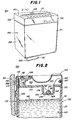
- Figure 1 is a front perspective view of a dispenser for fluid, and specifically liquid soap, forming a part of a fluid dispensing system made in accordance with and embodying the features of the present invention;
- Figure 2 is a fragmentary view in vertical section along the line 2-2 in Figure 1 and illustrating the internal construction of the soap dispenser, and particularly the refill well and associated structure thereof;
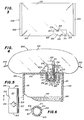
- Figure 3 is a plan view of a fluid injection pouch made in accordance with and embodying the principles of the present invention;
- Figure 4 is a view partly in section and illustrating the manner in which the fluid injection pouch of Figure 3 is utilized to refill the soap container in the soap dispenser of Figures 1 and 2;
- Figure 5 is a side elevational view of a first form of a tubular docking adaptor forming a part of the fluid injection pouch of Figure 3;
- Figure 6 is a view in horizontal section along the line of 6-6 of Figure 5;
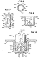
- Figure 7 is a side elevational view of a second form of tubular docking adaptor useful in the fluid injection pouch of the present invention;
- Figure 8 is a view in horizontal section along the line 8-8 of Figure 7;
- Figure 9 is a fragmentary view in vertical section on an enlarged scale through the refill well forming a part of the soap dispenser of Figures 1 and 2; and
- Figure 10 is a further enlarged view illustrating the co-operation between the tubular docking adaptor of Figure 7 and the wall of the associated injection pouch after insertion thereof into an associated refill well of a soap dispenser.
- Referring to Figures 1 and 2 of the drawings, there is illustrated a vessel, and specifically a
soap dispenser 100, with which afluid injection pouch 200 of the present invention is useful, and whichsoap dispenser 100 andinjection pouch 200 co-operate to provide the fluid dispensing system. - The
soap dispenser 100 includes amounting bracket 101 for use in mounting the dispenser on awall 50. - The
dispenser 100 also includes a soap container orhousing 130 which is preferably formed of plastic and is generally box-like in configuration. Thecontainer 130 includes a generallyrectangular front wall 131, a pair ofopposed side walls 132, arear wall 133 and a rectangular bottom wall (not shown), thecontainer 130 preferably being molded so that all the walls named are all formed integrally with one another. The walls of thecontainer 130 co-operate to define therewith a soap chamber, generally designated by thenumeral 140, which in use, is filled withliquid soap 141 to a predetermined level, such as 142. Liquid soap is withdrawn from thecontainer 130 by means of a pump assembly (not shown) which includes anoperating handle 151 provided at the lower end thereof with an enlargedgripping portion 153. Actuation of the pump assembly by means of theoperating handle 151 delivers a charge of soap from thesoap container 130 to the user's hand disposed beneath thecontainer 130 and in engagement with theoperating handle 151. - The
container 130 is also provided with atop wall 170 which is fixedly secured to the upper ends of thecontainer walls chamber 140. Formed in the upper surface of thetop wall 170 adjacent to the rear edge thereof is a narrow groove or recess 172. Also formed in thetop wall 170 is a deep cylindrical depending refill well 175 which is provided with a generallycylindrical side wall 174 closed at the bottom end thereof by acircular bottom wall 176. Theside wall 174 has aninner surface 177 that is essentially cylindrical in configuration. - Integral with the
bottom wall 176 of the refill well 175 and projecting upwardly therefrom substantially centrally thereof is apiercing member 180, thepiercing member 180 comprising a cruciform arrangement of four flat blades orwebs 181 respectively provided withknife edges 182 along the upper edges thereof which are inclined upwardly and inwardly to intersect at apoint 183 disposed about half way up the vertical extent of the refill well 175. Formed in thebottom wall 176 and disposed between adjacent ones of theblades 181 are four groups of refill perforations orapertures 184 which extend through thebottom wall 176. Each of therefill apertures 184 has a cross- sectional area such that viscous liquid soap of the type to be dispensed from thedispenser 100 will not pass through therefill apertures 184 by gravity alone, or at best, will pass only very slowly therethrough. Integral with thetop wall 170 and projecting inwardly therefrom adjacent to the front corners thereof are two lugs orears 185, each being provided with an arcuate recess defining a retaining surface in the forward edge thereof. - Pivotally secured to the inner surface of an upwardly extending
flange 110 of themounting bracket 100, as by arivet 188 extending through anopening 113, is a smallretaining plate 187, preferably formed of steel or the like. Theretaining plate 187 extends downwardly to a point adjacent to the bottom end of the inclined flange 109. In use, when thecontainer 130 is being mounted on themounting bracket 101, as the containerrear wall 133 is moved back against the bracket wall 102, theretaining plate 187 is pivoted upwardly out of the way to permit thetop wall 170 to pass thereunder, and then when the containerrear wall 133 is against the bracket wall 102, theretaining plate 187 is pivoted back down into engagement with thegroove 172 securely to hold thecontainer 130 in place and prevent it from tipping over. It will be understood that, when it is desired to demount thecontainer 130, theretaining plate 187 is pivoted back up to disengage it from thegroove 172 and permit removal of thecontainer 130. - The
dispenser 100 is also provided with acover plate 190 which includes atop wall 191, afront wall 192, a pair ofopposed side walls 193 and arear wall 194 all integrally connected in a unitary structure. Fixedly secured to the inner surface of thefront wall 192 adjacent the opposite side edges thereof are twoprojections 197 which are respectively adapted to be received in arcuate recesses for engagement with the retaining faces of thelugs 185 on thecontainer 130. Thecover plate 190 is dimensioned so as completely to cover thetop wall 170 of thecontainer 130, with thewalls 192 through 194 having a depth sufficient to accommodate the inclined flange 109 and the upwardly extendingflange 110 of themounting bracket 101. In use, theprojections 197 are inserted in the arcuate recesses of the lugs 186, and thecover plate 190 is then pivoted down into position completely covering the top of thecontainer 130, all as illustrated. - Preferably, the
cover plate 190 is provided with alock mechanism 198 which may be provided withlatch fingers 199 adapted to extend through apertures in themounting bracket flange 110, whereby the engagement of thelatch fingers 199 with thebracket flange 110 and the engagement of theprojections 197 with thelugs 185 co-operate securely to lock thecover plate 190 in place. It will be seen that when thus positioned on thecontainer 130, the outer surfaces of thewalls 192 through 194 are respectively substantially flush with the outer surfaces of thecontainer walls mounting bracket wall 101 to present substantially smooth uninterrupted outer surfaces for thedispenser 100 resulting in a clean, stylish appearance. - Referring to Figures 3 through 6 of the drawings, there is illustrated a first form of a
fluid injection pouch 200 for use with thedispenser 100 to provide a complete fluid dispensing system, thefluid injection pouch 200 more specifically being useful in replenishing the supply of viscousliquid soap 141 in thechamber 140 through the refill well 175. Thepouch 200 includes a flexibleplastic wall 201 that is initially tubular in shape, other shapes being also usable, and which after filling with viscousliquid soap 140, is sealed at each end as at 202 to provide a fluid-tight container 205 for viscous liquid soap. - Disposed within the
container 205 and in the fluid, and specificallyliquid soap 141 disposed therein, is atubular docking adaptor 210, see particularly Figures 5 and 6. Theadaptor 210 is cylindrical in shape, circular in cross-section, and includes an outercylindrical wall 211 extending the length thereof, and a cylindricalinner wall 212 also extending the length thereof. It will be appreciated that theadaptor 210 may have a cross-section of a different shape. Theadaptor 210 terminates atends 213 at each end thereof, theends 213 being disposed normal to the longitudinal axis of thetubular docking adaptor 210. The outer size or diameter of theouter wall 211 is slightly less than the inner size or diameter of theinner surface 177 or the refill well 175, and more specifically, the difference in the diameters is slightly less than the thickness of the material forming thepouch wall 201, so that when the parts are in the positions illustrated in Figure 4, a fluid-tight seal is provided between the inner surface of thepouch wall 201 and the outer surface of theouter wall 211, and between the outer surface of thepouch wall 201 and theinner surface 177 of the refill well 175. The inner size or diameter of theinner wall 212 is slightly greater than the lateral extent of thepiercing member 180, and specifically theblades 181, so as to fit thereover. With the parts in the positions illustrated in Figure 4, a portion of thepouch wall 201 has been forced by theadaptor 210 over thepiercing member 180 so as to puncture thepouch wall 201 and to permit discharge of the contents of thepouch 200 through therefill apertures 184 in the bottom of the refill well 175. - There are provided in the
adaptor 210 two diamond-shaped drain openings 215 which are spaced from theadjacent end 213 by an equal and predetermined distance. Each of the 'diamond-shaped openings 215 has fouredges 216, two of theedges 216 providing an intersection at apoint 217 that is disposed a predetermined distance from theadjacent end 213 of theadaptor 210. More specifically, thepoint 217 is disposed away from the adjacent adaptor end 213 a distance such thatpoint 217 is disposed well below the upper surface of thetop wall 170, and well into the refill well 175 when the parts are in the operative positions illustrated in Figure 4. This arrangement of thedrain openings 215 assures that the last portions of viscous liquid soap in thepouch 200 are injected into thechamber 140 of thedispenser 100. - It is pointed out that the
adaptor 210 is essentially symmetrical about a plane normal to the longitudinal axis of theadaptor 210 and intersecting the longitudinal midpoint of theadaptor 210. As a consequence, either of theends 213 on theadaptor 210 may be inserted into the well 175 to empty the contents of thepouch 200 into thechamber 140. It also is noted that thedrain openings 215 are circumferentially displaced 90° with respect to each other so as to strengthen theadaptor 210 as compared to a configuration wherein thedrain openings 215 were in longitudinal alignment. It will be appreciated that thedrain openings 215 can be circumferentially displaced greater than 90° and up to 180° while retaining this desirable characteristic of maximizing the mechanical strength of thetubular docking adaptor 210. - In a constructional example of the
pouch 200, thewall 201 is formed of a plastic, a preferred plastic being polyethylene plastic, having a thickness of .0038 cm (about 1.5 mils). The thickness of the plastic may vary from as little as .0025 cm (1 mil) up to as much as .0127 cm (5 mils) while retaining the desirable characteristics of thepouch 200. The portion of thewall 201 forming thecontainer 205 is preferably about 15.2 cm x 17.7 cm (about 6 inchesx7 inches), and theseals 202 are preferably about 0.3 cm (about 1/8 inch) wide. Other materials may be used in forming thewall 201, such as thin gage metal, fluid-proof paper and the like. Thetubular docking adaptor 210 is also preferably formed of plastic, a preferred plastic being polyethylene plastic. The diameter of theouter wall 211 is about 1.9 cm (about 3/4 inch), while the diameter of the inner wall is slightly greater than about 1.27 cm (about 1/2 inch), and the length of theadaptor 210 is about 7.6 cm (3 inches) while the longitudinal point-to-point distance of thedrain openings 215 in the longitudinal direction is about 1.27 cm (about 1/2 inch). - The
fluid injection pouch 200 may be used to replenish all types of fluids, and is specifically not limited to the use to replenish liquid soap. Other suitable fluids useful in the present invention are automotive oil, windshield-wiper fluid, medical fluids, industrial metal cutting lubricants, chemical additives, etc. - In the use of the pouch to replenish the
soap 141 in thechamber 140, the user first lifts thepouch 200 in the condition illustrated in Figure 3, and through thepouch wall 201 grasps thetubular docking adaptor 210 adjacent to one end thereof, folding a portion of thewall 201 over theother end 213. Thecover plate 190 has heretofore been removed from thedispenser 100 so as to expose the refill well 175. The aforementionedother end 213 of theadaptor 210 is then forcefully inserted into the refill well 175. The portion of thepouch wall 201 covering theother end 213 is then pressed against the piercingmember 180 and is pierced thereby as theadaptor 210 is driven home into the refill well 175, the parts eventually reaching the positions illustrated in Figure 4. At this time, a portion of thewall 201 has been pierced as at 206 (see Figure 4), thus providing the communication between the interior of thepouch container 205 and therefill apertures 184. It is noted that the portion of thepouch wall 201 surrounding the engaged end of theadaptor 210 assists in forming a seal between theouter wall 211 and theinner surface 177 of the refill well 175. The user next squeezes thepouch 200 to force the contents thereof under pressure through theadaptor 210 and then through therefill apertures 184 and into thechamber 140. As was indicated above, the viscous liquid soap will not flow through therefill apertures 184 by gravity, whereby it is necessary for the user forcefully to squeeze thepouch 200 to cause the necessary flow through therefill apertures 184. Thedrain opening 215 is disposed partially in the refill well 175 facilitates the expulsion of the final portions of the contents of thepouch 200 therefrom and through therefill apertures 184 and into thechamber 140. When thepouch 200 has been emptied, theadaptor 210 is grasped through thewall 201 and is pulled upwardly to remove theadaptor 210 and the associated portions of thepouch wall 201 from therefill wall 175. Theentire pouch 200, including theadaptor 210 is then discarded. - It will be appreciated that the
pouch 200 can be stored in a minimum of space, since thewall 201 thereof can deform so as closely to pack a container holding a plurality of thepouches 200. Furthermore, theadaptor 210 is disposed completely within thepouch 200 and thesoap 141 contained therein, whereby there is no objectionable protrusion which interferes with packing and storing of thepouch 200. In use, the construction of thepouch 200 and itsadaptor 210 assure easy and tidy replenishing of the viscous soap in thecontainer 140 by injecting the contents of thepouch 200 through itsadaptor 210 and thepierced portion 206 of thepouch wall 201, and thence through therefill apertures 184 and into thecontainer 140. Since thepouch 200 and all the components thereof including theadaptor 210 are disposable, there is a minimum of difficulty experienced by the user in disposing of theempty pouch 200 and its associated parts. - After the contents of the
pouch 200 have been injected into thecontainer 140, thecover plate 190 is replaced, and preferably locked in position by means of thelock mechanism 198. Soap can then again be dispensed from thedispenser 100 by the user actuating the operating handle 151 of the pump assembly. As soon as the level of soap falls to the point where it must be replenished, the refill operation using anotherpouch 200 and itsadaptor 210 is repeated as explained above. - Referring to Figures 7 to 10 of the drawings, there is illustrated a second preferred embodiment of an
adaptor 310 for use in apouch 200 of the type discussed above. Theadaptor 310 is generally cylindrical in shape, circular in cross-section, and includes an outercylindrical wall 311 and an innercylindrical wall 312 extending the length thereof. Theadaptor 310 terminates at ends 313 at each end thereof, theends 313 being disposed normal to the longitudinal axis of thetubular docking adaptor 310. The outer diameter of theouter wall 311 is slightly less than the inner diameter of theinner surface 177 of the refill well 175, and more specifically, the difference in the diameters is slightly less than the thickness of the material forming thepouch 200, so that when the parts are in the position illustrated in Figure 10, a fluid-tight seal is provided between the inner surface of thepouch wall 201 and the outer surface of theouter wall 311, and between the outer surface of thepouch wall 201 and theinner surface 177 of the refill well 175. The inner diameter of theinner wall 312 is slightly greater than the lateral extent of the piercingmember 180 and specifically theblades 181, so as to fit thereover. - In order better to seal the space between the outer surface of the
outer wall 311 and theinner surface 177 of the refill well 175, annular flexible sealing means is provided adjacent to eachend 313 of theadaptor 310 in the form sealing ribs orflanges 320. Theflanges 320 are separated bygrooves 322 and theinnermost flanges 320 are separated from theouter wall 311 by slightlywider grooves 323. Theflanges 320 have relatively small longtudinal dimensions and the material of construction of theadaptor 310 is such that theflanges 320 are flexible and resilient to accomplish the sealing function thereof. With the parts in the position illustrated in Figure 10, a portion of thepouch wall 201 has been forced by theadaptor 310 over the piercingmember 180 so as to puncture thepouch wall 201 and to permit discharge of the contents of thepouch 200 through therefill apertures 184 in the bottom of refill well 175. The sealingflanges 320 serve to maintain a fluid-tight connection between theadaptor 310 and theside wall 174 of the refill well 175.. - there are provided in the
adaptor 310 four oval-shapeddrain openings 315 that extend from adjacent to oneend 313 to adjacent to theother end 313. Each of the oval-shapedopenings 315 has longitudinally extendingside edges 316 joined at each end by arounded end 317. Each of the rounded ends 317 is spaced from theadjacent adaptor end 313 by an equal and predetermined distance. More specifically, each of the drain opening ends 317 is disposed away from the adjacent adaptor end 313 a distance such that therounded end 317 is disposed well below the upper surface of thetop wall 170, and well into the refill well 175 when the parts are in the operative positions illustrated in Fig. 10. This arrangement of thedrain openings 315 assures that the last portions of the viscous liquid soap in thepouch 200 are injected into thechamber 140 of thedispenser 100. - It is pointed out that the
adaptor 310 is essentially symmetrical about a plane normal to the longitudinal axis of theadaptor 310 and intersecting the longitudinal midpoint of theadaptor 310. As a consequence, either of theends 313 on theadaptor 310 may be inserted into the well 175 to empty the contents of thepouch 200 into thechamber 140. It also is noted that thedrain openings 315 are circumferentially equidistantly displaced with respect to each other so as to strengthen theadaptor 310 as compared to any other configuration thereof. - In a constructional example of the
tubular docking adaptor 310, it is preferably formed of plastic, the preferred plastic being polyethylene plastic. The diameter of theouter wall 311 is about 1.9 cm (about 3/4 inch) while the diameter of the inner wall is about 1.6 cm (about 5/8 inch), and the length of theadaptor 310 is about 7.6 cm (about 3 inches). Thedrain openings 315 have a longitudinal extent of 1.9 cm (about 3/4 inch) and a width at the greatest width thereof of .64 cm (about 1/4 inch). Each of the sealingflanges 320 has a longitudinal extent of .076 cm (about 0.03 inches), thegrooves 322 have a longitudinal extent of about .25 cm (about 0.10 inches), and thegrooves 323 have a longitudinal extent of about .40 cm (about 0.16 inches). Thegrooves - The use of a
pouch 200 provided with theadaptor 310 to replenish thesoap 141 in thechamber 140 is the same as that described above with respect to apouch 200 with anadaptor 210 therein. The only significant difference between the operation of theadaptor 210 and theadaptor 310 is the slightly better liquid-tight seal provided by the sealingflanges 320 on theadaptor 310. Apouch 200 provided with theadaptor 310 has all of the advantages and characteristics discussed above with respect to apouch 200 provided with anadaptor 210.
Claims (9)
Priority Applications (1)
| Application Number | Priority Date | Filing Date | Title |
|---|---|---|---|
| AT79302936T ATE2713T1 (en) | 1979-02-07 | 1979-12-18 | SYSTEM FOR DISPENSING LIQUID. |
Applications Claiming Priority (2)
| Application Number | Priority Date | Filing Date | Title |
|---|---|---|---|
| US10013 | 1979-02-07 | ||
| US06/010,013 US4322019A (en) | 1979-02-07 | 1979-02-07 | Fluid injection pouch and dispensing system incorporating the same |
Publications (2)
| Publication Number | Publication Date |
|---|---|
| EP0014805A1 EP0014805A1 (en) | 1980-09-03 |
| EP0014805B1 true EP0014805B1 (en) | 1983-03-09 |
Family
ID=21743317
Family Applications (1)
| Application Number | Title | Priority Date | Filing Date |
|---|---|---|---|
| EP79302936A Expired EP0014805B1 (en) | 1979-02-07 | 1979-12-18 | System for dispensing fluid |
Country Status (15)
| Country | Link |
|---|---|
| US (1) | US4322019A (en) |
| EP (1) | EP0014805B1 (en) |
| JP (1) | JPS55107691A (en) |
| AR (1) | AR225431A1 (en) |
| AT (1) | ATE2713T1 (en) |
| AU (1) | AU5399079A (en) |
| BR (1) | BR8000740A (en) |
| CA (1) | CA1134325A (en) |
| DE (1) | DE2965016D1 (en) |
| DK (1) | DK5780A (en) |
| ES (1) | ES257490Y (en) |
| FI (1) | FI65204C (en) |
| NO (1) | NO800025L (en) |
| NZ (1) | NZ192375A (en) |
| ZA (1) | ZA796680B (en) |
Families Citing this family (35)
| Publication number | Priority date | Publication date | Assignee | Title |
|---|---|---|---|---|
| US4808346A (en) * | 1972-07-20 | 1989-02-28 | Strenger & Associates | Carbonated beverage dispensing apparatus and method |
| DE3112151A1 (en) * | 1980-04-02 | 1982-03-18 | Appor Ltd., Milford, Derby | DISPENSER OR DISPENSER |
| US4534669A (en) * | 1983-03-24 | 1985-08-13 | Sani-Fresh International, Inc. | Cleaning system with cartridge having valve means |
| US4567918A (en) * | 1983-03-31 | 1986-02-04 | Flexcel International, Inc. | Liquid reservoir and method of dispensing a liquid therefrom by means of a vehicle |
| US4676280A (en) * | 1986-03-18 | 1987-06-30 | Flexcel International, Inc. | Liquid reservoir and method of using a vehicle to dispense liquid therefrom |
| US4759472A (en) * | 1986-04-17 | 1988-07-26 | Hays Macfarland & Associates | Container having a pressure-rupturable seal for dispensing contents |
| GB2208640B (en) * | 1987-02-12 | 1991-06-05 | Ici Plc | Method for introducing additive into a closed container |
| GB2200888B (en) * | 1987-02-12 | 1991-05-29 | Ici Plc | A closed container into which additive can be introduced |
| US4846236A (en) * | 1987-07-06 | 1989-07-11 | Deruntz William R | Bottled water dispenser insert |
| AU5823890A (en) * | 1989-06-21 | 1991-01-08 | Gilbert L. Cooper | Improvements in dispensing flowable contents from frangible packaging |
| GB8922478D0 (en) * | 1989-10-05 | 1989-11-22 | Procter & Gamble | Flowable product package incorporating a refill facilitating pouring spout |
| US5125536A (en) * | 1991-06-03 | 1992-06-30 | Winder D H | Fluid transferring device with moveable cutter |
| US5190081A (en) * | 1991-06-03 | 1993-03-02 | Winder D H | Device for transferring fluid from a bag into a fluid reservoir |
| US5343903A (en) * | 1991-06-03 | 1994-09-06 | Winder D Howard | Method of transferring a liquid to a reservoir using a storage bag having a passage therethrough |
| US5732853A (en) * | 1992-11-03 | 1998-03-31 | Bentfield Europe B.V. | Dosing unit comprising a dispensing device and a container bag unit |
| GB2279069B (en) * | 1993-06-19 | 1997-03-05 | Archibald Gerard Mciver | Container |
| DE19709201A1 (en) * | 1997-03-06 | 1998-09-10 | Weigert Chem Fab | Kit and refill bag for dosing a powder |
| US5967197A (en) * | 1998-04-06 | 1999-10-19 | Shown; Richard L. | Drinking water delivery system |
| US7066356B2 (en) * | 2002-08-15 | 2006-06-27 | Ecolab Inc. | Foam soap dispenser for push operation |
| SE0203129D0 (en) * | 2002-10-24 | 2002-10-24 | Asept Int Ab | Connection device |
| WO2005087058A1 (en) * | 2004-03-12 | 2005-09-22 | Perez Ordonez Alejandro | Jug comprising a water intake device |
| US7753087B2 (en) * | 2005-10-19 | 2010-07-13 | Kutol Products Company, Inc. | Product dispensing system |
| JP5414032B2 (en) * | 2009-03-10 | 2014-02-12 | 日本クロージャー株式会社 | Refillable pouch spout |
| US9717354B2 (en) | 2013-10-11 | 2017-08-01 | Gehl Foods, Llc | Food product dispenser and valve |
| US10034584B2 (en) | 2014-03-04 | 2018-07-31 | Gojo Industries, Inc. | Fluid dispenser and fluid refill system for fluid dispenser |
| CA2959161A1 (en) | 2014-08-29 | 2016-03-03 | Gehl Food, Llc | Food product dispenser and valve |
| USD792164S1 (en) | 2014-08-29 | 2017-07-18 | Gehl Foods, Llc | Food dispenser |
| USD718621S1 (en) | 2014-08-29 | 2014-12-02 | Gehl Foods, Inc. | Fitment for interconnection between product packaging and a product dispenser |
| CA161168S (en) | 2014-08-29 | 2015-12-01 | Gehl Foods Inc | Valve |
| US11058261B2 (en) | 2015-07-15 | 2021-07-13 | Gojo Industries, Inc. | Bulk refill protection sensor for dispensing system |
| USD795029S1 (en) | 2015-08-28 | 2017-08-22 | Gehl Foods, Llc | Tool |
| USD798106S1 (en) | 2015-08-28 | 2017-09-26 | Gehl Foods, Llc | Valve |
| EP3721765B1 (en) | 2016-01-05 | 2023-03-29 | GOJO Industries, Inc. | Fluid dispenser and fluid dispenser system with means for detecting improper refilling and method for detecting improper refilling of a fluid dispenser |
| AU2018397599B2 (en) | 2017-12-29 | 2021-09-09 | Colgate-Palmolive Company | Dispenser system |
| US20210387785A1 (en) * | 2020-06-11 | 2021-12-16 | Lorris Joseph Jackson | Wearable Pressure Controlled Release Dispenser Device and Method |
Family Cites Families (13)
| Publication number | Priority date | Publication date | Assignee | Title |
|---|---|---|---|---|
| US3128913A (en) * | 1964-04-14 | Container spout having its outlet passage sealed by | ||
| US2849321A (en) * | 1955-07-16 | 1958-08-26 | Glaces Gervais Soc | Container for liquid and semi-liquid foodstuffs |
| US3257036A (en) * | 1963-05-06 | 1966-06-21 | Leeds | Pressure discharge container |
| US3255923A (en) * | 1964-02-03 | 1966-06-14 | Lacto Seal Inc | Disposable liquid storage and dispensing device |
| US3220588A (en) * | 1964-09-17 | 1965-11-30 | Lipari Michael | Compartmental dispensing receptacle with accessories |
| GB1295834A (en) * | 1969-02-04 | 1972-11-08 | ||
| US3596801A (en) * | 1969-07-22 | 1971-08-03 | Henry C Barnack | Disposable instant mix all container |
| NL7208451A (en) * | 1971-06-26 | 1972-12-28 | ||
| US3995773A (en) * | 1974-03-06 | 1976-12-07 | Arctic Pac, Inc. | Flexible liquid containing and dispensing device |
| IT1022669B (en) * | 1974-10-07 | 1978-04-20 | Macchi Cassia Antonio | PARTICULARLY DISTRIBUTOR FOR LIQUID SOAP |
| AT336193B (en) * | 1975-02-05 | 1977-04-25 | Gss Ges Fur Sanitare Spendersy | DEVICE FOR THE DOSABLE DISPENSING OF LIQUID |
| US4146156A (en) * | 1976-02-03 | 1979-03-27 | Steiner American Corporation | Soap dispensing system |
| IT1087674B (en) * | 1977-10-06 | 1985-06-04 | Steiner Co Int Sa | SOAP DISTRIBUTION SYSTEM |
-
1979
- 1979-02-07 US US06/010,013 patent/US4322019A/en not_active Expired - Lifetime
- 1979-12-10 ZA ZA00796680A patent/ZA796680B/en unknown
- 1979-12-12 NZ NZ192375A patent/NZ192375A/en unknown
- 1979-12-18 EP EP79302936A patent/EP0014805B1/en not_active Expired
- 1979-12-18 DE DE7979302936T patent/DE2965016D1/en not_active Expired
- 1979-12-18 AT AT79302936T patent/ATE2713T1/en not_active IP Right Cessation
- 1979-12-19 AU AU53990/79A patent/AU5399079A/en not_active Abandoned
- 1979-12-28 CA CA000342741A patent/CA1134325A/en not_active Expired
-
1980
- 1980-01-04 NO NO800025A patent/NO800025L/en unknown
- 1980-01-07 JP JP48580A patent/JPS55107691A/en active Granted
- 1980-01-07 DK DK5780A patent/DK5780A/en not_active Application Discontinuation
- 1980-01-07 ES ES1980257490U patent/ES257490Y/en not_active Expired
- 1980-01-09 FI FI800066A patent/FI65204C/en not_active IP Right Cessation
- 1980-02-01 AR AR278830A patent/AR225431A1/en active
- 1980-02-06 BR BR8000740A patent/BR8000740A/en unknown
Also Published As
| Publication number | Publication date |
|---|---|
| NO800025L (en) | 1980-08-08 |
| CA1134325A (en) | 1982-10-26 |
| ES257490Y (en) | 1982-05-01 |
| US4322019A (en) | 1982-03-30 |
| DE2965016D1 (en) | 1983-04-14 |
| ATE2713T1 (en) | 1983-03-15 |
| ES257490U (en) | 1981-11-01 |
| BR8000740A (en) | 1980-10-14 |
| FI800066A (en) | 1980-08-08 |
| ZA796680B (en) | 1980-11-26 |
| DK5780A (en) | 1980-08-08 |
| JPS6356115B2 (en) | 1988-11-07 |
| NZ192375A (en) | 1983-11-18 |
| JPS55107691A (en) | 1980-08-18 |
| FI65204B (en) | 1983-12-30 |
| AR225431A1 (en) | 1982-03-31 |
| FI65204C (en) | 1984-04-10 |
| EP0014805A1 (en) | 1980-09-03 |
| AU5399079A (en) | 1980-08-14 |
Similar Documents
| Publication | Publication Date | Title |
|---|---|---|
| EP0014805B1 (en) | System for dispensing fluid | |
| US4576313A (en) | Fluid refill pouch and dispenser | |
| EP0001595B1 (en) | Liquid soap dispensing system and liquid soap dispenser | |
| US4345627A (en) | Soap dispensing system | |
| US4391308A (en) | Soap dispensing system | |
| EP3672463B1 (en) | Dispenser system | |
| US4316555A (en) | System for dispensing fluids | |
| US4440316A (en) | Combined piercer and valve for flexible bag | |
| EP1116688B1 (en) | A device for the delivery of products | |
| JPH0680169A (en) | Multi-cavity type distribution refilling cartridge | |
| US20020030063A1 (en) | Multiple-compartment container | |
| US5279797A (en) | Disposable liquid reagent cartridge and receptacle therefor | |
| CA2045034C (en) | Bottle refilling apparatus | |
| US20220119169A1 (en) | Dispensing system | |
| EP0046754A1 (en) | Combined piercer and valve for flexible bag. | |
| US3905370A (en) | Disposable douche product | |
| EP1301357A2 (en) | Non-spill chalk line and measured refill cartridge | |
| US6675842B1 (en) | Fluid delivery system | |
| JPH10157747A (en) | Bag-form container | |
| HUT73298A (en) | Refillable package | |
| WO1999019222A1 (en) | Improved dispenser bag | |
| GB2152590A (en) | Dispensing apparatus | |
| CN217448074U (en) | Main machine of tooth flushing device and tooth flushing device | |
| CA1206925A (en) | Container with reciprocable dispensing tube | |
| GB2612842A (en) | Improvements in refillable liquid dispenser devices |
Legal Events
| Date | Code | Title | Description |
|---|---|---|---|
| PUAI | Public reference made under article 153(3) epc to a published international application that has entered the european phase |
Free format text: ORIGINAL CODE: 0009012 |
|
| AK | Designated contracting states |
Designated state(s): AT BE CH DE FR GB IT LU NL SE |
|
| 17P | Request for examination filed | ||
| ITCL | It: translation for ep claims filed |
Representative=s name: ING. C. GREGORJ S.P.A. |
|
| TCAT | At: translation of patent claims filed | ||
| DET | De: translation of patent claims | ||
| GRAA | (expected) grant |
Free format text: ORIGINAL CODE: 0009210 |
|
| AK | Designated contracting states |
Designated state(s): AT BE CH DE FR GB IT LU NL SE |
|
| PG25 | Lapsed in a contracting state [announced via postgrant information from national office to epo] |
Ref country code: SE Effective date: 19830309 Ref country code: NL Effective date: 19830309 Ref country code: IT Free format text: LAPSE BECAUSE OF FAILURE TO SUBMIT A TRANSLATION OF THE DESCRIPTION OR TO PAY THE FEE WITHIN THE PRESCRIBED TIME-LIMIT;WARNING: LAPSES OF ITALIAN PATENTS WITH EFFECTIVE DATE BEFORE 2007 MAY HAVE OCCURRED AT ANY TIME BEFORE 2007. THE CORRECT EFFECTIVE DATE MAY BE DIFFERENT FROM THE ONE RECORDED. Effective date: 19830309 Ref country code: BE Effective date: 19830309 Ref country code: AT Free format text: LAPSE BECAUSE OF NON-PAYMENT OF DUE FEES Effective date: 19830309 |
|
| REF | Corresponds to: |
Ref document number: 2713 Country of ref document: AT Date of ref document: 19830315 Kind code of ref document: T |
|
| REF | Corresponds to: |
Ref document number: 2965016 Country of ref document: DE Date of ref document: 19830414 |
|
| ET | Fr: translation filed | ||
| NLV1 | Nl: lapsed or annulled due to failure to fulfill the requirements of art. 29p and 29m of the patents act | ||
| PG25 | Lapsed in a contracting state [announced via postgrant information from national office to epo] |
Ref country code: LU Free format text: LAPSE BECAUSE OF NON-PAYMENT OF DUE FEES Effective date: 19831231 |
|
| GBPC | Gb: european patent ceased through non-payment of renewal fee | ||
| REG | Reference to a national code |
Ref country code: GB Ref legal event code: 728C |
|
| REG | Reference to a national code |
Ref country code: GB Ref legal event code: 728A |
|
| ITTA | It: last paid annual fee | ||
| PGFP | Annual fee paid to national office [announced via postgrant information from national office to epo] |
Ref country code: DE Payment date: 19930222 Year of fee payment: 14 |
|
| PGFP | Annual fee paid to national office [announced via postgrant information from national office to epo] |
Ref country code: FR Payment date: 19931022 Year of fee payment: 15 |
|
| PG25 | Lapsed in a contracting state [announced via postgrant information from national office to epo] |
Ref country code: DE Effective date: 19940901 |
|
| PGFP | Annual fee paid to national office [announced via postgrant information from national office to epo] |
Ref country code: GB Payment date: 19941221 Year of fee payment: 16 |
|
| PGFP | Annual fee paid to national office [announced via postgrant information from national office to epo] |
Ref country code: CH Payment date: 19950227 Year of fee payment: 16 |
|
| PG25 | Lapsed in a contracting state [announced via postgrant information from national office to epo] |
Ref country code: FR Effective date: 19950831 |
|
| REG | Reference to a national code |
Ref country code: FR Ref legal event code: ST |
|
| PG25 | Lapsed in a contracting state [announced via postgrant information from national office to epo] |
Ref country code: GB Effective date: 19951218 |
|
| PG25 | Lapsed in a contracting state [announced via postgrant information from national office to epo] |
Ref country code: CH Effective date: 19951231 |
|
| GBPC | Gb: european patent ceased through non-payment of renewal fee |
Effective date: 19951218 |
|
| REG | Reference to a national code |
Ref country code: CH Ref legal event code: PL |
|
| PLBE | No opposition filed within time limit |
Free format text: ORIGINAL CODE: 0009261 |
|
| STAA | Information on the status of an ep patent application or granted ep patent |
Free format text: STATUS: NO OPPOSITION FILED WITHIN TIME LIMIT |