EP0013632B1 - Sorting apparatus for sorting sheets - Google Patents
Sorting apparatus for sorting sheets Download PDFInfo
- Publication number
- EP0013632B1 EP0013632B1 EP80300130A EP80300130A EP0013632B1 EP 0013632 B1 EP0013632 B1 EP 0013632B1 EP 80300130 A EP80300130 A EP 80300130A EP 80300130 A EP80300130 A EP 80300130A EP 0013632 B1 EP0013632 B1 EP 0013632B1
- Authority
- EP
- European Patent Office
- Prior art keywords
- sheet
- receiving members
- groups
- cam member
- sheets
- Prior art date
- Legal status (The legal status is an assumption and is not a legal conclusion. Google has not performed a legal analysis and makes no representation as to the accuracy of the status listed.)
- Expired
Links
- 230000002441 reversible effect Effects 0.000 claims 1
- 239000000463 material Substances 0.000 description 21
- 230000032258 transport Effects 0.000 description 9
- 239000002245 particle Substances 0.000 description 8
- 239000000843 powder Substances 0.000 description 6
- 230000000712 assembly Effects 0.000 description 3
- 238000000429 assembly Methods 0.000 description 3
- 238000004140 cleaning Methods 0.000 description 3
- 238000011161 development Methods 0.000 description 3
- 230000003287 optical effect Effects 0.000 description 3
- 238000012546 transfer Methods 0.000 description 3
- 238000000034 method Methods 0.000 description 2
- 238000012545 processing Methods 0.000 description 2
- 229910001370 Se alloy Inorganic materials 0.000 description 1
- BUGBHKTXTAQXES-UHFFFAOYSA-N Selenium Chemical class [Se] BUGBHKTXTAQXES-UHFFFAOYSA-N 0.000 description 1
- XAGFODPZIPBFFR-UHFFFAOYSA-N aluminium Chemical compound [Al] XAGFODPZIPBFFR-UHFFFAOYSA-N 0.000 description 1
- 229910052782 aluminium Inorganic materials 0.000 description 1
- 238000013459 approach Methods 0.000 description 1
- 239000008187 granular material Substances 0.000 description 1
- 238000005286 illumination Methods 0.000 description 1
- 239000000203 mixture Substances 0.000 description 1
- 239000000758 substrate Substances 0.000 description 1
- 239000000725 suspension Substances 0.000 description 1
- 230000001960 triggered effect Effects 0.000 description 1
Images



Classifications
-
- B—PERFORMING OPERATIONS; TRANSPORTING
- B65—CONVEYING; PACKING; STORING; HANDLING THIN OR FILAMENTARY MATERIAL
- B65H—HANDLING THIN OR FILAMENTARY MATERIAL, e.g. SHEETS, WEBS, CABLES
- B65H39/00—Associating, collating, or gathering articles or webs
- B65H39/10—Associating articles from a single source, to form, e.g. a writing-pad
- B65H39/11—Associating articles from a single source, to form, e.g. a writing-pad in superposed carriers
-
- B—PERFORMING OPERATIONS; TRANSPORTING
- B65—CONVEYING; PACKING; STORING; HANDLING THIN OR FILAMENTARY MATERIAL
- B65H—HANDLING THIN OR FILAMENTARY MATERIAL, e.g. SHEETS, WEBS, CABLES
- B65H2403/00—Power transmission; Driving means
- B65H2403/50—Driving mechanisms
- B65H2403/51—Cam mechanisms
- B65H2403/511—Cam mechanisms involving cylindrical cam, i.e. cylinder with helical groove at its periphery
-
- B—PERFORMING OPERATIONS; TRANSPORTING
- B65—CONVEYING; PACKING; STORING; HANDLING THIN OR FILAMENTARY MATERIAL
- B65H—HANDLING THIN OR FILAMENTARY MATERIAL, e.g. SHEETS, WEBS, CABLES
- B65H2408/00—Specific machines
- B65H2408/10—Specific machines for handling sheet(s)
- B65H2408/11—Sorters or machines for sorting articles
- B65H2408/113—Sorters or machines for sorting articles with variable location in space of the bins relative to a stationary in-feed path
Definitions
- This invention relates to sorting apparatus for sorting sheets.
- sorting systems included large and bulky bin modules with a multitude of trays arranged for movement relative to the sheet path for increased storage.
- One typical sorter employs tray members which are spaced apart and extend in a linear row.
- Another type of sorting apparatus has trays extending radially outwardly from the axis of rotation.
- Copy sheets may be collected in the bins of the sorter in a number of ways. The most common technique is to utilize the sheet transport to advance the copy sheets past the bin openings and deflection fingers to guide the sheets from the transport into the respective bin. Alternatively, the deflection fingers could move from bin to bin so as to deflect the copy sheets into the selected bin. Still yet another approach is to move the bins past the sheet ejecting portion of the transport. In this manner, the bins of the sorting apparatus collected the various sheets forwarded thereto.
- sorting systems of this type frequently had limitations in the number of copy sheets that could be collected or their size was extremely large and did not readily lend itself to compact printing machines.
- U.S. Patent No. 3,273,882 discloses a sorter having a plurality of stationary shelves. Tapes advance the sheets past the shelves. A column of deflecting fingers are disposed in front of the shelves. The fingers are sequentially triggered to deflect successive sheets into the respective shelves.
- U.S. Patent No. 3,395,913 describes a sorter in which sheets are advanced by rollers to a diverter comprising a gate. A cam actuates the appropriate gate to guide the sheets into the selected catch tray.
- U.S. Patent No. 3,516,654 discloses a sorter having a plurality of pockets and a ramp for guiding the sheets into the pockets. The delivery end of the ramp is indexed to successive pockets. After a first stack of pockets has had sheets delivered thereto, a second stack of pockets is moved into the sheet delivery position and the ramp returned to its initial position.
- U.S. Patent No. 3,561,753 describes a sorter having a plurality of stationary bins.
- a vacuum conveyor transports the sheets past the bins.
- a deflector also travels past the bins.
- the control system positions the deflector at the selected bin and the deflector strips the sheet from the transport and guides it into the bin.
- U.S. Patent No. 3,740,050 describes a sorter employing a plurality of magazines having fingers for guiding the sheets into the respective magazine.
- U.S. Patent No. 3,848,867 describes a sorter in which a sheet advances along a path past the entrance to various stations. The sheets are deflected out of the path into a station by a movable deflector that traverses vertically past the stations.
- U.S. Patent No. 3,995,748 discloses a sorter having two sets of vertical bins of trays. The bins move vertically so as to be successively aligned with the inlet and discharge stations. After one set of bins has been filled with copy sheets, the sorter rotates positioning the unfilled set of bins on the inlet side and the filled set of bins at the discharge side.
- U.S. Patent No. 3,788,640 discloses a cam- operated sorting apparatus according to the preamble of claim 1 comprising at least two groups of sheet receiving members, each of said groups of sheet receiving members comprising a series of individual sheet receiving members arranged to receive and discharge sheets therefrom; a sheet loading station arranged to advance sheets into said individual sheet receiving members of said groups of sheet receiving members; at least two sheet unloading stations arranged to have one of said groups of sheet receiving members positioned thereat for removing the sheets therefrpm; and means coupled to said groups of sheet receiving members for moving at least one of said groups of sheet receiving members to one of the unloading stations with one of the other groups of sheet receiving members being moved to said sheet loading station so as to bring said individual sheet receiving members into position for receiving sheets at said sheet loading station, thereby loading and unloading each of said two groups of sheet receiving members.
- a sorting apparatus is characterised in that each of said at least two groups of sheet receiving members is dedicated only to a respective one of said at least two unloading stations while using the common loading station and said moving means is adapted to move said at least two groups of sheet receiving members so that as one group is moved from the loading station to its respective unloading station another group is moved from its respective unloading station to the loading station.
- the reproduction system includes a copying machine, preferably an electrophotographic printing machine, designated generally by the reference numeral 12, and a sorting apparatus, indicated generally by the reference numeral 14.
- Electrophotographic printing machine 12 is capable of producing simplex or duplex copies at the option of the machine operator.
- Printing machine 12 has a platen for receiving documents to be reproduced and a control panel 18 for selecting different modes of operation such as simplex and duplex copying and the number of copies required to be reproduced.
- the electrophotographic printing machine 12 is coupled to sorting apparatus 14.
- Sorting apparatus 14 has two groups of sheet receiving members or trays.
- one group of trays designated generally by the reference numeral 20, is in the sheet loading position while the other group of trays, designated generally by the reference numeral 22, is in the sheet unloading position.
- each group of trays comprises ten trays.
- the next group of trays 20 is moved from the sheet unloading station to the sheet loading station.
- sheets are loaded into the second group of trays 20, sheets are unloaded from the first group of trays 22.
- FIG. 2 an operator is shown unloading sets of collated copies from the first group of trays 22.
- This group of trays 22 has advanced to the sheet unloading station.
- the second group of trays 20 has advanced to the sheet loading position and copies are being advanced to the respective trays thereof.
- the operator removes the collated sets from the front of the copy machine.
- the sheets are loaded into the second group of trays 20 from the side thereof.
- FIG. 3 there is shown schematically the structure of electrophotographic printing machine 12.
- the various processing stations employed in the printing machine are shown schematically and their operation briefly described with reference thereto.
- electrophotographic printing machine 12 includes a drum 24 having the outer periphery thereof coated with a suitable photoconductive material.
- drum 24 is made from a conductive substrate, such as aluminum, having the photoconductive material, e.g. a selenium alloy, deposited thereon.
- Drum 24 rotates in the direction of arrow 26 to pass through the various processing stations disposed thereabout.
- drum 24 moves a portion of the photoconductive surface through charging station 28.
- a corona generating device charges the photoconductive surface of drum 24 to a relatively high, substantially uniform potential.
- a suitable corona generating device is described in U.S. Patent No. 2,836,725 issued to Vyverberg in 1958.
- the charged portion of the photoconductive surface of drum 24 is advanced through exposure station 16.
- an original document is positioned facedown on a transparent platen.
- the original document is scanned by a moving optical system so as to produce a flowing light image thereof.
- the optical system includes an elongated horizontally extending lamp 30 and a movable lens 32.
- the lamp and lens move in coordination with one another across the platen to focus successive bands of illumination reflected from the original document onto the moving photoconductive surface of drum 24 in synchronism therewith.
- the optical light path is folded by means of a pair of image mirrors 34 and 36 interposed between the lens and photoconductive surface of drum 24. Under the influence of the flowing light image, the uniformly charged photoconductive surface is selectively discharged in the non-image area to record an electrostatic latent image on drum 24.
- drum 24 advances the electrostatic latent image recorded on the photoconductive surface to development station 38.
- Development station 38 includes a developer housing having a supply of developer material therein.
- the developer material comprises carrier granules having toner particles adhering tribo-electrically thereto.
- a bucket conveyor 40 advances the developer material from the bottom of developer housing 38 to the top thereof. The material is then cascaded downwardly into the active development zone. As the developer material flows downwardly over the upwardly moving photoconductive surface of drum 24, the electrostatic latent image attracts the toner particles from the developer mix. This forms a toner powder image on drum 24 corresponding to the informational areas of the original document being reproduced.
- Drum 24 then transports the toner powdef image developed on the photoconductive surface to transfer station 42.
- a sheet of support material is positioned in contact with the toner powder image deposited on the photoconductive surface of drum 24.
- the backside of the sheet of support material is sprayed with an ion discharge from a transfer corona generating device. This induces a charge on the sheet of support material having a polarity and.magnitude sufficient to attract the toner powder image from the photoconductive surface of drum 24 to the sheet of support material.
- cleaning station 44 includes a cleaning corona generating device adapted to neutralize the electrostatic charge tending to hold the residual toner particles on the photoconductive surface of drum 24. The neutralized toner particles are then mechanically cleaned from the photoconductive surface by means of a brush or blade and the toner particles collected within housing 46.
- a transport 48 advances the sheet of support material, with the toner powder image thereon, to fusing station 50.
- Fusing station 50 includes a fuser assembly having a heated fuser roller 52 and a back-up roller 54.
- Fuser roll 52 and back-up roll 54 coact so as to support the advancing sheet of support material in pressure driving contact therebetween.
- the heated surface of fuser roller 52 contacts the toner powder image on the surface of the sheet of support material. The pressure and heat permanently bond the toner particles to the sheet of support material in image configuration.
- the sheet of support material with the toner powder image permanently affixed thereto advances along curvilinear sheet guides, indicated generally by the reference numeral 56, which have a plurality of spaced rollers for advancing the sheet therealong.
- Guide 58 of sheet guides 56 is movable to advance the sheet of support material to conveyor 60 or to upper sheet supply tray 62.
- Tray 62 is arranged to recirculate the sheet of support material for duplex copying.
- Conveyor 60 advances the sheet of support material to sorting apparatus 14.
- Sorting apparatus 14 comprises a horizontal vacuum transport assembly which receives copy sheets from conveyor 60 and advances them to a first group of sheet receiving members or trays 20, or a second group of sheet receiving members or trays 22.
- a drive system moves each group of tray assemblies vertically intermittently for receiving copy sheets along the transport path.
- Each group of trays includes approximately 10 trays. This facilitates multiple bin loading and unloading.
- Each tray includes a tray portion 64 inclined at approximately 20° to the horizontal, and an end portion 66 which is substantially perpendicular to tray portion 64 and then extends in a horizontal direction at tail portion 68.
- Tray portion 64 and tail portion 68 are mounted on cam followers 70 and 72, respectively, which engage the spiral slot formed in the elongated surface of cam members, indicated generally by the reference numeral 74.
- Each tray has three cam followers riding in the spiral grooves of three cam members. By this arrangement a three point suspension is provided for the tray assemblies.
- Each of the cam members 74 is divided into three independently rotatable portions 76, 78, and 80.
- Portion 76 may include a plurality of low pitch surfaces 82 while portion 78 includes one high pitch surface 84 as well as low pitch surface 82.
- High pitch surface 84 is located adjacent the sheet loading zone or station so as to open the spacing between trays facilitating the loading of sheets therein. After the sheet is received in the tray assembly, the tray assembly is then closed to the normal gap.
- the drive mechanism includes a drive motor 86 which drives six timing belts, one for each portion of cam member 74.
- Belts 88, 90, and 92, respectively, are entrained about pulleys 94, 96, and 98.
- Pulley 94 is connected to shaft 100.
- Pulley 96 is connected to shaft 102 and pulley 98 is connected to shaft 104.
- Portion 80 of each cam member 74 is hollow permitting shafts 100, 102, and 104 to pass therethrough. Shafts 100, 102, and 104 are pinned to the respective second portions 78 of cam members 74.
- rotation of motor 86 drives belts 88, 90, and 92 which, in turn, cause shafts 100, 102 and 104 to rotate so as to rotate the respective middle portions 78 of cam members 74.
- Clutch 106 couples motor 86 to belts 108, 110, and 112.
- Belt 108 is entrained about pulley 114 on first portion 80 of cam member 74.
- Belt member 112 is entrained about pulley 116 on first portion 80 of cam member 74.
- Belt 110 is entrained about pulley 118 secured to portion 80 of cam members 74.
- Gears 119, 120 and 122, are mounted on the respective portions 80 of cam members 74.
- Gear 119 meshes with gear 124 on shaft 126.
- Shaft 126 has a gear 128 on the end thereof opposed from gear 124.
- Gear 128 meshes with the gear 130 on portion 76 of cam member 74.
- energization of clutch 106 couples motor 86 to belt 108.
- Belt 108 rotates portion 80 of cam member 74 and gear 119 thereon.
- Gear 119 rotates gear 124 which, in turn, drives shaft 126 and gear 128.
- Rotation of gear 128 drives gear 130 and rotates portion 76 of cam member 74.
- gear 122 meshes with gear 134 on shaft 136.
- Shaft 136 has a gear 138 on the end thereof opposed from gear 134.
- Gear 138 meshes with gear 140 on portion 76 of cam member 74.
- clutch 106 couples drive motor 86 to belt 110.
- Belt 110 rotates portion 80 of cam member 74.
- gear 122 rotates therewith driving gear 134 and shaft 136.
- gear 138 drives gear 138 which causes gear 140 to rotate.
- gear 140 rotates
- portion 76 of cam member 74 rotates therewith.
- actuation of clutch 106 causes drive motor 86 to rotate both portions 76 and 80 of cam member 74 simultaneously.
- belt 112 rotates portion 80 of cam member 74.
- Gear 120 on portion 80 meshes with gear 142 on shaft 144.
- Shaft 144 has a gear 146 on the end thereof opposed from gear 142.
- Gear 146 meshes with gear 148 on portion 76 of cam member 74. Hence, rotation of gear 146 drives gear 148 which, in turn, drives portion 76 of cam member 74. It is, therefore, apparent that energization of clutch 106 also couples motor 86 to belt 112 which drives portion 80 and 76 of cam member 74 simultaneously.
- the machine logic once again reverses the direction of rotation of motor 86 and de-energizes the clutch 106.
- the groups of trays are positioned as shown in Figure 6(c).
- group 20 is depicted with the last tray thereof having received a copy sheet.
- the machine logic actuates clutch 106 and portions 76, 78, and 80 of cam member 74 rotate driving both tray groups 20 and 22 in the direction of arrow 158.
- the first group of trays 20 return to the unloading position, as shown in Figure 6(a), and the second group of trays 22 moves to the loading position.
- each group of trays has its own dedicated unloading station while using a common sheet loading station.
- sheets are unloaded from one group of trays as they are being loaded into the other group of trays. In this manner, the sorting apparatus is limitless in capacity and operates in a rapid and efficient manner.
- the sorting apparatus of the present invention comprises two groups of trays.
- One group of trays is receiving sheets at the common loading station with the other group of trays having sheets unloaded therefrom at a dedicated unloading station. After loading and unloading the sheets in the respective groups of trays, the process is reversed.
- the sorting apparatus of the present invention is limitless in capacity so as to readily enable an operator to perform an additional operation, i.e. stapling or stitching the collated sets of copies, simultaneously with new sets of copies being loaded into the various trays of the sorting apparatus.
Landscapes
- Collation Of Sheets And Webs (AREA)
- Paper Feeding For Electrophotography (AREA)
Description
- This invention relates to sorting apparatus for sorting sheets.
- Frequently, when making copies it is highly desirable to reproduce a plurality of copies of the same original document, or if several original documents are being reproduced, a plurality of collated sets of copies. This may be achieved by the utilization of a sorting apparatus.
- In the past, sorting systems included large and bulky bin modules with a multitude of trays arranged for movement relative to the sheet path for increased storage. One typical sorter employs tray members which are spaced apart and extend in a linear row. Another type of sorting apparatus has trays extending radially outwardly from the axis of rotation. Copy sheets may be collected in the bins of the sorter in a number of ways. The most common technique is to utilize the sheet transport to advance the copy sheets past the bin openings and deflection fingers to guide the sheets from the transport into the respective bin. Alternatively, the deflection fingers could move from bin to bin so as to deflect the copy sheets into the selected bin. Still yet another approach is to move the bins past the sheet ejecting portion of the transport. In this manner, the bins of the sorting apparatus collected the various sheets forwarded thereto. However, sorting systems of this type frequently had limitations in the number of copy sheets that could be collected or their size was extremely large and did not readily lend itself to compact printing machines.
- Various types of sorters have hereinbefore been developed for collecting sheets. U.S. Patent No. 3,273,882 discloses a sorter having a plurality of stationary shelves. Tapes advance the sheets past the shelves. A column of deflecting fingers are disposed in front of the shelves. The fingers are sequentially triggered to deflect successive sheets into the respective shelves.
- U.S. Patent No. 3,395,913 describes a sorter in which sheets are advanced by rollers to a diverter comprising a gate. A cam actuates the appropriate gate to guide the sheets into the selected catch tray.
- U.S. Patent No. 3,516,654 discloses a sorter having a plurality of pockets and a ramp for guiding the sheets into the pockets. The delivery end of the ramp is indexed to successive pockets. After a first stack of pockets has had sheets delivered thereto, a second stack of pockets is moved into the sheet delivery position and the ramp returned to its initial position.
- U.S. Patent No. 3,561,753 describes a sorter having a plurality of stationary bins. A vacuum conveyor transports the sheets past the bins. A deflector also travels past the bins. The control system positions the deflector at the selected bin and the deflector strips the sheet from the transport and guides it into the bin.
- U.S. Patent No. 3,740,050 describes a sorter employing a plurality of magazines having fingers for guiding the sheets into the respective magazine.
- U.S. Patent No. 3,848,867 describes a sorter in which a sheet advances along a path past the entrance to various stations. The sheets are deflected out of the path into a station by a movable deflector that traverses vertically past the stations.
- U.S. Patent No. 3,995,748 discloses a sorter having two sets of vertical bins of trays. The bins move vertically so as to be successively aligned with the inlet and discharge stations. After one set of bins has been filled with copy sheets, the sorter rotates positioning the unfilled set of bins on the inlet side and the filled set of bins at the discharge side.
- U.S. Patent No. 3,788,640 discloses a cam- operated sorting apparatus according to the preamble of claim 1 comprising at least two groups of sheet receiving members, each of said groups of sheet receiving members comprising a series of individual sheet receiving members arranged to receive and discharge sheets therefrom; a sheet loading station arranged to advance sheets into said individual sheet receiving members of said groups of sheet receiving members; at least two sheet unloading stations arranged to have one of said groups of sheet receiving members positioned thereat for removing the sheets therefrpm; and means coupled to said groups of sheet receiving members for moving at least one of said groups of sheet receiving members to one of the unloading stations with one of the other groups of sheet receiving members being moved to said sheet loading station so as to bring said individual sheet receiving members into position for receiving sheets at said sheet loading station, thereby loading and unloading each of said two groups of sheet receiving members.
- A sorting apparatus according to the present invention is characterised in that each of said at least two groups of sheet receiving members is dedicated only to a respective one of said at least two unloading stations while using the common loading station and said moving means is adapted to move said at least two groups of sheet receiving members so that as one group is moved from the loading station to its respective unloading station another group is moved from its respective unloading station to the loading station.
- The inherent problem with U.S. Patent 3,788,640 described above is there is not always a group of sheet receiving members at an unloading station while another group is being loaded. With the present invention, there are at least two dedicated positions for unloading and a dedicated position for loading. Thus one group of sheet receiving members is always at the loading station while another group of trays is at its unloading station. The arrangement facilitates operator handling of multiple sets of copy sheets.
- In order that the invention may be more readily understood, reference will now be made to the drawings, in which:
- Figure 1 is a perspective view depicting a reproduction system employing a sorting apparatus having the features of the present invention therein;
- Figure 2 is a fragmentary exploded perspective view showing the sheets being unloaded from the Figure 1 sorting apparatus;
- Figure 3 is a schematic elevational view illustrating the Figure 1 printing machine;
- Figure 4 is an elevational view showing the cam assembly moving the trays of the Figure 1 sorting apparatus;
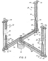
- Figure 5 is a fragmentary perspective view depicting the drive assembly of the Figure 1 sorting apparatus;
- Figure 6(a) is a schematic elevational view showing the sheets being loaded into one group of trays in the Figure 1 sorting apparatus;
- Figure 6(b) is a schematic elevational view showing one group of trays of the Figure 1 sorting apparatus after the sheets have been loaded therein;
- Figure 6(c) is a schematic elevational view illustrating one group of trays of the Figure 1 sorting apparatus being unloaded and the other group of trays being loaded; and
- Figure 6(d) is a schematic elevational view showing one group of trays of the Figure 1 sorting apparatus being unloaded and the other group of trays after the sheets have been loaded therein.
- As illustrated in Figure 1, the reproduction system, indicated generally by the
reference numeral 10, includes a copying machine, preferably an electrophotographic printing machine, designated generally by thereference numeral 12, and a sorting apparatus, indicated generally by thereference numeral 14.Electrophotographic printing machine 12 is capable of producing simplex or duplex copies at the option of the machine operator.Printing machine 12 has a platen for receiving documents to be reproduced and acontrol panel 18 for selecting different modes of operation such as simplex and duplex copying and the number of copies required to be reproduced. In accordance with the invention, theelectrophotographic printing machine 12 is coupled to sortingapparatus 14. Sortingapparatus 14 has two groups of sheet receiving members or trays. In operation, one group of trays, designated generally by thereference numeral 20, is in the sheet loading position while the other group of trays, designated generally by thereference numeral 22, is in the sheet unloading position. Preferably, each group of trays comprises ten trays. After the first group oftrays 22 has received copy sheets, the next group oftrays 20 is moved from the sheet unloading station to the sheet loading station. As the sheets are loaded into the second group oftrays 20, sheets are unloaded from the first group oftrays 22. The foregoing is shown more clearly in Figure 2. - Referring now to Figure 2, an operator is shown unloading sets of collated copies from the first group of
trays 22. This group oftrays 22 has advanced to the sheet unloading station. Simultaneously therewith, the second group oftrays 20 has advanced to the sheet loading position and copies are being advanced to the respective trays thereof. In unloading the collated sets of copies from the first group oftrays 22, the operator removes the collated sets from the front of the copy machine. Contrariwise, the sheets are loaded into the second group oftrays 20 from the side thereof. - Referring now to Figure 3, there is shown schematically the structure of
electrophotographic printing machine 12. Inasmuch as the art of electrophotographic printing is well known, the various processing stations employed in the printing machine are shown schematically and their operation briefly described with reference thereto. - As shown in Figure 3,
electrophotographic printing machine 12 includes adrum 24 having the outer periphery thereof coated with a suitable photoconductive material. Preferably, drum 24 is made from a conductive substrate, such as aluminum, having the photoconductive material, e.g. a selenium alloy, deposited thereon.Drum 24 rotates in the direction ofarrow 26 to pass through the various processing stations disposed thereabout. - Initially, drum 24 moves a portion of the photoconductive surface through charging
station 28. At chargingstation 28, a corona generating device charges the photoconductive surface ofdrum 24 to a relatively high, substantially uniform potential. A suitable corona generating device is described in U.S. Patent No. 2,836,725 issued to Vyverberg in 1958. - Thereafter, the charged portion of the photoconductive surface of
drum 24 is advanced throughexposure station 16. Atexposure station 16, an original document is positioned facedown on a transparent platen. The original document is scanned by a moving optical system so as to produce a flowing light image thereof. The optical system includes an elongated horizontally extendinglamp 30 and amovable lens 32. The lamp and lens move in coordination with one another across the platen to focus successive bands of illumination reflected from the original document onto the moving photoconductive surface ofdrum 24 in synchronism therewith. The optical light path is folded by means of a pair of image mirrors 34 and 36 interposed between the lens and photoconductive surface ofdrum 24. Under the influence of the flowing light image, the uniformly charged photoconductive surface is selectively discharged in the non-image area to record an electrostatic latent image ondrum 24. - Next, drum 24 advances the electrostatic latent image recorded on the photoconductive surface to
development station 38.Development station 38 includes a developer housing having a supply of developer material therein. Preferably, the developer material comprises carrier granules having toner particles adhering tribo-electrically thereto. Abucket conveyor 40 advances the developer material from the bottom ofdeveloper housing 38 to the top thereof. The material is then cascaded downwardly into the active development zone. As the developer material flows downwardly over the upwardly moving photoconductive surface ofdrum 24, the electrostatic latent image attracts the toner particles from the developer mix. This forms a toner powder image ondrum 24 corresponding to the informational areas of the original document being reproduced. -
Drum 24 then transports the toner powdef image developed on the photoconductive surface to transfer station 42. At transfer station 42, a sheet of support material is positioned in contact with the toner powder image deposited on the photoconductive surface ofdrum 24. The backside of the sheet of support material is sprayed with an ion discharge from a transfer corona generating device. This induces a charge on the sheet of support material having a polarity and.magnitude sufficient to attract the toner powder image from the photoconductive surface ofdrum 24 to the sheet of support material. - Invariably, after the sheet of support material is separated from the photoconductive surface of drum -24, some residual particles remain adhering thereto. These residual particles are removed from
drum 24 at cleaningstation 44. Preferably, cleaningstation 44 includes a cleaning corona generating device adapted to neutralize the electrostatic charge tending to hold the residual toner particles on the photoconductive surface ofdrum 24. The neutralized toner particles are then mechanically cleaned from the photoconductive surface by means of a brush or blade and the toner particles collected withinhousing 46. - After the sheet of support material has been removed from the photoconductive surface, a
transport 48 advances the sheet of support material, with the toner powder image thereon, to fusingstation 50. Fusingstation 50 includes a fuser assembly having aheated fuser roller 52 and a back-uproller 54.Fuser roll 52 and back-up roll 54 coact so as to support the advancing sheet of support material in pressure driving contact therebetween. The heated surface offuser roller 52 contacts the toner powder image on the surface of the sheet of support material. The pressure and heat permanently bond the toner particles to the sheet of support material in image configuration. - After leaving
fuser 50, the sheet of support material with the toner powder image permanently affixed thereto advances along curvilinear sheet guides, indicated generally by thereference numeral 56, which have a plurality of spaced rollers for advancing the sheet therealong.Guide 58 of sheet guides 56 is movable to advance the sheet of support material toconveyor 60 or to uppersheet supply tray 62.Tray 62 is arranged to recirculate the sheet of support material for duplex copying.Conveyor 60 advances the sheet of support material to sortingapparatus 14. - It is believed that the foregoing description is sufficient for purposes of the present invention to illustrate the general operation of an electrophotographic printing machine coupled to the sorting apparatus of the present invention.
- Sorting
apparatus 14 comprises a horizontal vacuum transport assembly which receives copy sheets fromconveyor 60 and advances them to a first group of sheet receiving members ortrays 20, or a second group of sheet receiving members ortrays 22. A drive system moves each group of tray assemblies vertically intermittently for receiving copy sheets along the transport path. Each group of trays includes approximately 10 trays. This facilitates multiple bin loading and unloading. Each tray includes atray portion 64 inclined at approximately 20° to the horizontal, and anend portion 66 which is substantially perpendicular totray portion 64 and then extends in a horizontal direction attail portion 68.Tray portion 64 andtail portion 68 are mounted oncam followers reference numeral 74. Each tray has three cam followers riding in the spiral grooves of three cam members. By this arrangement a three point suspension is provided for the tray assemblies. Each of thecam members 74 is divided into three independentlyrotatable portions Portion 76 may include a plurality of low pitch surfaces 82 whileportion 78 includes onehigh pitch surface 84 as well aslow pitch surface 82.High pitch surface 84 is located adjacent the sheet loading zone or station so as to open the spacing between trays facilitating the loading of sheets therein. After the sheet is received in the tray assembly, the tray assembly is then closed to the normal gap. - Referring now to Figure 5, the drive mechanism for moving the tray assemblies vertically will be described. The drive mechanism includes a
drive motor 86 which drives six timing belts, one for each portion ofcam member 74.Belts pulleys Pulley 94 is connected toshaft 100.Pulley 96 is connected toshaft 102 andpulley 98 is connected toshaft 104.Portion 80 of eachcam member 74 is hollow permittingshafts Shafts second portions 78 ofcam members 74. Thus, rotation ofmotor 86drives belts cause shafts middle portions 78 ofcam members 74.Clutch 106 couples motor 86 tobelts Belt 108 is entrained aboutpulley 114 onfirst portion 80 ofcam member 74.Belt member 112 is entrained aboutpulley 116 onfirst portion 80 ofcam member 74.Belt 110 is entrained aboutpulley 118 secured toportion 80 ofcam members 74.Gears respective portions 80 ofcam members 74.Gear 119 meshes withgear 124 onshaft 126.Shaft 126 has agear 128 on the end thereof opposed fromgear 124.Gear 128 meshes with thegear 130 onportion 76 ofcam member 74. In this manner, energization of clutch 106 couples motor 86 to belt 108.Belt 108 rotatesportion 80 ofcam member 74 andgear 119 thereon.Gear 119 rotatesgear 124 which, in turn, drivesshaft 126 andgear 128. Rotation ofgear 128 drivesgear 130 and rotatesportion 76 ofcam member 74. Thus, it is seen thatportions cam member 74 rotate simultaneously with energization ofclutch 106.Gear 122 meshes withgear 134 onshaft 136.Shaft 136 has agear 138 on the end thereof opposed fromgear 134.Gear 138 meshes withgear 140 onportion 76 ofcam member 74. Thus, energization of clutch 106 couples drivemotor 86 to belt 110.Belt 110 rotatesportion 80 ofcam member 74. Asportion 80 rotates,gear 122 rotates therewith drivinggear 134 andshaft 136. This, in turn, drivesgear 138 which causesgear 140 to rotate. Asgear 140 rotates,portion 76 ofcam member 74 rotates therewith. Hence, actuation ofclutch 106 causes drivemotor 86 to rotate bothportions cam member 74 simultaneously. Similarly,belt 112 rotatesportion 80 ofcam member 74.Gear 120 onportion 80 meshes withgear 142 onshaft 144.Shaft 144 has agear 146 on the end thereof opposed fromgear 142.Gear 146 meshes withgear 148 onportion 76 ofcam member 74. Hence, rotation ofgear 146 drives gear 148 which, in turn, drivesportion 76 ofcam member 74. It is, therefore, apparent that energization ofclutch 106 also couplesmotor 86 to belt 112 which drivesportion cam member 74 simultaneously. - Referring now to Figures 6(a) through 6(d), there is shown the manner of operation of sorting
apparatus 14. As depicted in Figure 6(a), the copy sheet advances in the direction ofarrow 150. With regard to Figure 6(a),clutch 106 is de-energized andportions cam members 74 are non-rotating. Thus, the first group oftrays 20 remains stationary. However,portion 78 ofcam member 74 is rotating. This drives the second group oftrays 22 in an upwardly direction, as indicated byarrow 152. As each tray ofgroup 22 passes the sheet path, indicated byarrow 150, a sheet is loaded therein. Thus, it is seen that the second group oftrays 22 moves in an upwardly direction in the loading station to receive copy sheets therein. After the last tray has received a copy sheet, control logic reverses the direction ofmotor 86 andclutch 106 is energized. - As shown in Figure 6(b), this drives
tray groups arrow 154. When the first tray ofgroup 20 passes the sheet receiving position, as indicated byarrow 150, the machine logic once again reverses the direction of rotation ofmotor 86 and de-energizes the clutch 106. At this time, the groups of trays are positioned as shown in Figure 6(c). - Turning now to Figure 6(c), only
portion 78 will rotate driving the first group oftrays 20 in the direction ofarrow 156 while the second group oftrays 22 having the copy sheets therein remains stationary. This permits the machine operator to remove the copy sheets from the second group oftrays 22 as copy sheets are being loaded into the first group oftrays 20. - Turning now to Figure 6(d),
group 20 is depicted with the last tray thereof having received a copy sheet. At this time, the machine logic actuates clutch 106 andportions cam member 74 rotate driving bothtray groups arrow 158. The first group oftrays 20 return to the unloading position, as shown in Figure 6(a), and the second group oftrays 22 moves to the loading position. It is thus seen that each group of trays has its own dedicated unloading station while using a common sheet loading station. Moreover, sheets are unloaded from one group of trays as they are being loaded into the other group of trays. In this manner, the sorting apparatus is limitless in capacity and operates in a rapid and efficient manner. - In recapitulation, it is evident that the sorting apparatus of the present invention comprises two groups of trays. One group of trays is receiving sheets at the common loading station with the other group of trays having sheets unloaded therefrom at a dedicated unloading station. After loading and unloading the sheets in the respective groups of trays, the process is reversed. Thus, the sorting apparatus of the present invention is limitless in capacity so as to readily enable an operator to perform an additional operation, i.e. stapling or stitching the collated sets of copies, simultaneously with new sets of copies being loaded into the various trays of the sorting apparatus.
Claims (6)
Applications Claiming Priority (2)
| Application Number | Priority Date | Filing Date | Title |
|---|---|---|---|
| US3441 | 1979-01-15 | ||
| US06/003,441 US4214746A (en) | 1979-01-15 | 1979-01-15 | Sorting apparatus |
Publications (2)
| Publication Number | Publication Date |
|---|---|
| EP0013632A1 EP0013632A1 (en) | 1980-07-23 |
| EP0013632B1 true EP0013632B1 (en) | 1983-07-20 |
Family
ID=21705891
Family Applications (1)
| Application Number | Title | Priority Date | Filing Date |
|---|---|---|---|
| EP80300130A Expired EP0013632B1 (en) | 1979-01-15 | 1980-01-15 | Sorting apparatus for sorting sheets |
Country Status (5)
| Country | Link |
|---|---|
| US (1) | US4214746A (en) |
| EP (1) | EP0013632B1 (en) |
| JP (1) | JPS5598053A (en) |
| CA (1) | CA1136081A (en) |
| DE (1) | DE3064170D1 (en) |
Families Citing this family (12)
| Publication number | Priority date | Publication date | Assignee | Title |
|---|---|---|---|---|
| GB2134493B (en) * | 1980-02-22 | 1985-02-20 | Docutel Corp | Currency note storing and despensing system |
| US4337936A (en) * | 1980-05-07 | 1982-07-06 | Gradco/Dendoki, Inc. | Compact sorter |
| US4911424A (en) * | 1983-04-13 | 1990-03-27 | Gradco Systems, Inc. | Sheet sorting machine |
| DE3774929D1 (en) * | 1986-05-17 | 1992-01-16 | Hasler Gmbh | DEVICE FOR STORING AND DISPENSING THICKNESS, AREA-LIKE OBJECTS. |
| JP2647093B2 (en) * | 1987-07-08 | 1997-08-27 | キヤノン株式会社 | Sheet sorter |
| JP2735247B2 (en) * | 1988-07-29 | 1998-04-02 | 株式会社リコー | Sheet handling device with post-processing function |
| JPH089453B2 (en) * | 1989-10-18 | 1996-01-31 | キヤノン株式会社 | Sheet sorter |
| JP3143231B2 (en) * | 1991-12-26 | 2001-03-07 | 株式会社リコー | Sheet sorting device |
| JP3247546B2 (en) * | 1994-06-03 | 2002-01-15 | ニスカ株式会社 | Sorter |
| KR0139041B1 (en) * | 1995-01-12 | 1998-06-15 | 우석형 | Copier sorter, discharge sorting device, stapling device and stapling sorter using them |
| US6227539B1 (en) * | 1998-10-21 | 2001-05-08 | Xerox Corporation | Printer mailboxing system with automatic variable capacity bins |
| JP6452307B2 (en) * | 2014-04-14 | 2019-01-16 | キヤノン株式会社 | Sheet storage device and image forming apparatus |
Family Cites Families (9)
| Publication number | Priority date | Publication date | Assignee | Title |
|---|---|---|---|---|
| US3131819A (en) * | 1961-04-14 | 1964-05-05 | Clark Aiken Company | Shuttle piler |
| US3273882A (en) * | 1963-05-23 | 1966-09-20 | Norfin | Sheet collating device |
| US3395913A (en) * | 1966-10-11 | 1968-08-06 | Xerox Corp | Sheet material distribution system |
| US3516654A (en) * | 1968-04-18 | 1970-06-23 | Luis Mestre | Sheet sorter having automatic sheet feed control and restart |
| US3561753A (en) * | 1968-07-29 | 1971-02-09 | Norfin | Sheet collating device |
| LU59256A1 (en) * | 1969-08-08 | 1971-06-21 | Ordibel Sprl | |
| US3848867A (en) * | 1972-09-20 | 1974-11-19 | Norfin | No-counter sorter-stacker |
| US3788640A (en) * | 1972-12-29 | 1974-01-29 | Xerox Corp | Moving bin sorting apparatus |
| US3995748A (en) * | 1975-07-21 | 1976-12-07 | Xerox Corporation | Sorter apparatus |
-
1979
- 1979-01-15 US US06/003,441 patent/US4214746A/en not_active Expired - Lifetime
- 1979-11-13 CA CA000339751A patent/CA1136081A/en not_active Expired
- 1979-11-29 JP JP15495179A patent/JPS5598053A/en active Granted
-
1980
- 1980-01-15 EP EP80300130A patent/EP0013632B1/en not_active Expired
- 1980-01-15 DE DE8080300130T patent/DE3064170D1/en not_active Expired
Also Published As
| Publication number | Publication date |
|---|---|
| US4214746A (en) | 1980-07-29 |
| EP0013632A1 (en) | 1980-07-23 |
| JPS5598053A (en) | 1980-07-25 |
| JPS6332701B2 (en) | 1988-07-01 |
| CA1136081A (en) | 1982-11-23 |
| DE3064170D1 (en) | 1983-08-25 |
Similar Documents
| Publication | Publication Date | Title |
|---|---|---|
| CA1127589A (en) | Sorting apparatus for collating simplex and duplex copies | |
| US3719266A (en) | Sheet stacking apparatus | |
| US3848868A (en) | Sheet sorting apparatus | |
| US3788640A (en) | Moving bin sorting apparatus | |
| US4681310A (en) | Sorting apparatus | |
| CA1115330A (en) | Duplex system and method for pre-collation copiers | |
| US3866904A (en) | Multiple feed sorting apparatus | |
| US3697050A (en) | Cross-mixing baffle | |
| JPH04226253A (en) | Positioning control device for elevating machine tray | |
| JPH0521229B2 (en) | ||
| US4214746A (en) | Sorting apparatus | |
| US4368973A (en) | Recirculating document feeder | |
| US4365889A (en) | Document handling unit | |
| US3868019A (en) | Tray apparatus | |
| GB2024083A (en) | Clinching staples | |
| JPS5825628B2 (en) | Single-sided and double-sided copying equipment | |
| US3973769A (en) | Compact sorting apparatus | |
| GB2219990A (en) | Sheet stacking and inverting | |
| US3908978A (en) | Binless sorting apparatus | |
| US4133522A (en) | Pivoting tray sorting apparatus | |
| JPH0217460B2 (en) | ||
| US5105231A (en) | Image formation apparatus having means for reversing the order of stacking of image bearing documents | |
| US4220325A (en) | Sorting apparatus | |
| EP0333258B1 (en) | Method of and copying machine for copying originals in order on both sides of receiving sheets | |
| US3998450A (en) | Sorting apparatus |
Legal Events
| Date | Code | Title | Description |
|---|---|---|---|
| PUAI | Public reference made under article 153(3) epc to a published international application that has entered the european phase |
Free format text: ORIGINAL CODE: 0009012 |
|
| AK | Designated contracting states |
Designated state(s): DE FR GB |
|
| 17P | Request for examination filed |
Effective date: 19801117 |
|
| GRAA | (expected) grant |
Free format text: ORIGINAL CODE: 0009210 |
|
| AK | Designated contracting states |
Designated state(s): DE FR GB |
|
| REF | Corresponds to: |
Ref document number: 3064170 Country of ref document: DE Date of ref document: 19830825 |
|
| ET | Fr: translation filed | ||
| PLBE | No opposition filed within time limit |
Free format text: ORIGINAL CODE: 0009261 |
|
| STAA | Information on the status of an ep patent application or granted ep patent |
Free format text: STATUS: NO OPPOSITION FILED WITHIN TIME LIMIT |
|
| 26N | No opposition filed | ||
| PGFP | Annual fee paid to national office [announced via postgrant information from national office to epo] |
Ref country code: DE Payment date: 19850122 Year of fee payment: 6 |
|
| PG25 | Lapsed in a contracting state [announced via postgrant information from national office to epo] |
Ref country code: GB Effective date: 19890115 |
|
| PGFP | Annual fee paid to national office [announced via postgrant information from national office to epo] |
Ref country code: FR Payment date: 19890131 Year of fee payment: 10 |
|
| GBPC | Gb: european patent ceased through non-payment of renewal fee | ||
| PG25 | Lapsed in a contracting state [announced via postgrant information from national office to epo] |
Ref country code: DE Effective date: 19891003 |
|
| PG25 | Lapsed in a contracting state [announced via postgrant information from national office to epo] |
Ref country code: FR Effective date: 19900928 |
|
| REG | Reference to a national code |
Ref country code: FR Ref legal event code: ST |