EP0013544A1 - Threaded sleeve coupling having valves with an adjustable aperture - Google Patents
Threaded sleeve coupling having valves with an adjustable aperture Download PDFInfo
- Publication number
- EP0013544A1 EP0013544A1 EP79830051A EP79830051A EP0013544A1 EP 0013544 A1 EP0013544 A1 EP 0013544A1 EP 79830051 A EP79830051 A EP 79830051A EP 79830051 A EP79830051 A EP 79830051A EP 0013544 A1 EP0013544 A1 EP 0013544A1
- Authority
- EP
- European Patent Office
- Prior art keywords
- joint
- shoulder
- male
- cylindrical
- joints
- Prior art date
- Legal status (The legal status is an assumption and is not a legal conclusion. Google has not performed a legal analysis and makes no representation as to the accuracy of the status listed.)
- Withdrawn
Links
Images
Classifications
-
- F—MECHANICAL ENGINEERING; LIGHTING; HEATING; WEAPONS; BLASTING
- F16—ENGINEERING ELEMENTS AND UNITS; GENERAL MEASURES FOR PRODUCING AND MAINTAINING EFFECTIVE FUNCTIONING OF MACHINES OR INSTALLATIONS; THERMAL INSULATION IN GENERAL
- F16L—PIPES; JOINTS OR FITTINGS FOR PIPES; SUPPORTS FOR PIPES, CABLES OR PROTECTIVE TUBING; MEANS FOR THERMAL INSULATION IN GENERAL
- F16L29/00—Joints with fluid cut-off means
- F16L29/04—Joints with fluid cut-off means with a cut-off device in each of the two pipe ends, the cut-off devices being automatically opened when the coupling is applied
Definitions
- the invention relates to a rapid screw joint for pipes, adjustable in the opening, particularly but not necessarily, used for the transmission of fluids and especially for the transmission of pressurized fluids and in particular hydraulic oil, for joining hydraulic pipes. in the control of hydraulic oil pressure devices.
- a particular use of said rapid screw joints is that of joining hydraulic transmission pipes for the operation of devices or machines accessory to a main machine, such as connection or connection: to a pressure source such as an oil pump hydraulic supply, to a tank, to a device for controlling the pressure of the oil, etc., thus allowing the disjunction or separation of the said pipes even if they remain under pressure.
- a pressure source such as an oil pump hydraulic supply
- a tank to a device for controlling the pressure of the oil, etc.
- the object of the present invention is to provide a remedy for the stated drawbacks and in particular to make possible a rapid joining and disjunction of the connecting pipes in tre.a main machine and a machien or auxiliary device controlled by the first even if the said hoses are under pressure, preserving them from the loss of oil and ensuring in the separate half-joints the tightness and cela constituting the two traditional valves, and eliminating the purge valve and that of the check valve; providing, in addition, a structure such that it can withstand greater pressure in the joint compared to known types of joints, ensuring a much safer junction with greater clamping efficiency while preventing the half-joints from sticking out.
- the rapid joint consists of two half joints which are characterized by a female body and a male body respectively screwable together, axially hollow, having the shape of tubes with in the respective ends an external key socket, and an internal thread for screwing to the end d '' a pipe being foreseen in the hollow not threaded part of each body, the installation of an interchangeable check valve pressed by a spring against a shoulder towards the opening in the direction of junction and being provided in the head te of said valve a toroidal rubber ring seal tightly closed in the valve, forming a seat against the said shoulder of the body which is conical and where each valve head in the sealing position projects outwards so that by screwing the two half joints the heads of the respective valves will touch each other pushing against each other and progressively moving against the respective spring to open the passage of the fizid in the interior of the two half joints and yet in the two respective lines of pipe thus joined.
- each said valve has a posterior tail for collecting the end of said spring, which has holes for making a passage of said fluid from the opening of the seat of the valve head. to reach the inside of the spring and then into the pipe and vice versa.
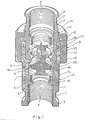
- FIG. 1 represents a view in axial section in perspective of the joint produced in accordance with the present invention in which the two half-joints are screwed together, without illustrating the screwing to pipes of the known type;
- 2 shows a side view of the quick joint in reduced scale with reference to fig.1 where the two half-joints respectively male and female are detached;
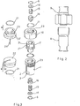
- FIG. 3 represents an exploded per spective view with axial development of the joint, following the preceding figures;
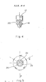
- FIG. 4 represents a view of the sealing / opening and flow adjustment valve, installed inside each male and female body of the two half-joints in axial section A-A as shown in FIG. 5;
- Figure 5 shows a plan view of said valve illustrated in fig.4.
- the seal is constituted by a half male joint "A” and a female half joint "B".
- the male half-joint "A” comprises a hollow cylindrical body with tube 1 with a key socket 2 and end edge 3.
- the female half-joint "B" likewise comprises a hollow cylindrical body with tube 1 'with a key socket 2' ed a terminal edge 3 '.
- Either the body 1 of the male half joint "A” that the body 1 'of the female half joint “B” are in the internal hole structured identically and precisely this hole comprises: an internal end thread 4 for the respective screws sow the end of a pipe; an annular groove 5 for a retaining ring 6, a through hole 7, a slight widening 8 and a conically shaped shoulder 9 for the purposes which will be explained below.
- the female half-joint "B” freely supports a coupling nut 10 which is axially blocked by a stop ring 11 which is housed in an annular groove made in the body 1 '.
- the tube body 1 ′ of the female half joint has a cylindrical external shape 12 constituting a male part which couples with a female part 12 practical in the tube body 1 of the male half joint, terminating on the shoulder 13 which delimits on the two said cone shoulder 9 in opposition.
- the valve 16 has a conformation of a head with an annular seal 18, which under the action of the spring 15 will beat against the said conical shoulder 9 to achieve a tight hold of the pipe screwed in 4, when each half joint is unscrewed.
- the two opposite external parts 19 of the two heads of the valves 16 repel according to the screwing of the nut 10 by determining a more or less marked opening for the passage of the fluid by the remoteness of the gasket 18 of the conical seat shoulder 9.
- the gasket 18 is tightly closed in the head of said valve 16 so that it cannot come out and this to prevent its displacement and ensure the water tightness of the attached.
- Said valve has in addition posteriorly a cylindrical casing form 21 for the end of the spring 15 and in the head of the cylindrical casing are made three holes 20 which allow the passage of the fluid through the half joint and between the spring 15 , which allows a passage of the oil without obstacles directly in the pipe.
- each male and female half joint using an elastic ring 21 links by a chain 24 a respective female 22 and male 22 'screw cap to be screwed to the respective 2.3 male thread of the body of the half-seal (A) and female of the nut 10 of the half-seal (B) provided that each elastic ring 21 is housed in the respective groove 25 of each half-seal.
Abstract
Description
L'invention concerne un joint rapid à vis pour tuyaux, réglable dans l'ouverture, particulièrement mais pas ne cessairement, utilisé pour la transmission de fluides et spécialement pour la transmission de fluides sous pression et en particulier huile hydraulique, pour joindre des tuyaux hydrauliques dans le command de di spositifs hydrauliques à huile sous pression.The invention relates to a rapid screw joint for pipes, adjustable in the opening, particularly but not necessarily, used for the transmission of fluids and especially for the transmission of pressurized fluids and in particular hydraulic oil, for joining hydraulic pipes. in the control of hydraulic oil pressure devices.
L'utilisation de ce joint rapid et celle de joindre des tuyaux ou tubes flexibles entre eux, pour transmissions hydrauliques à huile sous pression.The use of this rapid joint and that of joining flexible pipes or tubes together for hydraulic pressurized oil transmissions.
Une particulière utilisation des dits joints rapids à vis est celle de joindre des tuyaux de transmission hydraulique pour le fonctionnement de dispositifs ou machines accessoi res d'une machine principale, comme la connexion ou jon ction: au une source de pression teleque une pompe à huile hydraulique d'alimentation, à un réservoir, à un dispositif de contrôle de la pression de l'huile etc., permettant aus si la disjonction ou séparation des dits tuyaux même s'ils restent sous pression.A particular use of said rapid screw joints is that of joining hydraulic transmission pipes for the operation of devices or machines accessory to a main machine, such as connection or connection: to a pressure source such as an oil pump hydraulic supply, to a tank, to a device for controlling the pressure of the oil, etc., thus allowing the disjunction or separation of the said pipes even if they remain under pressure.
Dans l'état actuel de la techinque, on relève plusieurs inconvenients dans les acutels joints rapids à vis et en particulier on rescontre: l'absence de rapidité dans l'opé ration de jonction et disjonction; l'absence d'une tenue étanche dans cette opération, ce qui comporte l'utilisation de deux soupapes traditionelles avec l'emploi d'une soupape de purge ou vanne de décharge et soupape de retenue. On connait déja des joints à contre-pression de ressort qui éliminent une partie des inconvenients énoncés, mais ceux-ci ont l'inconvénient de ne permettre pas un régulier et large flux des fluides, ils sont enoutre pas résistants, de fon ctbmement limitée et ne sont pas réalisés de manière de permettre l'interchangeableté des pièces qui sont particuliè rement soumis à usure ou à défauts de fonctionnement obli geant l'utilisateur à changer le joint complet.In the current state of the art, there are several drawbacks in the current rapid screw joints and in particular we encounter: the lack of speed in the junction and disjunction operation; the absence of a tight seal in this operation, which involves the use of two traditional valves with the use of a purge valve or relief valve and check valve. There are already known spring pressure seals which eliminate some of the drawbacks stated, but these have the disadvantage of not allowing a regular and wide flow of fluids, they are also not resistant, fundamentally limited and are not made so as to allow the interchangeability of the parts which are particularly subject to wear or malfunctions forcing the user to change the complete seal.
La présente invention a pour but d'apporter un remède aux incovénients énoncés et en particulier de rendre possible une jonction et disjonction rapide des tuyaux de liason en tre.une machine principale et une machien ou dispositif au xiliaire commandé par la première même si les dits tuyaux sont sous pression, les preservant de la perte d'huile et en assûrant dans les demijoints séparés l'étanchéité et céla sobstituant les deux soupapes traditionelles, et éliminant la soupape de purge et celle de retenue; prévoiant enoutre une structure telle qui puisse supporter dans le joint une pression supérieure par rapport aux types de joints connus en assûrant une jonction bien plus sûre avec une plus gran de efficacité de serrage tout en empêchant qui les demijoints detaches se saillent.The object of the present invention is to provide a remedy for the stated drawbacks and in particular to make possible a rapid joining and disjunction of the connecting pipes in tre.a main machine and a machien or auxiliary device controlled by the first even if the said hoses are under pressure, preserving them from the loss of oil and ensuring in the separate half-joints the tightness and cela constituting the two traditional valves, and eliminating the purge valve and that of the check valve; providing, in addition, a structure such that it can withstand greater pressure in the joint compared to known types of joints, ensuring a much safer junction with greater clamping efficiency while preventing the half-joints from sticking out.
Suivant l'innovation le joint rapid est constitué par deux demijoints qui sont caractérisés par un corps femelle et un corps mâle respectivement vissables entre eux, creux axia lement, ayant une forme de tubes avec dans les extrémités respectives une prise de clé extérieure, et un filetage in térieur pour se visser à l'extrémité d'un tuyau étant pré vu dans la partie creuse pas filété de chaque corps, l'in stallation d'une soupape de retenue interchangeable pressée par un ressort contre un épaulement vers l'ouverture dans la direction de jonction et étant prévu enoutre dans la tê te de la dite soupape une garniture anulaire toroidal en caoutchouc bien fermée dans la soupape,faisant siège d'étan cheité contre le dit épaulement du corps qui est conique et où chaque tête de soupape en position d'étancheité fait saillie au déhors de manière que en vissant les deux demi joints les têtes des soupapes respectives vont se toucher se repoussant l'une.contre l'autre et se déplaçant progres sivement contre le ressort respectif pour ouvrir le passage du fluid dans l'intérieur des deux demijoints et pourtant dans les deux traits de tuyaux respectifs ainsi joints.Following the innovation, the rapid joint consists of two half joints which are characterized by a female body and a male body respectively screwable together, axially hollow, having the shape of tubes with in the respective ends an external key socket, and an internal thread for screwing to the end d '' a pipe being foreseen in the hollow not threaded part of each body, the installation of an interchangeable check valve pressed by a spring against a shoulder towards the opening in the direction of junction and being provided in the head te of said valve a toroidal rubber ring seal tightly closed in the valve, forming a seat against the said shoulder of the body which is conical and where each valve head in the sealing position projects outwards so that by screwing the two half joints the heads of the respective valves will touch each other pushing against each other and progressively moving against the respective spring to open the passage of the f luid in the interior of the two half joints and yet in the two respective lines of pipe thus joined.
Une ultérieure caractéristique concerne le fait que chaque dite soupape présente une queue postérieure d'encaissement de l'extremité du dit ressort, laquelle comporte des trous pour réaliser un passage du dit fluide à partir de l'ouver ture du siège de la tête de soupape pour arriver dans l'in térieur du ressort et après dans le tuyau et vice-versa.A further characteristic relates to the fact that each said valve has a posterior tail for collecting the end of said spring, which has holes for making a passage of said fluid from the opening of the seat of the valve head. to reach the inside of the spring and then into the pipe and vice versa.
Les caracttéristiques enoncées séront en tout cas mieux comprises et évidencés et d'autres paraîtront dans la sui vante description plus en détail à l'aide de dessins repré sentant seulement un mode d'exécution.The characteristics stated will in any case be better understood and evident and others will appear in the following description in more detail with the aid of drawings representing only one embodiment.
La figure 1 représente une vue en section axial en perspective du joint réalisé conformément à la presen te invention où les deux demijoints sont vissés entre eux, sans illustrer le vissement aux tuyaux du type connu; la figure 2 représente une vue de côté du joint rapide en echelle réduite se référant à la fig.1 où les deux demijoints respectivement mâle et femelle sont détachés; la figure 3 représente une vue en per spective explosée à développement axial du joint, sui vant les figures précédentes; la figure 4 représente une vue de la soupape d'étancheité/ouverture et regla ge du flux,installée à l'intérieur de chaque corps mâle et femelle des deux demijoints en section axial A-A comme indiqué dans la figure 5; la figure 5 repré sente une vue de plan de la dite soupape illustrée dans la fig.4.FIG. 1 represents a view in axial section in perspective of the joint produced in accordance with the present invention in which the two half-joints are screwed together, without illustrating the screwing to pipes of the known type; 2 shows a side view of the quick joint in reduced scale with reference to fig.1 where the two half-joints respectively male and female are detached; FIG. 3 represents an exploded per spective view with axial development of the joint, following the preceding figures; FIG. 4 represents a view of the sealing / opening and flow adjustment valve, installed inside each male and female body of the two half-joints in axial section A-A as shown in FIG. 5; Figure 5 shows a plan view of said valve illustrated in fig.4.
Comme on peut relever dans le figures et en particulier dans les figures 1,2,3 le joint est constitué par un demi joint mâle "A" et un demijoint femelle "B".As can be seen in the figures and in particular in Figures 1,2,3 the seal is constituted by a half male joint "A" and a female half joint "B".
Le demijoint mâle "A" comprend un corps cylindrique creux à tube 1 avec une prise de clé 2 et bord terminal 3. Le demijoint femelle "B". comprend de même un corps cylindrique creux à tube 1' avec une prise de clé 2' ed un bord termi nal 3'.The male half-joint "A" comprises a hollow cylindrical body with
Soit le corps 1 du demijoint mâle "A" que le corps 1' du demijoint femelle "B" sont dans le trou intérieur structu rés en manière identique et précisement ce trou comprend: un filetage d'extrémité intérieur 4 pour le respectif vis sèment à l'extrémité d'un tuyau; une rainure annulaire 5 pour une bague de retenue 6, un trou de passage 7, un légèr élargissement 8 et un épaulement à forme conique 9 pour les buts qui séront expliqués ci-aprés.Either the
Le demijoint femelle "B" supporte rotativement libre un écrou de raccord 10 lequel est bloqué axialement par une bague d'arrêt 11 qui est logée dans une rainure annulai re pratiquée dans le corps 1'.The female half-joint "B" freely supports a
Soit l'extremité extérieure du corps creux (1) du demijoint mâle "A" que l'extremité intérieure de l'écrou 10 sur le dit demijoint creux "B", sont filétés pour se visser entre eux en serrage contre l'épaulement 26 comme indiqué en fig.1.Either the outer end of the hollow body (1) of the male half-joint "A" and the inner end of the
Le corps à tube 1' du demijoint femelle comporte une forme extérieure cylindrique 12 constituant une partie mâle qui s'accouple avec une partie femelle 12 pratique dans le corps à tube 1 du demijoint mâle, terminant sur l'épaule ment 13 qui délimite sur les deux le dit épaulement coni que 9 en opposition.The
Dans l'intérieur des deux corps à tube 1.,1' se trouvent bloqués par la bague de retenue 6, respectivement une ba gue d'arrêt 14, un ressort de compression 15 et une soupa pe 16.In the interior of the two
Sur une des parois cylindriques 12 des corps 1,1' est pré vue une rainure anulaire pour l'insertion d'une garniture annulaire d'étancheité 17 entre les deux corps.On one of the
La soupape 16 présente une conformation d'une tête avec une garniture annulaire d'étancheité 18, laquelle sous l'action du ressort 15 va battre contre le dit épaulement conique 9 pour réaliser une tenue étanche du tuyau vissé en 4, lorsque chaque demijoint est devissé.The
La partie extérieure 19.de la tête de la dite soupape 16 poussée par le ressort 15jse penché au dehors du contre épaulement (13) lorsque la garniture annulaire d'étanchei té va battre contre l'épaulement conique 9.The
Si les deux demijoints viennent vissés entre eux les deux parties extérieures 19 opposées des deux têtes des soupapes 16 se repoussent en fonction du visse ment de l'écrou 10 en déterminant une ouverture plus ou moins marquée pour le passage du fluide par l'éloignement de la garniture 18 de l'épaulement conique de siège 9. La garniture d'étancheité 18 est bien fermé dans la tête de la dite soupape 16 de manière qu'elle ne puisse pas sor tir et cela pour empêcher son déplacement et assurer là étancheité du joint.If the two half-joints are screwed together, the two opposite
La dite soupape présente enoutre postérieurement une for me de encaissement cylindrique 21 pour l'extrémité du ressort 15 et dans la tête de l'encaissement cylindrique sont pra tiqués trois trous 20 qui permettent le passage du fluide à travers le demijoint et entre le ressort 15,ce qui per met un passage de l'huile sans obstacles directement dans le tuyau.Said valve has in addition posteriorly a
Le bord 3 empêche à la clé de glisser au dehors de la prise de clé 2 pendant le vissage du demijoint au tuyau. Une ultérieure caractéristique concerne le fait que chaque demijoint mâle et femelle à l'aide d'une bague élastique 21 lie par une chaine 24 un respectiv bouchon à vis femelle 22 et mâle 22' pour se visser à le respectif filetage 2.3 mâlè du corps du demijoint (A) et femellede l'écrou 10 du demijoint (B) étant prévu que chaque bague élastique 21 se loge dans la rainure- respective 25 de chaque demijoint. Udine, le 29 Novembre 1979The
Claims (7)
Applications Claiming Priority (2)
| Application Number | Priority Date | Filing Date | Title |
|---|---|---|---|
| IT8352478 | 1978-12-19 | ||
| IT83524/78A IT1105688B (en) | 1978-12-19 | 1978-12-19 | QUICK COUPLING SCREW FOR PIPES, ADJUSTABLE IN OPENING |
Publications (1)
| Publication Number | Publication Date |
|---|---|
| EP0013544A1 true EP0013544A1 (en) | 1980-07-23 |
Family
ID=11322818
Family Applications (1)
| Application Number | Title | Priority Date | Filing Date |
|---|---|---|---|
| EP79830051A Withdrawn EP0013544A1 (en) | 1978-12-19 | 1979-12-11 | Threaded sleeve coupling having valves with an adjustable aperture |
Country Status (2)
| Country | Link |
|---|---|
| EP (1) | EP0013544A1 (en) |
| IT (1) | IT1105688B (en) |
Cited By (4)
| Publication number | Priority date | Publication date | Assignee | Title |
|---|---|---|---|---|
| EP1988321A1 (en) | 2007-05-04 | 2008-11-05 | Dall'Oglio, Stefano | Device for the interconnection of hydrauliccircuits in a mono-tube system for heat delivering with both steam and liquid circulation |
| CN104763853B (en) * | 2015-04-21 | 2016-08-17 | 中山市雅西环保科技有限公司 | Joint |
| CN105953003A (en) * | 2015-04-02 | 2016-09-21 | 中山市雅西环保科技有限公司 | Water pipe joint with pushing disc |
| AT18015U1 (en) * | 2019-12-13 | 2023-10-15 | Cold Solutions Vbb Kaeltetechnik Gmbh | Coupling for fluids |
Citations (5)
| Publication number | Priority date | Publication date | Assignee | Title |
|---|---|---|---|---|
| US2931668A (en) * | 1956-04-30 | 1960-04-05 | Bastian Blessing Co | Coupling |
| US3537478A (en) * | 1968-10-29 | 1970-11-03 | Aeroquip Corp | Quick acting fluid coupling |
| FR2033563A5 (en) * | 1969-02-27 | 1970-12-04 | Guiot & Cie Ets | |
| US4002186A (en) * | 1975-10-10 | 1977-01-11 | The United States Of America As Represented By The Secretary Of The Navy | Quick disconnect coupling |
| DE2642724A1 (en) * | 1976-09-23 | 1978-03-30 | Fischer Wolf E | Hydraulic pipe coupling connected under pressure - has load and supply end valves held together by hydraulic force |
-
1978
- 1978-12-19 IT IT83524/78A patent/IT1105688B/en active
-
1979
- 1979-12-11 EP EP79830051A patent/EP0013544A1/en not_active Withdrawn
Patent Citations (5)
| Publication number | Priority date | Publication date | Assignee | Title |
|---|---|---|---|---|
| US2931668A (en) * | 1956-04-30 | 1960-04-05 | Bastian Blessing Co | Coupling |
| US3537478A (en) * | 1968-10-29 | 1970-11-03 | Aeroquip Corp | Quick acting fluid coupling |
| FR2033563A5 (en) * | 1969-02-27 | 1970-12-04 | Guiot & Cie Ets | |
| US4002186A (en) * | 1975-10-10 | 1977-01-11 | The United States Of America As Represented By The Secretary Of The Navy | Quick disconnect coupling |
| DE2642724A1 (en) * | 1976-09-23 | 1978-03-30 | Fischer Wolf E | Hydraulic pipe coupling connected under pressure - has load and supply end valves held together by hydraulic force |
Cited By (5)
| Publication number | Priority date | Publication date | Assignee | Title |
|---|---|---|---|---|
| EP1988321A1 (en) | 2007-05-04 | 2008-11-05 | Dall'Oglio, Stefano | Device for the interconnection of hydrauliccircuits in a mono-tube system for heat delivering with both steam and liquid circulation |
| CN105953003A (en) * | 2015-04-02 | 2016-09-21 | 中山市雅西环保科技有限公司 | Water pipe joint with pushing disc |
| CN105953003B (en) * | 2015-04-02 | 2017-11-17 | 中山市雅西环保科技有限公司 | A kind of water pipe head with platen |
| CN104763853B (en) * | 2015-04-21 | 2016-08-17 | 中山市雅西环保科技有限公司 | Joint |
| AT18015U1 (en) * | 2019-12-13 | 2023-10-15 | Cold Solutions Vbb Kaeltetechnik Gmbh | Coupling for fluids |
Also Published As
| Publication number | Publication date |
|---|---|
| IT7883524A0 (en) | 1978-12-19 |
| IT1105688B (en) | 1985-11-04 |
Similar Documents
| Publication | Publication Date | Title |
|---|---|---|
| CA2754552C (en) | Connecting device with threaded lugs used as a locking device and connector including such a device | |
| JPS5949477B2 (en) | union fittings | |
| FR2582772A1 (en) | COUPLING FOR PIPES | |
| FR2487945A1 (en) | SEALING PRESS OR SEAL, IN SCRATCHED ELEMENTS THAT MAY BE PLACED LATERALLY, IN PARTICULAR ON A TUBE | |
| FR2663080A1 (en) | ASSEMBLY FORMING COUPLING CONNECTION FOR VEHICLE ENGINE REFRIGERANT CIRCUITS. | |
| EP1085245B1 (en) | Means for connecting a pipe to a tubular body | |
| EP0300023B1 (en) | Rapid assembly connector | |
| EP0740101B1 (en) | Quick acting coupling having an autonomously loaded valve | |
| EP0013544A1 (en) | Threaded sleeve coupling having valves with an adjustable aperture | |
| FR2855239A1 (en) | Hydraulic fluid pipe fitting, has joints provided between tubular and coupling parts to delimit chambers which are placed in communication during coupling phase, by groove when coupling part is in coupled or decoupled position | |
| FR2687757A1 (en) | INTERLOCKING COUPLING FOR CONNECTING DUCTS CONDUCTED BY A FLUID. | |
| CH442899A (en) | Quick joint device for flexible plastic tubes | |
| EP0521800B1 (en) | Quick-acting coupling of a pneumatic circuit under pressure with a device | |
| FR2906341A3 (en) | Water pocket connecting assembly, has valves pushed one another to open respective holes so that passages communicate with each other when reception and insertion parts are connected, where valves hermetically seal respective holes | |
| LU86302A1 (en) | PARTICULAR TAP STRUCTURE FOR LIQUEFIED GAS BOTTLES | |
| FR2889796A1 (en) | Cosmetic pen, has cap with pressure surface extending inwards from cap`s inner periphery so as to press flange of piston piece against sleeve and to push tubular part in order to seal holes of sleeve in air-tight manner | |
| EP0976419A1 (en) | Connecting device for peritoneal dialysis line | |
| EP0180503B1 (en) | Quick-release coupling for pipes under fluid pressure and use of such a coupling in the filling of a container | |
| FR3072154A1 (en) | CONNECTION ASSEMBLY FOR FLUID TRANSPORT CONDUITS | |
| FR2527741A1 (en) | Quick-release connector for pipework - has delayed unlocking operation ensuring decompression and avoiding rapid separation | |
| FR2520478A1 (en) | SELF-CLOSING COUPLER, PARTICULARLY FOR FLUID OR REFRIGERANT | |
| EP0441686A1 (en) | Sealed connection device for two identical pipes | |
| FR2522385A1 (en) | Spherical plug valve - has purge orifice in plug with discharge port and O=ring seals | |
| BE882384A (en) | FLEXIBLE CONNECTION HOSE FOR TAPS PROVIDED WITH A SHUT-OFF VALVE WITH A SPHERICAL SHUTTER | |
| JP2005024085A (en) | Pipe joint |
Legal Events
| Date | Code | Title | Description |
|---|---|---|---|
| PUAI | Public reference made under article 153(3) epc to a published international application that has entered the european phase |
Free format text: ORIGINAL CODE: 0009012 |
|
| AK | Designated contracting states |
Designated state(s): AT BE CH DE FR GB LU NL SE |
|
| 17P | Request for examination filed |
Effective date: 19801230 |
|
| STAA | Information on the status of an ep patent application or granted ep patent |
Free format text: STATUS: THE APPLICATION IS DEEMED TO BE WITHDRAWN |
|
| 18D | Application deemed to be withdrawn |
Effective date: 19820630 |
|
| RIN1 | Information on inventor provided before grant (corrected) |
Inventor name: PIGNAT, CARLO Inventor name: PIGNAT, GINO DI CARLO Inventor name: PIGNAT, IVO Inventor name: PIGNAT, GINO |