EP0013140B1 - Fuel injection pump - Google Patents
Fuel injection pump Download PDFInfo
- Publication number
- EP0013140B1 EP0013140B1 EP79302983A EP79302983A EP0013140B1 EP 0013140 B1 EP0013140 B1 EP 0013140B1 EP 79302983 A EP79302983 A EP 79302983A EP 79302983 A EP79302983 A EP 79302983A EP 0013140 B1 EP0013140 B1 EP 0013140B1
- Authority
- EP
- European Patent Office
- Prior art keywords
- plunger
- fuel
- chamber
- pump
- bore
- Prior art date
- Legal status (The legal status is an assumption and is not a legal conclusion. Google has not performed a legal analysis and makes no representation as to the accuracy of the status listed.)
- Expired
Links
- 239000000446 fuel Substances 0.000 title claims description 142
- 238000002347 injection Methods 0.000 title claims description 58
- 239000007924 injection Substances 0.000 title claims description 58
- 238000005086 pumping Methods 0.000 claims description 47
- 239000012530 fluid Substances 0.000 claims description 6
- 239000010763 heavy fuel oil Substances 0.000 claims description 2
- 125000006850 spacer group Chemical group 0.000 description 14
- 238000004891 communication Methods 0.000 description 9
- 230000003628 erosive effect Effects 0.000 description 7
- 230000008030 elimination Effects 0.000 description 4
- 238000003379 elimination reaction Methods 0.000 description 4
- 238000002485 combustion reaction Methods 0.000 description 3
- 230000006835 compression Effects 0.000 description 3
- 238000007906 compression Methods 0.000 description 3
- 238000007789 sealing Methods 0.000 description 3
- 238000011161 development Methods 0.000 description 2
- 239000007921 spray Substances 0.000 description 2
- BYHQTRFJOGIQAO-GOSISDBHSA-N 3-(4-bromophenyl)-8-[(2R)-2-hydroxypropyl]-1-[(3-methoxyphenyl)methyl]-1,3,8-triazaspiro[4.5]decan-2-one Chemical compound C[C@H](CN1CCC2(CC1)CN(C(=O)N2CC3=CC(=CC=C3)OC)C4=CC=C(C=C4)Br)O BYHQTRFJOGIQAO-GOSISDBHSA-N 0.000 description 1
- 230000000712 assembly Effects 0.000 description 1
- 238000000429 assembly Methods 0.000 description 1
- 238000010276 construction Methods 0.000 description 1
- 238000013461 design Methods 0.000 description 1
- 239000002283 diesel fuel Substances 0.000 description 1
- 238000001914 filtration Methods 0.000 description 1
- 238000012986 modification Methods 0.000 description 1
- 230000004048 modification Effects 0.000 description 1
- 238000012360 testing method Methods 0.000 description 1
Images


Classifications
-
- F—MECHANICAL ENGINEERING; LIGHTING; HEATING; WEAPONS; BLASTING
- F02—COMBUSTION ENGINES; HOT-GAS OR COMBUSTION-PRODUCT ENGINE PLANTS
- F02M—SUPPLYING COMBUSTION ENGINES IN GENERAL WITH COMBUSTIBLE MIXTURES OR CONSTITUENTS THEREOF
- F02M41/00—Fuel-injection apparatus with two or more injectors fed from a common pressure-source sequentially by means of a distributor
- F02M41/08—Fuel-injection apparatus with two or more injectors fed from a common pressure-source sequentially by means of a distributor the distributor and pumping elements being combined
- F02M41/10—Fuel-injection apparatus with two or more injectors fed from a common pressure-source sequentially by means of a distributor the distributor and pumping elements being combined pump pistons acting as the distributor
- F02M41/12—Fuel-injection apparatus with two or more injectors fed from a common pressure-source sequentially by means of a distributor the distributor and pumping elements being combined pump pistons acting as the distributor the pistons rotating to act as the distributor
Definitions
- the present invention relates generally to a fuel injection pump for an internal combustion engine and relates more particularly to a single plunger distributor type pump for a multi-cylinder diesel engine.
- the fuel in the fuel distribution passages between the pump plunger and the nozzle valve seat is maintained at a relatively high residual pressure, for example 140 kg/cm 2 (2000 psi), by means of one or more check valves known as delivery valves, the purpose of which is to prevent cavitation within the passages when the pressure therein is suddenly dropped upon injection cutoff.
- a relatively high residual pressure for example 140 kg/cm 2 (2000 psi)
- the presence of delivery valves in the injection lines is effective to maintain residual line pressure but is disadvantageous for a number of reasons.
- the presence of the delivery valve increases the dead volume of fuel, between the pumping chamber and the injection line, which must be pressurized during the plunger injection stroke before the nozzle is opened.
- the fuel flow rate through the pump passages, delivery lines and nozzle passages is accordingly relatively slow compared to a pump having a smaller dead volume as can be obtained by eliminating the delivery valve.
- the increased flow rate obtainable with a smaller dead volume produces a larger positive reflected pressure wave at the nozzle with a resultant increase in nozzle flow rate.
- the effective nozzle pressure and hence the flow rate through the nozzle can accordingly be increased without increasing the pumping chamber pressure, by reducing the dead fuel volume between the pumping chamber and nozzle valve seat.
- the effective fuel pressure at the pump outlet is further increased by elimination of the delivery valve since a substantial pressure drop occurs across the valve.
- the pressure drop caused by the delivery valve circuit was found to be of the order of 50 kg/cm 2 (700 psi).
- Still another disadvantage of the conventional delivery valve is its interference with the proper functioning of certain types of leakless nozzles such as that illustrated and described in the present disclosure.
- some means such as a "leaking" delivery valve or its equivalent must be provided to lower the injection line pressure to permit the necessary pressure relief of the nozzle valve spring chamber.
- a pump in accordance with the present invention by eliminating the conventional delivery valve, has gained the advantages enumerated above including a higher effective pressure at the nozzle and the ability to utilize the type of leakless nozzle requiring low residual line pressures.
- the elimination of the delivery valve has raised the problem of cavitation in the fuel passages upon injection termination. During the rapid pressure drop, voids are apt to form which are subsequently collapsed by the reflected high pressure wave from the nozzle with a resultant erosion of the passage walls.
- a pump in accordance with the present invention as described below with reference to the drawings overcomes this problem and minimizes cavitation erosion.
- Single plunger distributor-type pumps of the type to which the present invention is directed have been in commercial use for many years.
- US-A-2,518,473 shows an early version of this type of pump.
- Other patents representative of this type of pump include US-A-3,186,396, US-A-3,371,610, US-A-3,440,964, US-A-3,420,179, and US-A-3,689,200.
- Each of these patents discloses a single plunger distributor-type pump for multi-cylinder engines wherein the pumping plunger, by means of passages therein, also serves the function of distributing the pumped fuel to a plurality of fuel distribution passages.
- a delivery valve is employed between the pumping chamber and the disribution passages for preventing a drop in the residual line pressure of such a magnitude as to produce cavitation erosion.
- a further single plunger distributor-type pump of the same general type is shown in US-A-3,320,892.
- the elimination of the usual delivery valve is disclosed in this patent with its attendant benefits.
- the problem of cavitation upon injection termination is however only partially corrected by the arrangement disclosed providing communication of the fuel distribution lines with a low fuel supply pressure between injections. Although this arrangement may be effective to fill existing voids in the distribution lines prior to the beginning of the next delivery stroke, cavitation erosion upon termination of injection may continue unchecked since the spill of the high pressure lines is directly into the lower pressure fuel supply chamber.
- Swiss Patent Specification 297138 discloses a fuel injection pump in which a spill chamber communicates with the low fuel supply pressure lines via a valve-controlled passage, high pressure fuel entering the spill chamber at the termination of injection.
- the use of a valve in the spill chamber/low pressure line is disadvantageous for three reasons. Firstly the pressure drop on valve opening at the termination of injection will be very rapid and will not therefore avoid the cavitation erosion discussed above. Secondly the valve will close before there has been a decrease in pressure to that existing in the low pressure line, thus leaving some residual high pressure in the spill chamber. Finally the use of a valve increases cost and reduces reliability, due to the possibility for malfunctioning of the valve.
- a valve-controlled spill chamber communication comprises a hydraulic head having a bore therein, a fuel pumping plunger rotatably and slidably disposed in said bore and defining a fuel pumping chamber therewithin in conjunction with a closed end of said bore, means for reciprocating said plunger within said bore to produce pumping and suction strokes of said plunger, means for rotating said plunger in timed sequence with its reciprocation, fuel supply means for supplying fuel to a low pressure fuel supply chamber and thence to said pumping chamber during each suction stroke of said plunger, a plurality of valveless fuel distribution passages communicating with said bore, passage means in said plunger for delivering high pressure fuel from said pumping chamber to a respective one of said fuel distribution passages during each pumping stroke of said plunger, a separate spill chamber in said hydraulic head adjacent said plunger, a fluid connection between said spill chamber and the low pressure fuel supply chamber, and passage means in said plunger connecting said pumping chamber with said spill chamber upon termination
- valveless bleed passage By appropriate dimensioning of the valveless bleed passage it is readily possible to ensure that the pressure changes occurring in the spill chamber at and shortly after the termination of injection slows the flow from the respective fuel distribution passage to a point where cavitation does not occur either at the termination of injection or when the fuel distribution passage is connected to the low pressure fuel supply chamber between injections.
- the means for preventing cavitation erosion in a fuel pump in accordance with the invention can be a relatively simple and economically manufactured arrangement which can be incorporated in pumps of a conventional type with minimal redesign.
- a pump in accordance with the invention is suited for operation with all types of leakless fuel injection nozzles and is capable of providing higher effective injection pressures at the nozzle without increasing the pressure in the pumping chamber.
- a hydraulic head 16 of a fuel injection pump 18 is shown connected by an injection line 20 to a fuel injection nozzle and holder assembly 22.
- the pump 18 is of the single plunger multi-cylinder type and the nozzle and holder assembly 22 and its connecting injection line 20 are but one of a plurality of such assemblies required for an operative system, the number being equal to the number of engine cylinders.
- the pump 18 shown has been designed for a six cylinder engine although the invention is applicable to pumps having any desired number of fuel outlets.
- the nozzle and holder assembly 22 comprises a generally cylindrical nozzle holder 24 having a threaded upper end 26 to which the injection line 20 is secured in sealing relation by means of a nut 28.
- the holder includes a threaded lower end 30 against which a spacer 32 and nozzle body 34 are secured in coaxially aligned relation by a cap nut 36 which engages a shoulder 38 of the nozzle body.
- the nozzle body 34 includes a central bore 40 (see Figure 2) extending through the upper end thereof and which terminates at its lower end adjacent a conical valve seat 42.
- a nozzle valve 44 is slidably disposed within the bore 40 and terminates at its lower end in a conical tip 46 adapted to cooperate with the valve seat 42.
- the bore 40 includes an annulus 48, and the valve 44 is reduced in diameter within and below the annulus 48 to form an annular passage 50 between the annulus 48 and the valve seat 42.
- the nozzle body terminates at its lower end in a nozzle tip 52 having a hollow interior chamber 54, known as a "sac", which communicates with the passage formed between the valve seat and the valve tip when the valve is in the raised position illustrated.
- Orifices 56 in the nozzle tip 52 permit fuel under pressure to pass from the sac 54 into the combustion chamber of an engine in a predetermined spray pattern.
- An extension 58 of the valve 44 extends concentrically from the upper end 60 of the valve, passing through an enlarged bore 62 in the spacer 32 into a spring chamber 63 in the holder 24.
- the upper end of the valve extension 58 engages a spring guide 64 on which is seated the lower end of a compression coil spring 66 disposed within the spring chamber 63 and bearing at its upper end against the end of the chamber.
- the spring 66 maintains a closing force on the valve 44, which force must be overcome by the injection pressure of the fuel in order to open the valve as described below.
- the fuel passage of the injection line 20 communicates with a passage 68 in the nozzle holder, a passage 70 in the spacer 32, and a passage 72 in the nozzle body opening into the annulus 48.
- Metered quantities of fuel in the proper timed relation to the engine cycle are pumped by the pump 18 through the injection line 20 and the passages 68, 70 and 72 into the annulus 48 and thence to the annular passage 50, whereupon the pressure acting on the differential area, between the upper part of the valve 44 and the non-exposed lower area of the valve seat 42, creates an opening force sufficient to overcome the force of the spring 66 and lift the valve 44 until the upper end 60 of the valve engages the bottom face of the spacer 32.
- the high pressure fuel enters the sac 54 and passes through the small spray orifi.;es 56 whereupon it is atomized for burning within the engine combustion chamber (not shown).
- the spacer 32 is maintained in the proper angular relationship with the holder 24 and the nozzle body 34 by dowel pins 74 in the spacer 32 which fit into aligned bores 76 and 78 respectively in the holder 24 and the nozzle body 34.
- an alternative passage 70a is provided in the spacer which in the inverted position of the spacer will connect the passage 68 of the holder and the passage 72 of the valve body.
- the illustrated nozzle and holder assembly 22 is of the leakless type, meaning that fuel leakage around the upper end of the valve 44 which passes into the spring chamber 63 is not removed to a sump as in the conventional nozzle. Instead, this fuel is permitted to leak back along the valve during the periods between injection, and the pressure in the injection lines is reduced sufficiently between injections to prevent a pressure build-up in the spring chamber sufficient to prevent the proper opening of the valve. Since the pressure build-up in the spring chamber will effectively augment the force of the spring in closing the valve, it is important that this pressure build-up be uniform in each of the engine nozzles.
- means is provided to ensure communication between the spring chamber 63 and the upper end of the bore 40 in the event that such a sealing relationship should take place between the upper end of the valve and the lower surface of the spacer.
- This means comprises a counterbore 80 in the upper end of the bore 40 and a passage 82 in the spacer 32 extending between the counterbore 80 and the spring chamber 63.
- the hydraulic head 16 is seen to comprise a substantially cylindrical assemblage which is disposed within a vertical bore 84 of the fuel pump housing 86.
- the hydraulic head 16 is sealed within the bore 84 by means of a lower flange 88 thereof seated on a seal ring 90 disposed on a shoulder 92 of the housing 86.
- the hydraulic head is sealed along its upper periphery by a seal ring 94. Between the flange 88 and the seal ring 94, the hydraulic head is set back from the bore 84 to establish an annular gallery between the hydraulic head body and the casing bore.
- An annular portion 96 of the hydraulic head which is known as a gallery guard, is sealed to the bore 84 by seal ring 98, and divides the gallery into a lower gallery 100 and an upper gallery 102.
- Fuel to be pumped is delivered under a relatively low pressure, for example 1.4 to 2.1 kg/cm 2 (20 to 30 psi), into the upper gallery 102 through an inlet port 104, the upper gallery constituting a fuel supply chamber.
- the low pressure fuel is supplied from an engine driven gear pump (not shown) and is delivered to the hydraulic head after passing through several filtration stages (also not shown).
- the lower gallery 100 is sealed from the upper gallery 102 by the gallery guard 96, fluid communication is provided between the lower and upper galleries by a bleed passage 106 which serves an important function as described herebelow.
- the hydraulic head 16 includes a central vertical bore 108 within which a pumping and distributing plunger 110 is slidably and rotatably disposed.
- the bore 108 which passes completely through the hydraulic head 16, is closed at its upper end by a plug 112 sealed therein by seal ring 114 and secured by a screw 116.
- a fuel pumping chamber 118 is formed within the bore 108 between the top of the plunger 110 and the plug 112.
- the plunger 110 is actuated by a camshaft 120 driven by the engine on which the pump is mounted.
- the camshaft includes a cam 122 which engages a roller 134 of a tappet 136 abutting the lower end of the plunger 110.
- a compression spring 138 holds the plunger and tappet against the cam. Rotation of the camshaft 120 will accordingly produce a reciprocatory movement of the plunger 110 by means of the cooperation of the cam 122, the tappet 136 and the spring 138.
- Rotation of the plunger 110 is also produced by the rotating camshaft 120 which is geared to a governor shaft 140.
- a gear 142 on the camshaft 140 meshes with a face gear 144 having a hub portion 146 which is slidably keyed to the lower end of the plunger to produce rotation on the plunger 110 while permitting a reciprocatory movement of the plunger with respect thereto.
- the pump illustrated is designed to supply fuel to a six cylinder engine, there will be six axial pumping strokes of the plunger 110 for each complete revolution of the plunger. The plunger will accordingly rotate 60° during each pumping cycle.
- the low pressure fuel passes from the upper gallery 102 (the fuel supply chamber) into the pumping chamber 118 during a suction stroke of the plunger 110 through radial fuel passages 148 and upper and lower fuel ports 150, 152 extending between the respective fuel passage 148 and the bore 108.
- notches 156 are provided in the edge of the plunger 110 at 60° intervals. The notches 156 are located so as to open the pumping chamber to the upper ports 150 during the downstroke of the plunger but to rotate out of phase with the ports 150 during the upstroke of the plunger.
- the plunger 110 includes a coaxial bore 158 opening into the pumping chamber 118 at its upper end.
- a delivery port 160 communicating with the bore 158 opens into a distributor slot 162 which sequentially communicates with fuel outlet passages 164 during the upstroke (the pumping stroke) of the plunger 110 as illustrated in Figures 7 and 8.
- the injection line 20 is attached to the connector 168 by means of a nut 1.70.
- a plunger balancing port 172 and a slot 174 are diametrically opposed from the port 160 and the distributor slot 162 to expose the bore 108 to the high pumping pressure within the plunger bore 158 during the injection interval.
- the slot 174 is of the same area as the slot 162 to provide a balancing of the high pressure forces and ' prevent binding of the plunger.
- Auxiliary fill ports 176 are provided in the plunger 110 which open into a spill sump 178 when the plunger is in the lower part of its filling cycle.
- the spill sump 178 comprises a transverse chamber extending through the hydraulic head and opening into the lower gallery 100, the spill sump and the lower gallery together defining a spill chamber.
- a fuel control sleeve 182 slidably disposed on the plunger 110 within the spill sump 178 is positioned by a linkage (not shown) from the governor and covers the spill ports 180 during injection.
- the spill ports 180 clear the upper edge of the control sleeve 182 the high fuel pressure in the pumping chamber 118 and the plunger bore 158 is dropped to the pressure within the spill chamber, thereby cutting off injection.
- the higher the position of the fuel control sleeve 182 in the spill sump 178, the later in the pumping stroke will the spill ports 180 open into the spill sump, and hence the greater will be the quantity of fuel injected.
- each fuel outlet passage 164 and delivery line 20 as well as the fuel passages connected therewith within the nozzle holder and nozzle, which line and passages collectively are referred to as a fuel distribution passage.
- This means comprises means for placing the fuel distribution passages in communication with the low pressure fuel in the upper gallery 102 between injection intervals.
- a pair of flats 184 and 186 on the plunger 110 are disposed on the opposite side thereof from the distributor slot 162 and in the axial direction of the plunger 110 so as to place the lower fuel inlet ports 152 in communication with certain of the idle fuel outlet passages 164 as shown in Figures 8 and 9. This arrangement ensures a predetermined pressure in the fuel distribution passages so that the fuel delivery through the passages to each nozzle will be both uniform and predictable.
- the plunger 110 is rotationally disposed so that the plunger notches 156 lie between the upper fuel inlet ports 150 while the distributor slot 162 communicates with one of the outlet passages 164 to direct high pressure fuel thereinto as shown in Figure 7.
- the flats 184 and 186 of the plunger are connecting certain of the lower fuel ports 152 with three of the idle outlet passages 164 to produce a uniform fuel pressure in these passages.
- Injection is terminated when the spill port 180 of the plunger clears the upper edge of the spill sleeve 182, at which point the high pressure fuel in the fuel distribution passages as well as in the plunger passages and the pumping chamber is released to the spill chamber. Since the spill chamber is sealed except for the bleed passage 106, the spill chamber pressure will build up momentarily upon fuel cutoff to restrict the fuel flow from the distribution passages, thereby minimizing the opportunity for voids to form in the passages.
- the bleed passage 106 which in a preferred embodiment of the invention has a minimum diameter of only 0.75 mm (0.030 inches), prevents the average pressure in the spill chamber from becoming unduly high.
- the average pressure in the spill chamber is approximately 20-30 kg/cm 2 (300-400 psi). Because of the cyclical nature of the pump operation, the pressure in the spill chamber will also be cyclical, peaking just after fuel cutoff. The present invention is particularly effective during low speed operation when longer time periods between injection intervals would otherwise permit more fuel flow from the distribution passages.
- the notches 156 of the plunger communicate with the upper fuel ports 150 to permit a filling of the fuel injection chamber even before the top of the plunger clears the upper edge of the ports 1 50.
- the flats 184 and 186 as shown in Figure 14 are no longer in communication with the lower fuel ports 152 although they continue to communicate with certain of the outlet passages 164.
- the distributor slot 162, as also shown in Figure 14, has passed out of communication with one of the outlet passages 164 and is on its way to the next passage through which fuel will be distributed.
- annular fuel supply gallery surrounding the central portion of a pump hydraulic head is a feature common to several commercially popular single plunger pump embodiments
- the particular embodiment of the present invention disclosed including the gallery guard feature with the bleed passage therein can be appreciated as a relatively simple modification of a conventional pump design for producing the necessary separate spill and fuel supply chambers with a bleed passage therebetween.
- the spill chamber bleed passage 106 could communicate with another low pressure fuel sump other than the pump fuel supply chamber defined by the upper gallery 102, it will be apparent that the proximity of the fuel supply chamber and the need therein of a pressurized fuel makes the fuel supply chamber the obvious choice for achieving pressure relief in the spill chamber.
Landscapes
- Engineering & Computer Science (AREA)
- Chemical & Material Sciences (AREA)
- Combustion & Propulsion (AREA)
- Mechanical Engineering (AREA)
- General Engineering & Computer Science (AREA)
- Fuel-Injection Apparatus (AREA)
Description
- The present invention relates generally to a fuel injection pump for an internal combustion engine and relates more particularly to a single plunger distributor type pump for a multi-cylinder diesel engine.
- In the conventional diesel fuel injection pump, the fuel in the fuel distribution passages between the pump plunger and the nozzle valve seat is maintained at a relatively high residual pressure, for example 140 kg/cm2 (2000 psi), by means of one or more check valves known as delivery valves, the purpose of which is to prevent cavitation within the passages when the pressure therein is suddenly dropped upon injection cutoff.
- The presence of delivery valves in the injection lines is effective to maintain residual line pressure but is disadvantageous for a number of reasons. The presence of the delivery valve increases the dead volume of fuel, between the pumping chamber and the injection line, which must be pressurized during the plunger injection stroke before the nozzle is opened. The fuel flow rate through the pump passages, delivery lines and nozzle passages is accordingly relatively slow compared to a pump having a smaller dead volume as can be obtained by eliminating the delivery valve. Under peak pressure conditions, the increased flow rate obtainable with a smaller dead volume produces a larger positive reflected pressure wave at the nozzle with a resultant increase in nozzle flow rate. The effective nozzle pressure and hence the flow rate through the nozzle can accordingly be increased without increasing the pumping chamber pressure, by reducing the dead fuel volume between the pumping chamber and nozzle valve seat.
- The effective fuel pressure at the pump outlet is further increased by elimination of the delivery valve since a substantial pressure drop occurs across the valve. In tests of a typical pump, the pressure drop caused by the delivery valve circuit was found to be of the order of 50 kg/cm2 (700 psi).
- Still another disadvantage of the conventional delivery valve is its interference with the proper functioning of certain types of leakless nozzles such as that illustrated and described in the present disclosure. In those types of leakless nozzles requiring a relatively low line pressure between injection intervals, some means such as a "leaking" delivery valve or its equivalent must be provided to lower the injection line pressure to permit the necessary pressure relief of the nozzle valve spring chamber.
- A pump in accordance with the present invention, by eliminating the conventional delivery valve, has gained the advantages enumerated above including a higher effective pressure at the nozzle and the ability to utilize the type of leakless nozzle requiring low residual line pressures. The elimination of the delivery valve, however, has raised the problem of cavitation in the fuel passages upon injection termination. During the rapid pressure drop, voids are apt to form which are subsequently collapsed by the reflected high pressure wave from the nozzle with a resultant erosion of the passage walls. A pump in accordance with the present invention as described below with reference to the drawings overcomes this problem and minimizes cavitation erosion.
- Single plunger distributor-type pumps of the type to which the present invention is directed have been in commercial use for many years. US-A-2,518,473 shows an early version of this type of pump. Other patents representative of this type of pump include US-A-3,186,396, US-A-3,371,610, US-A-3,440,964, US-A-3,420,179, and US-A-3,689,200. Each of these patents discloses a single plunger distributor-type pump for multi-cylinder engines wherein the pumping plunger, by means of passages therein, also serves the function of distributing the pumped fuel to a plurality of fuel distribution passages. In each of these pumps, a delivery valve is employed between the pumping chamber and the disribution passages for preventing a drop in the residual line pressure of such a magnitude as to produce cavitation erosion.
- A further single plunger distributor-type pump of the same general type is shown in US-A-3,320,892. The elimination of the usual delivery valve is disclosed in this patent with its attendant benefits. The problem of cavitation upon injection termination is however only partially corrected by the arrangement disclosed providing communication of the fuel distribution lines with a low fuel supply pressure between injections. Although this arrangement may be effective to fill existing voids in the distribution lines prior to the beginning of the next delivery stroke, cavitation erosion upon termination of injection may continue unchecked since the spill of the high pressure lines is directly into the lower pressure fuel supply chamber.
- Swiss Patent Specification 297138 discloses a fuel injection pump in which a spill chamber communicates with the low fuel supply pressure lines via a valve-controlled passage, high pressure fuel entering the spill chamber at the termination of injection. The use of a valve in the spill chamber/low pressure line is disadvantageous for three reasons. Firstly the pressure drop on valve opening at the termination of injection will be very rapid and will not therefore avoid the cavitation erosion discussed above. Secondly the valve will close before there has been a decrease in pressure to that existing in the low pressure line, thus leaving some residual high pressure in the spill chamber. Finally the use of a valve increases cost and reduces reliability, due to the possibility for malfunctioning of the valve.
- These disadvantages of a valve-controlled spill chamber communication are avoided in a pump in accordance with the invention which comprises a hydraulic head having a bore therein, a fuel pumping plunger rotatably and slidably disposed in said bore and defining a fuel pumping chamber therewithin in conjunction with a closed end of said bore, means for reciprocating said plunger within said bore to produce pumping and suction strokes of said plunger, means for rotating said plunger in timed sequence with its reciprocation, fuel supply means for supplying fuel to a low pressure fuel supply chamber and thence to said pumping chamber during each suction stroke of said plunger, a plurality of valveless fuel distribution passages communicating with said bore, passage means in said plunger for delivering high pressure fuel from said pumping chamber to a respective one of said fuel distribution passages during each pumping stroke of said plunger, a separate spill chamber in said hydraulic head adjacent said plunger, a fluid connection between said spill chamber and the low pressure fuel supply chamber, and passage means in said plunger connecting said pumping chamber with said spill chamber upon termination of fuel injection, which is characterised in that the fluid connection between the spill chamber and the low pressure fuel supply chamber is a valveless bleed passage which occasions a rapid pressure build-up in said spill chamber upon injection termination and a restricted drainage of the respective fuel distribution passage, and in that further passage means is provided in said plunger to sequentially connect said fuel distribution passages with said low pressure fuel supply chamber between connections thereof with said fuel pumping chamber to maintain a predetermined uniform residual fuel pressure in said fuel distribution passages.
- By appropriate dimensioning of the valveless bleed passage it is readily possible to ensure that the pressure changes occurring in the spill chamber at and shortly after the termination of injection slows the flow from the respective fuel distribution passage to a point where cavitation does not occur either at the termination of injection or when the fuel distribution passage is connected to the low pressure fuel supply chamber between injections.
- It has been proposed in US-A-3320892 to connect the fuel distribution passages to the low pressure fuel supply chamber between fuel injections, but without the valveless bleed passage which is featured in a fuel pump in accordance with the invention, such an arrangement will still lead to the danger of cavitation erosion during the let down of pressure to the low pressure existing in the fuel supply chamber.
- From the foregoing and the specific description to follow it will be seen that the means for preventing cavitation erosion in a fuel pump in accordance with the invention can be a relatively simple and economically manufactured arrangement which can be incorporated in pumps of a conventional type with minimal redesign.
- A pump in accordance with the invention is suited for operation with all types of leakless fuel injection nozzles and is capable of providing higher effective injection pressures at the nozzle without increasing the pressure in the pumping chamber.
- The invention will now be described, by way of example, with reference to the accompanying drawings, in which:-
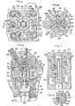
- Figure 1 is an elevational view partly in section showing the hydraulic head of a fuel injection pump in accordance with the present invention having a fuel injection nozzle and holder assembly of a preferred type connected thereto;
- Figure 2 is an enlarged sectional elevational view of the fuel injection nozzle shown in Figure 1;
- Figure 3 is an enlarged sectional view taken along the line 3-3 of Figure 2 showing details of the nozzle spacer;
- Figure 4 is a plan view of the fuel injection pump hydraulic head shown in Figure 1;
- Figure 5 is a sectional view taken along the lines 5-5 of Figure 4 with the pump plunger shown during the'fuel injection stroke;
- Figure 6 is an enlarged sectional view taken along the line 6-6 of Figure 5;
- Figure 7 is a sectional view taken along the lines 7-7 of Figure 6;
- Figure 8 is a sectional view taken along the lines 8-8 of Figure 7;
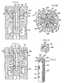
- Figure 9 is a sectional view taken along the lines 9-9 of Figure 6 illustrating the fuel path for injection line fill;
- Figure 10 is a view similar to Figure 6 but with the pump plunger shown during the suction stroke;
- Figure 11 is a sectional view taken along the line 11-11 of Figure 10 showing the fuel flow from the fuel supply ports into the pumping chamber;
- Figure 12 is a sectional view taken along the line 12-12 of Figure 11 showing the arrangement of the fuel supply ports;
- Figure 13 is a partial isometric view of the pump plunger shown in Figure 11, and
- Figure 14 is an enlarged development view showing the pump plunger and cylinder surfaces superimposed and illustrating the path of the plunger elements along the cylinder surface.
- With reference to the drawings and particularly Figure 1 thereof, a
hydraulic head 16 of afuel injection pump 18 is shown connected by aninjection line 20 to a fuel injection nozzle andholder assembly 22. Although the improvements of the present invention are located within thehydraulic head 16, an understanding of the fuel passages downstream of the hydraulic head is necessary to an appreciation of the inventive features and accordingly the nozzle andholder assembly 22 will be described in detail. Thepump 18 is of the single plunger multi-cylinder type and the nozzle andholder assembly 22 and itsconnecting injection line 20 are but one of a plurality of such assemblies required for an operative system, the number being equal to the number of engine cylinders. As will be presently apparent, thepump 18 shown has been designed for a six cylinder engine although the invention is applicable to pumps having any desired number of fuel outlets. - The nozzle and
holder assembly 22 comprises a generallycylindrical nozzle holder 24 having a threadedupper end 26 to which theinjection line 20 is secured in sealing relation by means of a nut 28. The holder includes a threadedlower end 30 against which aspacer 32 andnozzle body 34 are secured in coaxially aligned relation by acap nut 36 which engages ashoulder 38 of the nozzle body. - The
nozzle body 34 includes a central bore 40 (see Figure 2) extending through the upper end thereof and which terminates at its lower end adjacent aconical valve seat 42. Anozzle valve 44 is slidably disposed within thebore 40 and terminates at its lower end in aconical tip 46 adapted to cooperate with thevalve seat 42. Thebore 40 includes anannulus 48, and thevalve 44 is reduced in diameter within and below theannulus 48 to form anannular passage 50 between theannulus 48 and thevalve seat 42. The nozzle body terminates at its lower end in anozzle tip 52 having a hollowinterior chamber 54, known as a "sac", which communicates with the passage formed between the valve seat and the valve tip when the valve is in the raised position illustrated.Orifices 56 in thenozzle tip 52 permit fuel under pressure to pass from thesac 54 into the combustion chamber of an engine in a predetermined spray pattern. - An
extension 58 of thevalve 44 extends concentrically from theupper end 60 of the valve, passing through an enlargedbore 62 in thespacer 32 into aspring chamber 63 in theholder 24. The upper end of thevalve extension 58 engages aspring guide 64 on which is seated the lower end of acompression coil spring 66 disposed within thespring chamber 63 and bearing at its upper end against the end of the chamber. Thespring 66 maintains a closing force on thevalve 44, which force must be overcome by the injection pressure of the fuel in order to open the valve as described below. - The fuel passage of the
injection line 20 communicates with apassage 68 in the nozzle holder, apassage 70 in thespacer 32, and apassage 72 in the nozzle body opening into theannulus 48. Metered quantities of fuel in the proper timed relation to the engine cycle are pumped by thepump 18 through theinjection line 20 and thepassages annulus 48 and thence to theannular passage 50, whereupon the pressure acting on the differential area, between the upper part of thevalve 44 and the non-exposed lower area of thevalve seat 42, creates an opening force sufficient to overcome the force of thespring 66 and lift thevalve 44 until theupper end 60 of the valve engages the bottom face of thespacer 32. The high pressure fuel enters thesac 54 and passes through the small spray orifi.;es 56 whereupon it is atomized for burning within the engine combustion chamber (not shown). - As shown in Figures 2 and 3, the
spacer 32 is maintained in the proper angular relationship with theholder 24 and thenozzle body 34 bydowel pins 74 in thespacer 32 which fit into alignedbores holder 24 and thenozzle body 34. In view of the possibility that the spacer may be assembled upside down, an alternative passage 70a is provided in the spacer which in the inverted position of the spacer will connect thepassage 68 of the holder and thepassage 72 of the valve body. - The illustrated nozzle and
holder assembly 22 is of the leakless type, meaning that fuel leakage around the upper end of thevalve 44 which passes into thespring chamber 63 is not removed to a sump as in the conventional nozzle. Instead, this fuel is permitted to leak back along the valve during the periods between injection, and the pressure in the injection lines is reduced sufficiently between injections to prevent a pressure build-up in the spring chamber sufficient to prevent the proper opening of the valve. Since the pressure build-up in the spring chamber will effectively augment the force of the spring in closing the valve, it is important that this pressure build-up be uniform in each of the engine nozzles. Since theupper end 60 of thevalve 44 bearing against the lower surface of thespacer 32 may cause a sealing of thebore 62 during the injection interval, and thus prevent a predicatable pressure build-up in thespring chamber 63, means is provided to ensure communication between thespring chamber 63 and the upper end of thebore 40 in the event that such a sealing relationship should take place between the upper end of the valve and the lower surface of the spacer. This means comprises acounterbore 80 in the upper end of thebore 40 and apassage 82 in thespacer 32 extending between thecounterbore 80 and thespring chamber 63. Should the bore 62 become sealed during the injection interval, the leakage high pressure fuel passing between thevalve 44 and thebore 40 will pass, by means of thecounterbore 80 and thepassage 82, into thespring chamber 63. It should be noted that the sectional views of Figures 1 and 2, insofar as thespacer 32 is concerned, are not true sections but have been modified to show, in a single sectional view, thepassage 70, thepassage 82 and one of the dowel pins 76. - The details of the hydraulic head are illustrated in Figures 4-13. With particular reference to Figure 5, the
hydraulic head 16 is seen to comprise a substantially cylindrical assemblage which is disposed within avertical bore 84 of thefuel pump housing 86. Thehydraulic head 16 is sealed within thebore 84 by means of alower flange 88 thereof seated on aseal ring 90 disposed on ashoulder 92 of thehousing 86. The hydraulic head is sealed along its upper periphery by aseal ring 94. Between theflange 88 and theseal ring 94, the hydraulic head is set back from thebore 84 to establish an annular gallery between the hydraulic head body and the casing bore. Anannular portion 96 of the hydraulic head, which is known as a gallery guard, is sealed to thebore 84 byseal ring 98, and divides the gallery into alower gallery 100 and anupper gallery 102. Fuel to be pumped is delivered under a relatively low pressure, for example 1.4 to 2.1 kg/cm2 (20 to 30 psi), into theupper gallery 102 through an inlet port 104, the upper gallery constituting a fuel supply chamber. The low pressure fuel is supplied from an engine driven gear pump (not shown) and is delivered to the hydraulic head after passing through several filtration stages (also not shown). Although thelower gallery 100 is sealed from theupper gallery 102 by thegallery guard 96, fluid communication is provided between the lower and upper galleries by ableed passage 106 which serves an important function as described herebelow. - The
hydraulic head 16 includes a centralvertical bore 108 within which a pumping and distributingplunger 110 is slidably and rotatably disposed. Thebore 108, which passes completely through thehydraulic head 16, is closed at its upper end by aplug 112 sealed therein byseal ring 114 and secured by ascrew 116. Afuel pumping chamber 118 is formed within thebore 108 between the top of theplunger 110 and theplug 112. - The
plunger 110 is actuated by acamshaft 120 driven by the engine on which the pump is mounted. The camshaft includes acam 122 which engages aroller 134 of atappet 136 abutting the lower end of theplunger 110. Acompression spring 138 holds the plunger and tappet against the cam. Rotation of thecamshaft 120 will accordingly produce a reciprocatory movement of theplunger 110 by means of the cooperation of thecam 122, thetappet 136 and thespring 138. - Rotation of the
plunger 110 is also produced by therotating camshaft 120 which is geared to agovernor shaft 140. Agear 142 on thecamshaft 140 meshes with aface gear 144 having ahub portion 146 which is slidably keyed to the lower end of the plunger to produce rotation on theplunger 110 while permitting a reciprocatory movement of the plunger with respect thereto. - Since the pump illustrated is designed to supply fuel to a six cylinder engine, there will be six axial pumping strokes of the
plunger 110 for each complete revolution of the plunger. The plunger will accordingly rotate 60° during each pumping cycle. - The low pressure fuel passes from the upper gallery 102 (the fuel supply chamber) into the
pumping chamber 118 during a suction stroke of theplunger 110 throughradial fuel passages 148 and upper andlower fuel ports respective fuel passage 148 and thebore 108. In order to permit entry of fuel from theports 150 into thepumping chamber 118 before theupper end 154 of the plunger has cleared theupper ports 150 on the downstroke of the plunger,notches 156 are provided in the edge of theplunger 110 at 60° intervals. Thenotches 156 are located so as to open the pumping chamber to theupper ports 150 during the downstroke of the plunger but to rotate out of phase with theports 150 during the upstroke of the plunger. As shown in Figures 6 and 10, there are sixfuel passages 148 and six pairs offuel ports 150 . and 152, which are spaced at 60° intervals. As shown in Figures 10 and 11, during the plunger downstroke (the suction stroke) thenotches 156 are rotated into alignment with theports 150 so that fluid communication is provided simultaneously between all six of thepassages 148 and thepumping chamber 118. During the plunger upstroke (the compression or pumping stroke), thenotches 156 are rotated out of alignment with the ports as shown in Figure 6. - The
plunger 110 includes acoaxial bore 158 opening into thepumping chamber 118 at its upper end. Adelivery port 160 communicating with thebore 158 opens into adistributor slot 162 which sequentially communicates withfuel outlet passages 164 during the upstroke (the pumping stroke) of theplunger 110 as illustrated in Figures 7 and 8. There are sixoutlet passages 164 spaced at 60° intervals and, as shown in Figures 5 and 6, each of theoutlet passages 164 communicates with acentral passage 166 of a threadedconnector 168 threadedly attached to thehydraulic head 16. As shown in Figure 1, theinjection line 20 is attached to theconnector 168 by means of a nut 1.70. - As shown in Figure 11, a
plunger balancing port 172 and aslot 174 are diametrically opposed from theport 160 and thedistributor slot 162 to expose thebore 108 to the high pumping pressure within the plunger bore 158 during the injection interval. Theslot 174 is of the same area as theslot 162 to provide a balancing of the high pressure forces and ' prevent binding of the plunger. -
Auxiliary fill ports 176 are provided in theplunger 110 which open into aspill sump 178 when the plunger is in the lower part of its filling cycle. Thespill sump 178 comprises a transverse chamber extending through the hydraulic head and opening into thelower gallery 100, the spill sump and the lower gallery together defining a spill chamber. -
Transverse spill ports 180 in theplunger 110 communicating with the plunger bore 158 open into thespill sump 178. Afuel control sleeve 182 slidably disposed on theplunger 110 within thespill sump 178 is positioned by a linkage (not shown) from the governor and covers thespill ports 180 during injection. When thespill ports 180 clear the upper edge of thecontrol sleeve 182, the high fuel pressure in thepumping chamber 118 and the plunger bore 158 is dropped to the pressure within the spill chamber, thereby cutting off injection. The higher the position of thefuel control sleeve 182 in thespill sump 178, the later in the pumping stroke will thespill ports 180 open into the spill sump, and hence the greater will be the quantity of fuel injected. - Since the fuel pump disclosed does not utilize a delivery valve, means is provided to maintain a uniform residual pressure in each
fuel outlet passage 164 anddelivery line 20 as well as the fuel passages connected therewith within the nozzle holder and nozzle, which line and passages collectively are referred to as a fuel distribution passage. This means comprises means for placing the fuel distribution passages in communication with the low pressure fuel in theupper gallery 102 between injection intervals. A pair offlats plunger 110 are disposed on the opposite side thereof from thedistributor slot 162 and in the axial direction of theplunger 110 so as to place the lowerfuel inlet ports 152 in communication with certain of the idlefuel outlet passages 164 as shown in Figures 8 and 9. This arrangement ensures a predetermined pressure in the fuel distribution passages so that the fuel delivery through the passages to each nozzle will be both uniform and predictable. - In operation, during the pumping stroke of the plunger as shown in Figure 6, and the development view of Figure 14, the
plunger 110 is rotationally disposed so that theplunger notches 156 lie between the upperfuel inlet ports 150 while thedistributor slot 162 communicates with one of theoutlet passages 164 to direct high pressure fuel thereinto as shown in Figure 7. At the same time, as shown in Figures 8, 9 and 14, theflats lower fuel ports 152 with three of theidle outlet passages 164 to produce a uniform fuel pressure in these passages. - Injection is terminated when the
spill port 180 of the plunger clears the upper edge of thespill sleeve 182, at which point the high pressure fuel in the fuel distribution passages as well as in the plunger passages and the pumping chamber is released to the spill chamber. Since the spill chamber is sealed except for thebleed passage 106, the spill chamber pressure will build up momentarily upon fuel cutoff to restrict the fuel flow from the distribution passages, thereby minimizing the opportunity for voids to form in the passages. Thebleed passage 106, which in a preferred embodiment of the invention has a minimum diameter of only 0.75 mm (0.030 inches), prevents the average pressure in the spill chamber from becoming unduly high. In a preferred embodiment of the invention, the average pressure in the spill chamber is approximately 20-30 kg/cm2 (300-400 psi). Because of the cyclical nature of the pump operation, the pressure in the spill chamber will also be cyclical, peaking just after fuel cutoff. The present invention is particularly effective during low speed operation when longer time periods between injection intervals would otherwise permit more fuel flow from the distribution passages. - During the suction stroke of the
plunger 110, as shown in Figure 11 and in the dotted line position of the plunger in Figure 14, thenotches 156 of the plunger communicate with theupper fuel ports 150 to permit a filling of the fuel injection chamber even before the top of the plunger clears the upper edge of theports 1 50. Theflats lower fuel ports 152 although they continue to communicate with certain of theoutlet passages 164. Thedistributor slot 162, as also shown in Figure 14, has passed out of communication with one of theoutlet passages 164 and is on its way to the next passage through which fuel will be distributed. - Since the use of an annular fuel supply gallery surrounding the central portion of a pump hydraulic head is a feature common to several commercially popular single plunger pump embodiments, the particular embodiment of the present invention disclosed including the gallery guard feature with the bleed passage therein can be appreciated as a relatively simple modification of a conventional pump design for producing the necessary separate spill and fuel supply chambers with a bleed passage therebetween. Although the spill
chamber bleed passage 106 could communicate with another low pressure fuel sump other than the pump fuel supply chamber defined by theupper gallery 102, it will be apparent that the proximity of the fuel supply chamber and the need therein of a pressurized fuel makes the fuel supply chamber the obvious choice for achieving pressure relief in the spill chamber. - The reduction of the fuel distribution passage pressure between injection intervals to a level of a few tens of kilograms per square centimetre (several hundred pounds per square inch) from a peak pressure normally in excess of 700 kg/cm2 (10,000 psi), permits the fuel leaking into the
spring chamber 63 of the leakless nozzle, to leak back out into the injection passages, thereby preventing a build-up of pressure in the spring chamber which might interfere with the proper lifting of thenozzle valve 44. The use of a leakless nozzle of this type is not only desirable due to the elimination of the usual leakoff fittings, but further because of the spring chamber which is lower at low loads and low speeds resulting in a desirable reduction of nozzle opening and closing pressures under these conditions. - Manifestly, changes in details of construction can be effected by those skilled in the art without departing from the scope of the present invention as defined in the following claims.
Claims (10)
Applications Claiming Priority (2)
| Application Number | Priority Date | Filing Date | Title |
|---|---|---|---|
| US05/972,516 US4229148A (en) | 1978-12-22 | 1978-12-22 | Fuel injection pump |
| US972516 | 1978-12-22 |
Publications (2)
| Publication Number | Publication Date |
|---|---|
| EP0013140A1 EP0013140A1 (en) | 1980-07-09 |
| EP0013140B1 true EP0013140B1 (en) | 1983-01-12 |
Family
ID=25519744
Family Applications (1)
| Application Number | Title | Priority Date | Filing Date |
|---|---|---|---|
| EP79302983A Expired EP0013140B1 (en) | 1978-12-22 | 1979-12-20 | Fuel injection pump |
Country Status (5)
| Country | Link |
|---|---|
| US (1) | US4229148A (en) |
| EP (1) | EP0013140B1 (en) |
| JP (1) | JPS55112854A (en) |
| CA (1) | CA1122863A (en) |
| DE (1) | DE2964515D1 (en) |
Families Citing this family (8)
| Publication number | Priority date | Publication date | Assignee | Title |
|---|---|---|---|---|
| US4374511A (en) * | 1980-12-22 | 1983-02-22 | Ford Motor Company | Fuel injection pump with distributor type fuel control |
| DE3049366A1 (en) * | 1980-12-29 | 1982-07-29 | Spica S.p.A., Livorno | FUEL DISTRIBUTOR INJECTION PUMP FOR COMBUSTION ENGINES |
| DE19636896C1 (en) * | 1996-09-11 | 1998-05-07 | Daimler Benz Ag | Fuel injection nozzle for internal combustion engines |
| US6009850A (en) * | 1998-04-10 | 2000-01-04 | Alfred J. Buescher | High-pressure dual-feed-rate injector pump with grooved port-closing edge |
| US5870996A (en) * | 1998-04-10 | 1999-02-16 | Alfred J. Buescher | High-pressure dual-feed-rate injector pump with auxiliary spill port |
| US6360727B1 (en) | 2000-03-14 | 2002-03-26 | Alfred J. Buescher | Reduce initial feed rate injector with fuel storage chamber |
| US7318416B1 (en) | 2005-04-07 | 2008-01-15 | Stewart Howard C | Liquid fuel pump |
| US10865754B2 (en) * | 2017-04-05 | 2020-12-15 | Progress Rail Services Corporation | Fuel injector having needle tip and nozzle body surfaces structured for reduced sac volume and fracture resistance |
Family Cites Families (13)
| Publication number | Priority date | Publication date | Assignee | Title |
|---|---|---|---|---|
| DE489502C (en) * | 1925-01-15 | 1930-01-17 | Friedr Deckel | Device for introducing liquid fuels into internal combustion engines |
| DE492379C (en) * | 1925-08-20 | 1930-02-22 | Friedr Deckel | Fuel distributor with rotating distribution slide for multi-cylinder injection engines |
| US2518473A (en) * | 1949-02-19 | 1950-08-15 | American Bosch Corp | Fuel injection pump |
| US2640419A (en) * | 1950-05-23 | 1953-06-02 | Cav Ltd | Liquid fuel injection pump for internal-combustion engines |
| DE1103686B (en) * | 1958-09-24 | 1961-03-30 | Bosch Gmbh Robert | Fuel injection pump for multi-cylinder internal combustion engines |
| FR1450316A (en) * | 1964-10-20 | 1966-05-06 | Allis Chalmers Mfg Co | Fuel injection pump |
| US3348488A (en) * | 1965-12-07 | 1967-10-24 | Allis Chalmers Mfg Co | Distributor fuel injection pump with precharging and pilot injection |
| US3440964A (en) * | 1966-12-09 | 1969-04-29 | Ambac Ind | Fuel injection pump |
| US3420179A (en) * | 1967-06-22 | 1969-01-07 | Ambac Ind | Plunger balancing arrangement for fuel injection pumps |
| US3689200A (en) * | 1971-04-19 | 1972-09-05 | Ambac Ind | Fuel temperature compensator for fuel injection pumps |
| US3818882A (en) * | 1972-03-27 | 1974-06-25 | O Leonov | Fuel system of internal combustion engine |
| JPS4971319A (en) * | 1972-11-14 | 1974-07-10 | ||
| DE2349581C2 (en) * | 1973-10-03 | 1983-10-13 | Robert Bosch Gmbh, 7000 Stuttgart | Fuel distributor injection pump for internal combustion engines |
-
1978
- 1978-12-22 US US05/972,516 patent/US4229148A/en not_active Expired - Lifetime
-
1979
- 1979-12-19 CA CA342,205A patent/CA1122863A/en not_active Expired
- 1979-12-20 DE DE7979302983T patent/DE2964515D1/en not_active Expired
- 1979-12-20 EP EP79302983A patent/EP0013140B1/en not_active Expired
- 1979-12-21 JP JP16573979A patent/JPS55112854A/en active Pending
Also Published As
| Publication number | Publication date |
|---|---|
| US4229148A (en) | 1980-10-21 |
| JPS55112854A (en) | 1980-09-01 |
| EP0013140A1 (en) | 1980-07-09 |
| CA1122863A (en) | 1982-05-04 |
| DE2964515D1 (en) | 1983-02-17 |
Similar Documents
| Publication | Publication Date | Title |
|---|---|---|
| US3951117A (en) | Fuel supply system for an internal combustion engine | |
| US4693227A (en) | Multi-fuel injection system for an internal combustion engine | |
| US3943902A (en) | Fuel injection pumping apparatus | |
| US8011349B2 (en) | Fuel injection system | |
| EP0405753B1 (en) | Fuel-injection pump with reverse flow venting | |
| US4229148A (en) | Fuel injection pump | |
| US5700139A (en) | Fuel injection pump of the distributor type with a magnetically actuated valve member of a switching valve connected to a low-pressure piston | |
| EP0413453B1 (en) | Fuel pumping apparatus | |
| US4550702A (en) | Spill control system for distributor pump | |
| US4537352A (en) | Fuel injection apparatus | |
| EP0382388B1 (en) | Fuel injection pump | |
| US4204506A (en) | Fuel delivery system | |
| US3744465A (en) | Hydraulic shuttle vavle for fuel injection pumps | |
| US4266728A (en) | Leakless fuel injection nozzle and holder assembly | |
| CA1052363A (en) | Metering valve for fuel injection | |
| US5413081A (en) | Fuel pumps | |
| US5044899A (en) | Fuel pumping apparatus | |
| US4232644A (en) | Fuel pumping apparatus | |
| US4458649A (en) | Fuel injection pump for internal combustion engines | |
| EP0055654A1 (en) | Single solenoid floating piston distributor pump | |
| EP0372713B1 (en) | Fuel injection pump | |
| US3420179A (en) | Plunger balancing arrangement for fuel injection pumps | |
| US3440964A (en) | Fuel injection pump | |
| JP2791898B2 (en) | Distribution type fuel injection pump | |
| JP2512893B2 (en) | Fuel injector |
Legal Events
| Date | Code | Title | Description |
|---|---|---|---|
| PUAI | Public reference made under article 153(3) epc to a published international application that has entered the european phase |
Free format text: ORIGINAL CODE: 0009012 |
|
| AK | Designated contracting states |
Designated state(s): DE FR GB IT NL SE |
|
| 17P | Request for examination filed |
Effective date: 19801124 |
|
| ITF | It: translation for a ep patent filed | ||
| GRAA | (expected) grant |
Free format text: ORIGINAL CODE: 0009210 |
|
| AK | Designated contracting states |
Designated state(s): DE FR GB IT NL SE |
|
| REF | Corresponds to: |
Ref document number: 2964515 Country of ref document: DE Date of ref document: 19830217 |
|
| ET | Fr: translation filed | ||
| ITTA | It: last paid annual fee | ||
| EAL | Se: european patent in force in sweden |
Ref document number: 79302983.6 |
|
| PGFP | Annual fee paid to national office [announced via postgrant information from national office to epo] |
Ref country code: FR Payment date: 19961108 Year of fee payment: 18 |
|
| PGFP | Annual fee paid to national office [announced via postgrant information from national office to epo] |
Ref country code: SE Payment date: 19961115 Year of fee payment: 18 |
|
| PGFP | Annual fee paid to national office [announced via postgrant information from national office to epo] |
Ref country code: GB Payment date: 19961121 Year of fee payment: 18 |
|
| PGFP | Annual fee paid to national office [announced via postgrant information from national office to epo] |
Ref country code: DE Payment date: 19961125 Year of fee payment: 18 |
|
| PGFP | Annual fee paid to national office [announced via postgrant information from national office to epo] |
Ref country code: NL Payment date: 19961126 Year of fee payment: 18 |
|
| PG25 | Lapsed in a contracting state [announced via postgrant information from national office to epo] |
Ref country code: GB Free format text: LAPSE BECAUSE OF NON-PAYMENT OF DUE FEES Effective date: 19971220 |
|
| PG25 | Lapsed in a contracting state [announced via postgrant information from national office to epo] |
Ref country code: SE Free format text: LAPSE BECAUSE OF NON-PAYMENT OF DUE FEES Effective date: 19971221 |
|
| PG25 | Lapsed in a contracting state [announced via postgrant information from national office to epo] |
Ref country code: FR Free format text: THE PATENT HAS BEEN ANNULLED BY A DECISION OF A NATIONAL AUTHORITY Effective date: 19971231 |
|
| PG25 | Lapsed in a contracting state [announced via postgrant information from national office to epo] |
Ref country code: NL Free format text: LAPSE BECAUSE OF NON-PAYMENT OF DUE FEES Effective date: 19980701 |
|
| GBPC | Gb: european patent ceased through non-payment of renewal fee |
Effective date: 19971220 |
|
| NLV4 | Nl: lapsed or anulled due to non-payment of the annual fee |
Effective date: 19980701 |
|
| PG25 | Lapsed in a contracting state [announced via postgrant information from national office to epo] |
Ref country code: DE Free format text: LAPSE BECAUSE OF NON-PAYMENT OF DUE FEES Effective date: 19980901 |
|
| EUG | Se: european patent has lapsed |
Ref document number: 79302983.6 |
|
| REG | Reference to a national code |
Ref country code: FR Ref legal event code: ST |
|
| PLBE | No opposition filed within time limit |
Free format text: ORIGINAL CODE: 0009261 |
|
| STAA | Information on the status of an ep patent application or granted ep patent |
Free format text: STATUS: NO OPPOSITION FILED WITHIN TIME LIMIT |