EP0012128A1 - Spring assembly for floating seat ring - Google Patents
Spring assembly for floating seat ring Download PDFInfo
- Publication number
- EP0012128A1 EP0012128A1 EP79890026A EP79890026A EP0012128A1 EP 0012128 A1 EP0012128 A1 EP 0012128A1 EP 79890026 A EP79890026 A EP 79890026A EP 79890026 A EP79890026 A EP 79890026A EP 0012128 A1 EP0012128 A1 EP 0012128A1
- Authority
- EP
- European Patent Office
- Prior art keywords
- wave
- seat ring
- spring
- pair
- nodes
- Prior art date
- Legal status (The legal status is an assumption and is not a legal conclusion. Google has not performed a legal analysis and makes no representation as to the accuracy of the status listed.)
- Granted
Links
- 238000007789 sealing Methods 0.000 abstract description 8
- 230000002093 peripheral effect Effects 0.000 description 3
- 239000000314 lubricant Substances 0.000 description 1
- 238000000034 method Methods 0.000 description 1
- 230000000717 retained effect Effects 0.000 description 1
Images

Classifications
-
- F—MECHANICAL ENGINEERING; LIGHTING; HEATING; WEAPONS; BLASTING
- F16—ENGINEERING ELEMENTS AND UNITS; GENERAL MEASURES FOR PRODUCING AND MAINTAINING EFFECTIVE FUNCTIONING OF MACHINES OR INSTALLATIONS; THERMAL INSULATION IN GENERAL
- F16K—VALVES; TAPS; COCKS; ACTUATING-FLOATS; DEVICES FOR VENTING OR AERATING
- F16K5/00—Plug valves; Taps or cocks comprising only cut-off apparatus having at least one of the sealing faces shaped as a more or less complete surface of a solid of revolution, the opening and closing movement being predominantly rotary
- F16K5/08—Details
- F16K5/14—Special arrangements for separating the sealing faces or for pressing them together
- F16K5/20—Special arrangements for separating the sealing faces or for pressing them together for plugs with spherical surfaces
- F16K5/201—Special arrangements for separating the sealing faces or for pressing them together for plugs with spherical surfaces with the housing or parts of the housing mechanically pressing the seal against the plug
Definitions
- annular wave springs have been utilized to urge seat rings into sealing engagement with an associated valve member, such as a ball or gate.
- annular undulated wave springs are illustrated to urge a seat member into sealing engagement with an associated ball valve member.
- the prior art does not show the use of a plurality of annular undulated wave springs about a seat ring which are held in an oriented relation to each other so that contiguous wave springs are staggered with respect to the nodes of the springs.
- the present invention is directed to a spring assembly for a floating seat ring to urge the seat ring into sealing engagement with the adjacent valve member. It is particularly adapted to a hall valve seat ring in which the seat ring has a relatively large floating movement to permit the seat ring to be retracted to a position adequate to permit the removal of the ball valve member in a ball valve for replacement of the seat assembly or sealing element.
- the improved spring assembly is mounted in the spring pocket formed between the rear face of the seat ring and an opposed annular shoulder formed by a counterbore in the valve body at the valve chamber.
- the spring assembly comprises a plurality of undulated annular wave springs fitting about the seat ring, each pair of contiguous wave springs being staggered with respect to each other so that the front nodes of one wave spring in the contiguous pair is in opposed contact relation to the rear nodes in the other wave spring of the contiguous pair.
- a flat portion on the outer circumference of the seat ring is in nested relation to a cooperating flat portion on the inner circumference of the wave springs and maintain the wave springs in an oriented staggered relation thereby to prevent any relative circumferential movement of the wave springs with respect to each other.
- a so-called top entry ball valve is shown in which the upper cover plate is first removed, and then the seat rings and ball are easily removed from the valve body while the valve is in place in a flowline.
- the rotative movement of the b O li is utilized to cam the seat rings away from the ball to a fully retracted position where they are releasably retained while the ball is removed.
- a camming tool is usually utilized with the ball to cam the seat rings away from the ball.
- the present invention is particularly adapted for use with the so-called top entry ball valve arrangement shown in application Serial No. 902,324 but has utility with any floating seat arrangement where it is desired to urge continuously the seat ring into engagement with an adjacent valve member.
- a ball valve structure is shown generally at 10 including a valve body 12 having flow passages 14.
- a valve chamber 16 between flow passages 14 has a ball valve member 18 mounted therein for movement between open and closed positions.
- a stem 20 secured to ball valve member 18 has a handle 22 which may be gripped for moving ball valve 18 between open and closed positions relative to flow passages 14.
- a lower trunnion 24 is mounted on the lower side of ball valve member 18.
- An upper cover plate 26 is removably connected to valve body 12 by suitable studs 28.
- Ball valve member 18 has a flow passage 30 therethrough which is adapted to be aligned with flow passages 14 when moved to an open position thereof as shown in Fig. 1.
- Valve body 12 at the juncture of flow passages 14 with valve chamber 16 has a pair of enlarged bore portions or counterbores defined by intermediate diameter bore portion 32 and enlarged diameter bore portion 34.
- Intermediate diameter bore portion 32 defines a tapered shoulder or abutment 36 and enlarged diameter bore portion 34 defines a shoulder or abutment 38 which faces valve chamber 16.
- a seat ring generally indicated at 40 is mounted within counterbores 32 and 34 for floating longitudinal movement relative to ball valve member 18.
- Seat ring 40 has an inner circumferential or peripheral surface 42, a small diameter outer peripheral surface 44, and a large diameter outer peripheral surface 46.
- O-rings 48 and 50 are mounted in respective grooves 49, 51 in respective outer circumferential surfaces 44 and 46.
- 0-rings 48 and 50 are adapted to block or restrict the flow of any lubricant inserted therebetween.
- Seat ring 40 has a rear face or shoulder defined at 52 extending between circumferential surfaces 44 and 46.
- a resilient sealing element 54 extends from the front face of seat ring 40 and is adapted to engage in sealing relation the adjacent sealing surface of ball valve member 18.
- Spring assembly 56 comprises a plurality of wave springs with alternate wave springs being indicated at 58 and intervening wave springs being indicated at 60.
- Each contiguous pair of wave springs 58, 60 is arranged in a staggered relation to each other.
- Each wave spring 58, 60 has four front nodes indicated at 58A and 60A respectively. The nodes are arranged at a 90° relation to each other about the circumference of the respective wave spring.
- rear nodes 58B and 60B are provided about the circumference of respective wave springs 58, 60 between front nodes 58A and 60A.
- Front and rear nodes on a contiguous pair of wave springs are in opposed relation to each other.
- rear nodes 58B on spring 58 are in opposed relation to front nodes 60A on the contiguous wave spring 60.
- rear nodes 60B on wave spring 60 are in contact relation with front nodes 58A on spring 58 of the contiguous pair.
- surface 44 has a flat portion 44A positioned thereon.
- the inner circumference 62 of each wave spring 58, 60 has an inner flat portion 64 which is arranged in nested relation to flat surface 44A on seat ring 40.
- wave springs 58 and 60 are prevented from any rotation after being positioned on seat ring 40.
- Wave springs 58 and 60 are generally identical but upon initial positioning on seat ring 40, wave springs 60 are rotated around 45° with respect to wave springs 58.
- flat portion 64 on wave springs 60 is positioned with respect to the nodes at a location staggered forty-five degrees (45 0 ) circumferentially from flat portion 64 on wave springs 58 with respect to its nodes.
- rear nodes 60B on springs 60 are in contact relation with the front nodes 58A on springs 58 thereby to provide a maximum expansion of wave springs 58 and 60 when arranged in a plurality of springs about a seat ring.
- seat ring 40 is shown as cammed rearwardly to its rearmost position with springs 58 and 60 in a generally flattened position thereof.
- a camming tool indicated generally at 70 and having a front cam face 72 is inserted in opening 30 of valve member 18 after cover plate 26 is removed and valve member 18 is rotated around forty-five degrees (45 0 ) from its open position.
- surface 72 engages the front face of seat ring 40 to urge seat ring 40 to the rearmost position indicated in Fig. 2.
- a retainer is actuated to hold seat ring 40 in retracted position.
- the retainer comprises a housing 74 threaded within valve body 12 and having an internally threaded central bore 76.
- a threaded plunger indicated generally at 78 has an integral head 80 on its outer end and an elongated pin 82 on its inner end extending from body 84.
- head 80 Upon rotation of head 80 by a suitable wrench or the like, the inner end of pin 82 engages wave springs 58, 60 to compress springs 58, 60 against the adjacent circumferential surface 44 of seat ring 40 to hold seat ring 40 in a retracted position.
- Wave springs 58, 60 are made inoperable when engaged by pin 82 in a tight frictional relation. In this position, ball 18 may be removed.
- seal ring 40 may be released from retracted position by loosening plunger 78 and then removed from valve body 12. New or repaired seat rings 40 may be reinserted in valve body 12 and moved to a retracted position where they are held by the retainers to permit reinsertion of ball valve 18.
Landscapes
- Engineering & Computer Science (AREA)
- General Engineering & Computer Science (AREA)
- Mechanical Engineering (AREA)
- Taps Or Cocks (AREA)
- Springs (AREA)
Abstract
Description
- Heretofore, annular wave springs have been utilized to urge seat rings into sealing engagement with an associated valve member, such as a ball or gate. As shown in U.S. Patent No. 2,548,128 to J. R. Snyder dated April 10, 1951, and U.S. Patent No. 3,387,815 to C. G. F. Richards dated June 11, 1968, annular undulated wave springs are illustrated to urge a seat member into sealing engagement with an associated ball valve member. However, the prior art does not show the use of a plurality of annular undulated wave springs about a seat ring which are held in an oriented relation to each other so that contiguous wave springs are staggered with respect to the nodes of the springs.
- The present invention is directed to a spring assembly for a floating seat ring to urge the seat ring into sealing engagement with the adjacent valve member. It is particularly adapted to a hall valve seat ring in which the seat ring has a relatively large floating movement to permit the seat ring to be retracted to a position adequate to permit the removal of the ball valve member in a ball valve for replacement of the seat assembly or sealing element. The improved spring assembly is mounted in the spring pocket formed between the rear face of the seat ring and an opposed annular shoulder formed by a counterbore in the valve body at the valve chamber. The spring assembly comprises a plurality of undulated annular wave springs fitting about the seat ring, each pair of contiguous wave springs being staggered with respect to each other so that the front nodes of one wave spring in the contiguous pair is in opposed contact relation to the rear nodes in the other wave spring of the contiguous pair. A flat portion on the outer circumference of the seat ring is in nested relation to a cooperating flat portion on the inner circumference of the wave springs and maintain the wave springs in an oriented staggered relation thereby to prevent any relative circumferential movement of the wave springs with respect to each other.
- As illustrated in copending application Serial No. 902,324 filed May 3, 1978 and entitled "Means and Method for In-line Removal of Seat Rings in Ball Valves" a so-called top entry ball valve is shown in which the upper cover plate is first removed, and then the seat rings and ball are easily removed from the valve body while the valve is in place in a flowline. The rotative movement of the bOli is utilized to cam the seat rings away from the ball to a fully retracted position where they are releasably retained while the ball is removed. Thus, a relatively large floating movement of the seat rings is desired and necessary in order to permit the removal of the ball. A camming tool is usually utilized with the ball to cam the seat rings away from the ball. The present invention is particularly adapted for use with the so-called top entry ball valve arrangement shown in application Serial No. 902,324 but has utility with any floating seat arrangement where it is desired to urge continuously the seat ring into engagement with an adjacent valve member.
-
- Fig. 1 is a longitudinal section of a ball valve of the top entry type having floating seat rings, with the spring assembly comprising the present invention urging the seat rings into engagement with the adjacent ball member;
- Fig. 2 is an enlarged sectional view showing a seat ring cammed by the ball valve member into a retracted position and held in the retracted position by retaining means;
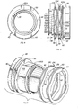
- Fig. 3 is a side elevation view of the seat ring when removed from the valve assembly shown in Fig. 1 and showing the spring assembly mounted about the outer circumference of the seat ring;
- Fig. 4 is a section taken generally along the line of 4-4 of Fig. 3; and
- Fig. 5 is a perspective of the seat ring and spring assembly shown in Figs. 3 and 4 with the wave springs of the spring assembly being removed from the seat ring.
- Referring now to the drawings, a ball valve structure is shown generally at 10 including a
valve body 12 havingflow passages 14. Avalve chamber 16 betweenflow passages 14 has aball valve member 18 mounted therein for movement between open and closed positions. Astem 20 secured toball valve member 18 has ahandle 22 which may be gripped for movingball valve 18 between open and closed positions relative toflow passages 14. Alower trunnion 24 is mounted on the lower side ofball valve member 18. Anupper cover plate 26 is removably connected tovalve body 12 bysuitable studs 28.Ball valve member 18 has aflow passage 30 therethrough which is adapted to be aligned withflow passages 14 when moved to an open position thereof as shown in Fig. 1. -
Valve body 12 at the juncture offlow passages 14 withvalve chamber 16 has a pair of enlarged bore portions or counterbores defined by intermediatediameter bore portion 32 and enlargeddiameter bore portion 34. Intermediatediameter bore portion 32 defines a tapered shoulder orabutment 36 and enlargeddiameter bore portion 34 defines a shoulder orabutment 38 which facesvalve chamber 16. A seat ring generally indicated at 40 is mounted withincounterbores ball valve member 18.Seat ring 40 has an inner circumferential orperipheral surface 42, a small diameter outerperipheral surface 44, and a large diameter outerperipheral surface 46. O-rings 48 and 50 are mounted inrespective grooves circumferential surfaces rings 48 and 50 are adapted to block or restrict the flow of any lubricant inserted therebetween.Seat ring 40 has a rear face or shoulder defined at 52 extending betweencircumferential surfaces resilient sealing element 54 extends from the front face ofseat ring 40 and is adapted to engage in sealing relation the adjacent sealing surface ofball valve member 18. - Mounted in the pocket formed between
rear face 42 and the opposedvalve body shoulder 38 is a spring assembly comprising the present invention and generally indicated by thenumeral 56.Spring assembly 56 comprises a plurality of wave springs with alternate wave springs being indicated at 58 and intervening wave springs being indicated at 60. Each contiguous pair ofwave springs wave spring rear nodes respective wave springs front nodes - Front and rear nodes on a contiguous pair of wave springs are in opposed relation to each other. For example,
rear nodes 58B onspring 58 are in opposed relation tofront nodes 60A on thecontiguous wave spring 60. Thus,rear nodes 60B onwave spring 60 are in contact relation withfront nodes 58A onspring 58 of the contiguous pair. To hold the wave springs in oriented staggered relation and to prevent the wave springs from moving circumferentially aboutcircumferential surface 44 ofseat ring 40,surface 44 has a flat portion 44A positioned thereon. Theinner circumference 62 of eachwave spring flat portion 64 which is arranged in nested relation to flat surface 44A onseat ring 40. In this relation,wave springs seat ring 40.Wave springs seat ring 40,wave springs 60 are rotated around 45° with respect towave springs 58. Also,flat portion 64 onwave springs 60 is positioned with respect to the nodes at a location staggered forty-five degrees (450) circumferentially fromflat portion 64 onwave springs 58 with respect to its nodes. By this arrangement,rear nodes 60B onsprings 60 are in contact relation with thefront nodes 58A onsprings 58 thereby to provide a maximum expansion ofwave springs - Referring to Fig. 2,
seat ring 40 is shown as cammed rearwardly to its rearmost position withsprings front cam face 72 is inserted in opening 30 ofvalve member 18 aftercover plate 26 is removed andvalve member 18 is rotated around forty-five degrees (450) from its open position. Whenvalve member 18 is rotated to fullyopen position surface 72 engages the front face ofseat ring 40 to urgeseat ring 40 to the rearmost position indicated in Fig. 2. While held in this position bycam tool 70 at the open position, a retainer is actuated to holdseat ring 40 in retracted position. The retainer comprises a housing 74 threaded withinvalve body 12 and having an internally threadedcentral bore 76. A threaded plunger indicated generally at 78 has anintegral head 80 on its outer end and anelongated pin 82 on its inner end extending frombody 84. Upon rotation ofhead 80 by a suitable wrench or the like, the inner end ofpin 82 engageswave springs springs circumferential surface 44 ofseat ring 40 to holdseat ring 40 in a retracted position.Wave springs pin 82 in a tight frictional relation. In this position,ball 18 may be removed. Thenseal ring 40 may be released from retracted position by looseningplunger 78 and then removed fromvalve body 12. New or repairedseat rings 40 may be reinserted invalve body 12 and moved to a retracted position where they are held by the retainers to permit reinsertion ofball valve 18.
Claims (5)
Priority Applications (1)
| Application Number | Priority Date | Filing Date | Title |
|---|---|---|---|
| AT79890026T ATE1652T1 (en) | 1978-11-13 | 1979-08-17 | SPRING UNIT FOR FLOATING SEAT RING. |
Applications Claiming Priority (2)
| Application Number | Priority Date | Filing Date | Title |
|---|---|---|---|
| US96049978A | 1978-11-13 | 1978-11-13 | |
| US960499 | 1978-11-13 |
Publications (2)
| Publication Number | Publication Date |
|---|---|
| EP0012128A1 true EP0012128A1 (en) | 1980-06-11 |
| EP0012128B1 EP0012128B1 (en) | 1982-10-13 |
Family
ID=25503249
Family Applications (1)
| Application Number | Title | Priority Date | Filing Date |
|---|---|---|---|
| EP79890026A Expired EP0012128B1 (en) | 1978-11-13 | 1979-08-17 | Spring assembly for floating seat ring |
Country Status (8)
| Country | Link |
|---|---|
| EP (1) | EP0012128B1 (en) |
| JP (1) | JPS5565772A (en) |
| AR (1) | AR218393A1 (en) |
| AT (1) | ATE1652T1 (en) |
| AU (1) | AU525286B2 (en) |
| BR (1) | BR7906416A (en) |
| CA (1) | CA1111405A (en) |
| DE (1) | DE2963848D1 (en) |
Cited By (6)
| Publication number | Priority date | Publication date | Assignee | Title |
|---|---|---|---|---|
| EP0207755A3 (en) * | 1985-06-27 | 1988-03-02 | Yoneki Valves, Incorporated | Top entry trunnion ball valve |
| EP1672257A1 (en) * | 2004-12-15 | 2006-06-21 | Kohler Mira Limited | Thermostatic mixing valve |
| CN102052479A (en) * | 2010-12-23 | 2011-05-11 | 曾品其 | Composite sealing bidirectional straightway ball valve with four seats |
| EP2341269A1 (en) * | 2009-12-22 | 2011-07-06 | Valbart S.r.l. | Trunnion-mounted ball valve with reverse-piston effect |
| GB2539268A (en) * | 2015-06-12 | 2016-12-14 | Heap & Partners Ltd | Method of assembling a ball valve housing |
| CN106763861A (en) * | 2016-12-13 | 2017-05-31 | 白龙山 | Pneumatic bellows bellows-type hydraulic packing ball valve |
Families Citing this family (3)
| Publication number | Priority date | Publication date | Assignee | Title |
|---|---|---|---|---|
| US4388945A (en) * | 1982-01-04 | 1983-06-21 | Jamesbury Corporation | Valve assembly and disassembly device |
| JPS619679U (en) * | 1984-06-21 | 1986-01-21 | 日本ボ−ルバルブ株式会社 | Top entry type ball valve |
| JP2010261466A (en) * | 2009-04-09 | 2010-11-18 | Itotekkou Co Ltd | Gas cock |
Citations (7)
| Publication number | Priority date | Publication date | Assignee | Title |
|---|---|---|---|---|
| DE448817C (en) * | 1926-02-21 | 1927-08-30 | Fried Krupp Akt Ges | From stacked spring elements existing spring for buffer u. like |
| US2480529A (en) * | 1944-05-03 | 1949-08-30 | Thompson Prod Inc | Seal assembly |
| US2548128A (en) * | 1944-05-03 | 1951-04-10 | Thompson Prod Inc | Seal assembly for flow control devices |
| US3387815A (en) * | 1965-05-21 | 1968-06-11 | Richards & Co B C | Seat for ball-valve and ball-valve using this seat |
| FR1575883A (en) * | 1968-06-11 | 1969-07-25 | ||
| DE1808290A1 (en) * | 1968-11-12 | 1970-07-02 | Neue Argus Gmbh | Seal for ball plug in ball valves |
| DE2600946A1 (en) * | 1976-01-13 | 1977-07-14 | Boge Gmbh | Hydraulic shock absorber spring ring - has radially pitched undulations which control piston valve over dynamically uniform range |
Family Cites Families (4)
| Publication number | Priority date | Publication date | Assignee | Title |
|---|---|---|---|---|
| JPS4920315U (en) * | 1972-05-20 | 1974-02-20 | ||
| JPS4938916U (en) * | 1972-07-07 | 1974-04-05 | ||
| JPS5136035Y2 (en) * | 1973-04-26 | 1976-09-04 | ||
| JPS5330527B2 (en) * | 1975-02-03 | 1978-08-28 |
-
1979
- 1979-08-17 AT AT79890026T patent/ATE1652T1/en not_active IP Right Cessation
- 1979-08-17 EP EP79890026A patent/EP0012128B1/en not_active Expired
- 1979-08-17 DE DE7979890026T patent/DE2963848D1/en not_active Expired
- 1979-08-23 AR AR277824A patent/AR218393A1/en active
- 1979-08-27 CA CA334,631A patent/CA1111405A/en not_active Expired
- 1979-10-02 JP JP12726479A patent/JPS5565772A/en active Granted
- 1979-10-04 BR BR7906416A patent/BR7906416A/en unknown
- 1979-10-30 AU AU52306/79A patent/AU525286B2/en not_active Ceased
Patent Citations (7)
| Publication number | Priority date | Publication date | Assignee | Title |
|---|---|---|---|---|
| DE448817C (en) * | 1926-02-21 | 1927-08-30 | Fried Krupp Akt Ges | From stacked spring elements existing spring for buffer u. like |
| US2480529A (en) * | 1944-05-03 | 1949-08-30 | Thompson Prod Inc | Seal assembly |
| US2548128A (en) * | 1944-05-03 | 1951-04-10 | Thompson Prod Inc | Seal assembly for flow control devices |
| US3387815A (en) * | 1965-05-21 | 1968-06-11 | Richards & Co B C | Seat for ball-valve and ball-valve using this seat |
| FR1575883A (en) * | 1968-06-11 | 1969-07-25 | ||
| DE1808290A1 (en) * | 1968-11-12 | 1970-07-02 | Neue Argus Gmbh | Seal for ball plug in ball valves |
| DE2600946A1 (en) * | 1976-01-13 | 1977-07-14 | Boge Gmbh | Hydraulic shock absorber spring ring - has radially pitched undulations which control piston valve over dynamically uniform range |
Cited By (11)
| Publication number | Priority date | Publication date | Assignee | Title |
|---|---|---|---|---|
| EP0207755A3 (en) * | 1985-06-27 | 1988-03-02 | Yoneki Valves, Incorporated | Top entry trunnion ball valve |
| EP1672257A1 (en) * | 2004-12-15 | 2006-06-21 | Kohler Mira Limited | Thermostatic mixing valve |
| EP1847740A1 (en) * | 2004-12-15 | 2007-10-24 | Kohler Mira Limited | Thermostatic mixing valve |
| US8167215B2 (en) | 2004-12-15 | 2012-05-01 | Kohler Mira Limited | Thermostatic mixing valves utilizing wave springs |
| US8517282B2 (en) | 2004-12-15 | 2013-08-27 | Kohler Mira Limited | Thermostatic mixing valve responsive to pressure changes |
| EP2341269A1 (en) * | 2009-12-22 | 2011-07-06 | Valbart S.r.l. | Trunnion-mounted ball valve with reverse-piston effect |
| CN102052479A (en) * | 2010-12-23 | 2011-05-11 | 曾品其 | Composite sealing bidirectional straightway ball valve with four seats |
| CN102052479B (en) * | 2010-12-23 | 2014-04-09 | 曾品其 | Composite sealing bidirectional straightway ball valve with four seats |
| GB2539268A (en) * | 2015-06-12 | 2016-12-14 | Heap & Partners Ltd | Method of assembling a ball valve housing |
| CN106763861A (en) * | 2016-12-13 | 2017-05-31 | 白龙山 | Pneumatic bellows bellows-type hydraulic packing ball valve |
| CN106763861B (en) * | 2016-12-13 | 2019-04-02 | 白龙山 | Pneumatic bellows bellows-type hydraulic packing ball valve |
Also Published As
| Publication number | Publication date |
|---|---|
| DE2963848D1 (en) | 1982-11-18 |
| JPS5565772A (en) | 1980-05-17 |
| BR7906416A (en) | 1980-06-03 |
| AU525286B2 (en) | 1982-10-28 |
| JPS6250712B2 (en) | 1987-10-26 |
| AR218393A1 (en) | 1980-05-30 |
| CA1111405A (en) | 1981-10-27 |
| EP0012128B1 (en) | 1982-10-13 |
| ATE1652T1 (en) | 1982-10-15 |
| AU5230679A (en) | 1980-05-22 |
Similar Documents
| Publication | Publication Date | Title |
|---|---|---|
| US4266566A (en) | Spring assembly for floating seat ring | |
| US4175577A (en) | Means and method for in-line removal of seat rings in ball valves | |
| US4262691A (en) | Cam means for ball valve seat rings | |
| EP0474318B1 (en) | Ball valve | |
| US4304261A (en) | Valve | |
| EP0397725B1 (en) | Spring and seat assembly for ball valves | |
| US4477055A (en) | Valve seat for ball valves | |
| US3761052A (en) | Flow plugger valve | |
| US4467823A (en) | High pressure ball valve | |
| US5709017A (en) | Tool for installing an air valve assembly | |
| US4601308A (en) | Ball valve with seat loading mechanism | |
| US4867414A (en) | Ball valve | |
| EP0207755A2 (en) | Top entry trunnion ball valve | |
| US4376526A (en) | Seal assembly and valve | |
| US4388945A (en) | Valve assembly and disassembly device | |
| US4246928A (en) | Restricted movement valve seats for an expanding gate valve | |
| US5211373A (en) | Gate valve having expanding gate and floating seats | |
| US4901763A (en) | Fluid valve apparatus | |
| US4313458A (en) | Restricted movement valve seats for an expanding gate valve | |
| US4519582A (en) | Seal assembly and valve | |
| US5284320A (en) | Surface valve with pressure energized seal and gear actuation | |
| US3981482A (en) | Fluid system device | |
| EP0012128B1 (en) | Spring assembly for floating seat ring | |
| US4272057A (en) | Valve and fastener therefor | |
| US4577830A (en) | High pressure ball valve with an interference fit closure seal |
Legal Events
| Date | Code | Title | Description |
|---|---|---|---|
| PUAI | Public reference made under article 153(3) epc to a published international application that has entered the european phase |
Free format text: ORIGINAL CODE: 0009012 |
|
| AK | Designated contracting states |
Designated state(s): AT DE GB IT |
|
| 17P | Request for examination filed | ||
| ITF | It: translation for a ep patent filed | ||
| GRAA | (expected) grant |
Free format text: ORIGINAL CODE: 0009210 |
|
| AK | Designated contracting states |
Designated state(s): AT DE GB IT |
|
| REF | Corresponds to: |
Ref document number: 1652 Country of ref document: AT Date of ref document: 19821015 Kind code of ref document: T |
|
| REF | Corresponds to: |
Ref document number: 2963848 Country of ref document: DE Date of ref document: 19821118 |
|
| PGFP | Annual fee paid to national office [announced via postgrant information from national office to epo] |
Ref country code: DE Payment date: 19840720 Year of fee payment: 6 |
|
| PGFP | Annual fee paid to national office [announced via postgrant information from national office to epo] |
Ref country code: AT Payment date: 19860707 Year of fee payment: 8 |
|
| PG25 | Lapsed in a contracting state [announced via postgrant information from national office to epo] |
Ref country code: AT Effective date: 19880817 |
|
| PG25 | Lapsed in a contracting state [announced via postgrant information from national office to epo] |
Ref country code: DE Effective date: 19890503 |
|
| PGFP | Annual fee paid to national office [announced via postgrant information from national office to epo] |
Ref country code: GB Payment date: 19920710 Year of fee payment: 14 |
|
| PG25 | Lapsed in a contracting state [announced via postgrant information from national office to epo] |
Ref country code: GB Effective date: 19930817 |
|
| GBPC | Gb: european patent ceased through non-payment of renewal fee |
Effective date: 19930817 |
|
| PLBE | No opposition filed within time limit |
Free format text: ORIGINAL CODE: 0009261 |
|
| STAA | Information on the status of an ep patent application or granted ep patent |
Free format text: STATUS: NO OPPOSITION FILED WITHIN TIME LIMIT |