EP0011992B1 - A profile system having support members and beams - Google Patents
A profile system having support members and beams Download PDFInfo
- Publication number
- EP0011992B1 EP0011992B1 EP79302673A EP79302673A EP0011992B1 EP 0011992 B1 EP0011992 B1 EP 0011992B1 EP 79302673 A EP79302673 A EP 79302673A EP 79302673 A EP79302673 A EP 79302673A EP 0011992 B1 EP0011992 B1 EP 0011992B1
- Authority
- EP
- European Patent Office
- Prior art keywords
- profile system
- wing
- wedge
- support member
- beams
- Prior art date
- Legal status (The legal status is an assumption and is not a legal conclusion. Google has not performed a legal analysis and makes no representation as to the accuracy of the status listed.)
- Expired
Links
- 238000010276 construction Methods 0.000 description 2
- 238000003780 insertion Methods 0.000 description 2
- 230000037431 insertion Effects 0.000 description 2
- 229910000838 Al alloy Inorganic materials 0.000 description 1
- XAGFODPZIPBFFR-UHFFFAOYSA-N aluminium Chemical compound [Al] XAGFODPZIPBFFR-UHFFFAOYSA-N 0.000 description 1
- 229910052782 aluminium Inorganic materials 0.000 description 1
- 239000004411 aluminium Substances 0.000 description 1
- 230000007797 corrosion Effects 0.000 description 1
- 238000005260 corrosion Methods 0.000 description 1
- 230000000694 effects Effects 0.000 description 1
- 239000003292 glue Substances 0.000 description 1
- 238000004519 manufacturing process Methods 0.000 description 1
- 238000000034 method Methods 0.000 description 1
Images

Classifications
-
- F—MECHANICAL ENGINEERING; LIGHTING; HEATING; WEAPONS; BLASTING
- F16—ENGINEERING ELEMENTS AND UNITS; GENERAL MEASURES FOR PRODUCING AND MAINTAINING EFFECTIVE FUNCTIONING OF MACHINES OR INSTALLATIONS; THERMAL INSULATION IN GENERAL
- F16B—DEVICES FOR FASTENING OR SECURING CONSTRUCTIONAL ELEMENTS OR MACHINE PARTS TOGETHER, e.g. NAILS, BOLTS, CIRCLIPS, CLAMPS, CLIPS OR WEDGES; JOINTS OR JOINTING
- F16B7/00—Connections of rods or tubes, e.g. of non-circular section, mutually, including resilient connections
- F16B7/04—Clamping or clipping connections
- F16B7/044—Clamping or clipping connections for rods or tubes being in angled relationship
- F16B7/0446—Clamping or clipping connections for rods or tubes being in angled relationship for tubes using the innerside thereof
-
- F—MECHANICAL ENGINEERING; LIGHTING; HEATING; WEAPONS; BLASTING
- F16—ENGINEERING ELEMENTS AND UNITS; GENERAL MEASURES FOR PRODUCING AND MAINTAINING EFFECTIVE FUNCTIONING OF MACHINES OR INSTALLATIONS; THERMAL INSULATION IN GENERAL
- F16B—DEVICES FOR FASTENING OR SECURING CONSTRUCTIONAL ELEMENTS OR MACHINE PARTS TOGETHER, e.g. NAILS, BOLTS, CIRCLIPS, CLAMPS, CLIPS OR WEDGES; JOINTS OR JOINTING
- F16B7/00—Connections of rods or tubes, e.g. of non-circular section, mutually, including resilient connections
- F16B7/22—Connections of rods or tubes, e.g. of non-circular section, mutually, including resilient connections using hooks or like elements
-
- F—MECHANICAL ENGINEERING; LIGHTING; HEATING; WEAPONS; BLASTING
- F16—ENGINEERING ELEMENTS AND UNITS; GENERAL MEASURES FOR PRODUCING AND MAINTAINING EFFECTIVE FUNCTIONING OF MACHINES OR INSTALLATIONS; THERMAL INSULATION IN GENERAL
- F16B—DEVICES FOR FASTENING OR SECURING CONSTRUCTIONAL ELEMENTS OR MACHINE PARTS TOGETHER, e.g. NAILS, BOLTS, CIRCLIPS, CLAMPS, CLIPS OR WEDGES; JOINTS OR JOINTING
- F16B2200/00—Constructional details of connections not covered for in other groups of this subclass
- F16B2200/20—Connections with hook-like parts gripping behind a blind side of an element to be connected
Definitions
- This invention relates to a profile system comprising support members and beams, which are joined by a joining element with a cooperating wedge.
- the profile system is especially applicable in frame works scaffolds and other constructions where one of the profiles is supported by its front part alongside the other profile.
- Known profile systems of this type often use joining elements which occupy a cavity in one or each of the profiles, and are fastened by means of bolts or screws to the members and beams.
- Another known joining method is based upon expansion of the joining element, for example by means of a screw which presses apart split parts of the element to lock against the cavity walls.
- a common drawback for known profile systems is the complicated and laborious manufacture and assembling of the joining elements which requires strict limits regarding tolerances and working. Further, it is necessary to provide openings in the outer walls of the profiles for fastening of screws, bolts, etc., which openings are left open in such way that dirt and humidity can penetrate the profiles and cause corrosion damage. Such holes can also disfigure the construction.
- the present invention is directed to a profile system using the wedge principle which, without requiring an auxiliary fastening mechanism, provides a simple, versatile and safe connection between two profiles.
- a profile system having support members, beams and joining elements therefore utilizes a locking member comprising two wings for extending respectively within the member and beam to be joined, one wing having a projection for engaging a groove in the wall of one of the member and beam and the other wing having an inclined surface for receiving a wedge for locking same within the other of the member and beam.
- the advantage of the system according to the invention is its simple form and application which gives a surprisingly good mechanical strength.
- the preferred system is characterized by its versatility which allows joining any place along the beam independent of pre-perforated openings.
- the main components comprised in the system are manufactured as extruded profiles, preferentially of aluminium or aluminium alloys.
- the joining element in Figure 1 is shaped as an angular fastening bracket 3 with two wings 31, 32.
- One of the wings 31 is provided with a projection 33 which do-operates with a groove 22 in profile wall 21 of the support member 2.
- the other wing 32 has its outer surface, which turns towards an U-shaped channel 11 in the beam 1, provided with rills 34.
- the rills run per- D endicular to the corresponding rills which forms an arched bottom 13 of the channel 11.
- the wing is terminated by a bendable flap 35 which forms an integral part of the bracket 3.
- Other sections for the beam may also be used.
- the support member 2 is of hollow section having a substantially square cross-section and its front part 24 being located alongside the beam 1 in such way that the support member stops at right angle against two outward running flanges 12 on the beam.
- the flanges make a combined support area for the support member and a lock plane against a wedge 4 which is used for fastening the bracket 3 to the beam.
- the section of the support member 2, is not critical and may for example, also be U-shaped.
- the wings of the bracket are inserted in the support member and beam respectively.
- a suitable shape of the wing 31 with a downward increasing cross-section secures the self- locking of the bracket in the support member when the projection 33 is placed in the groove 22.
- the wedge locks the bracket's wing 32 in the beams U-shaped channel 11 and the wedge itself is secured against sliding by the end flap 35 which is bent upward as indicated in Figure 2.
- Figure 2 shows an alternative form of the base 13 of the beam which is provided with a retaining projection 14.
- the retaining projection will further facilitate assembly in the case where the joining points have been determined in advance and further allows application of support members of simplified forms.
- the invention is not confined to the above described embodiments.
- the support member which is shown in Figure 1 as a hollow profile can be replaced by other appropriate formed profile, e.g. an U-profile.
Landscapes
- Engineering & Computer Science (AREA)
- General Engineering & Computer Science (AREA)
- Mechanical Engineering (AREA)
- Mutual Connection Of Rods And Tubes (AREA)
- Joining Of Building Structures In Genera (AREA)
- Paper (AREA)
Description
- This invention relates to a profile system comprising support members and beams, which are joined by a joining element with a cooperating wedge. The profile system is especially applicable in frame works scaffolds and other constructions where one of the profiles is supported by its front part alongside the other profile.
- Known profile systems of this type often use joining elements which occupy a cavity in one or each of the profiles, and are fastened by means of bolts or screws to the members and beams. Another known joining method is based upon expansion of the joining element, for example by means of a screw which presses apart split parts of the element to lock against the cavity walls.
- A common drawback for known profile systems is the complicated and laborious manufacture and assembling of the joining elements which requires strict limits regarding tolerances and working. Further, it is necessary to provide openings in the outer walls of the profiles for fastening of screws, bolts, etc., which openings are left open in such way that dirt and humidity can penetrate the profiles and cause corrosion damage. Such holes can also disfigure the construction.
- Previous attempts to use joining etements utilizing wedge effect based only upon the friction resistance did not result in a sufficiently safe connection. As a consequence, glue or some other auxiliary fastening mechanism was often used to secure the joining elements. One such attempt is disclosed in BE-A-722,708. In this Patent, a joining element is described which has two wings, each being adapted to extend within one of two members to be joined together. Each wing has an inclined surface against which a wedge is urged to lock the respective wing in one or other of the members. The system however does have a primary disadvantage in that the locking of one wing in one of the members will tend to release the other wing in the other member. Two wedges are required which must be locked simultaneously, or substantially so, if proper securement is to be obtained.
- The present invention is directed to a profile system using the wedge principle which, without requiring an auxiliary fastening mechanism, provides a simple, versatile and safe connection between two profiles.
- According to the invention, a profile system having support members, beams and joining elements therefore utilizes a locking member comprising two wings for extending respectively within the member and beam to be joined, one wing having a projection for engaging a groove in the wall of one of the member and beam and the other wing having an inclined surface for receiving a wedge for locking same within the other of the member and beam.
- The advantage of the system according to the invention is its simple form and application which gives a surprisingly good mechanical strength. The preferred system is characterized by its versatility which allows joining any place along the beam independent of pre-perforated openings. The main components comprised in the system are manufactured as extruded profiles, preferentially of aluminium or aluminium alloys.
- An embodiment of the invention will now be described by way of example and with reference to the accompanying drawings, wherein:
- Figure 1 shows in perspective view a partial section through a joint between two beams and one support member utilizing two joining elements, and
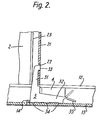
- Figure 2 is a sectional view through a joint between a beam and a support member.
- The joining element in Figure 1 is shaped as an
angular fastening bracket 3 with twowings wings 31 is provided with aprojection 33 which do-operates with agroove 22 inprofile wall 21 of thesupport member 2. Theother wing 32 has its outer surface, which turns towards an U-shapedchannel 11 in the beam 1, provided withrills 34. The rills run per- Dendicular to the corresponding rills which forms anarched bottom 13 of thechannel 11. The wing is terminated by abendable flap 35 which forms an integral part of thebracket 3. Other sections for the beam may also be used. - The
support member 2 is of hollow section having a substantially square cross-section and itsfront part 24 being located alongside the beam 1 in such way that the support member stops at right angle against two outward runningflanges 12 on the beam. The flanges make a combined support area for the support member and a lock plane against a wedge 4 which is used for fastening thebracket 3 to the beam. The section of thesupport member 2, is not critical and may for example, also be U-shaped. - The wings of the bracket are inserted in the support member and beam respectively. A suitable shape of the
wing 31 with a downward increasing cross-section secures the self- locking of the bracket in the support member when theprojection 33 is placed in thegroove 22. - Two guiding
flanges 23 inside thesupport members wall 21, which flanges run parallel to its longitudinal axis, facilitate insertion of the bracket and at the same time secure that the bracket is not pressed out of position during insertion of the wedge 4. The wedge locks the bracket'swing 32 in the beams U-shapedchannel 11 and the wedge itself is secured against sliding by theend flap 35 which is bent upward as indicated in Figure 2. - Figure 2 shows an alternative form of the
base 13 of the beam which is provided with aretaining projection 14. The retaining projection will further facilitate assembly in the case where the joining points have been determined in advance and further allows application of support members of simplified forms. - The invention is not confined to the above described embodiments. The support member which is shown in Figure 1 as a hollow profile can be replaced by other appropriate formed profile, e.g. an U-profile.
Claims (4)
Applications Claiming Priority (2)
| Application Number | Priority Date | Filing Date | Title |
|---|---|---|---|
| NO784009 | 1978-11-29 | ||
| NO784009A NO142229C (en) | 1978-11-29 | 1978-11-29 | PROFILE SYSTEM. |
Publications (2)
| Publication Number | Publication Date |
|---|---|
| EP0011992A1 EP0011992A1 (en) | 1980-06-11 |
| EP0011992B1 true EP0011992B1 (en) | 1983-01-26 |
Family
ID=19884560
Family Applications (1)
| Application Number | Title | Priority Date | Filing Date |
|---|---|---|---|
| EP79302673A Expired EP0011992B1 (en) | 1978-11-29 | 1979-11-22 | A profile system having support members and beams |
Country Status (4)
| Country | Link |
|---|---|
| US (1) | US4279529A (en) |
| EP (1) | EP0011992B1 (en) |
| DE (1) | DE2964649D1 (en) |
| NO (1) | NO142229C (en) |
Families Citing this family (10)
| Publication number | Priority date | Publication date | Assignee | Title |
|---|---|---|---|---|
| JPS60500678A (en) * | 1983-03-08 | 1985-05-09 | コスタンザ ピ−テイ−ワイ リミテツド | Structure of fence etc. |
| US4556564A (en) * | 1983-03-14 | 1985-12-03 | Ethyl Corporation | Feeding of zeolite A to poultry |
| DE3310005C2 (en) * | 1983-03-19 | 1985-10-24 | Heinz Georg Hünibach Thun Baus | Connection of two profile rails |
| US4609185A (en) * | 1984-06-25 | 1986-09-02 | Southwest Metals, Inc. | Fence structure and method for installation |
| FR2677084B1 (en) * | 1991-05-30 | 1993-09-10 | Legrand Sa | ASSEMBLY DEVICE FOR HOLLOW PROFILES. |
| DE4211796C2 (en) * | 1991-06-29 | 1994-10-20 | Manfred Neu | Device for connecting and locking two elements |
| US6061991A (en) * | 1997-10-15 | 2000-05-16 | Dahl; Michael E. | Deck system |
| DE10161190A1 (en) * | 2001-12-13 | 2003-06-18 | Fischer Artur Werke Gmbh | Node connector for mounting mounting rails |
| US7597771B2 (en) * | 2006-02-07 | 2009-10-06 | Comfort Line Ltd. | Pultrusion method and related article |
| USD599915S1 (en) * | 2007-11-26 | 2009-09-08 | Jerith Manufacturing Company, Inc. | Surface mount |
Family Cites Families (10)
| Publication number | Priority date | Publication date | Assignee | Title |
|---|---|---|---|---|
| DE932876C (en) * | 1952-05-09 | 1955-09-12 | Ver Deutsche Metallwerke Ag | Process for producing clamping connections between hollow bodies |
| DE1196429B (en) * | 1958-04-19 | 1965-07-08 | Ulrich Grajecki Dipl Ing | Corner connection for hollow profiles |
| US3294429A (en) * | 1964-03-30 | 1966-12-27 | Nickolas J Halip | Display board assembly and parts thereof |
| GB1195369A (en) * | 1966-12-08 | 1970-06-17 | Engineering Developments Birmi | Improvements in, or relating to, Couplings for Tubes, Bars and the like |
| US3498589A (en) * | 1967-08-30 | 1970-03-03 | Railtec Corp | Interlocking railing construction |
| ES157343Y (en) * | 1967-10-25 | 1971-05-16 | Societe Metallurgique De Saint-Louis | ANGLE ASSEMBLY ARRANGEMENT FOR METALLIC CARPENTRY. |
| BE721732A (en) | 1968-10-02 | 1969-03-14 | ||
| DE7522584U (en) * | 1974-07-23 | 1976-02-12 | Reynolds Aluminium Europe, En Abrege Aleurope S.A., Ghlin (Belgien) | Set of components for the assembly of metal structures with connection arrangement |
| US4050828A (en) * | 1975-03-19 | 1977-09-27 | Tadaomi Noro | Method of interlocking a lateral member and the end of a hollow post and the joint construction used therein |
| FR2323908A1 (en) * | 1975-09-11 | 1977-04-08 | Alsthom Cgee | Fan blade root locking - using taper headed bolt bearing on rod in radial hole communicating with root slot |
-
1978
- 1978-11-29 NO NO784009A patent/NO142229C/en unknown
-
1979
- 1979-11-21 US US06/096,558 patent/US4279529A/en not_active Expired - Lifetime
- 1979-11-22 EP EP79302673A patent/EP0011992B1/en not_active Expired
- 1979-11-22 DE DE7979302673T patent/DE2964649D1/en not_active Expired
Also Published As
| Publication number | Publication date |
|---|---|
| US4279529A (en) | 1981-07-21 |
| NO142229C (en) | 1980-07-16 |
| EP0011992A1 (en) | 1980-06-11 |
| NO142229B (en) | 1980-04-08 |
| DE2964649D1 (en) | 1983-03-03 |
| NO784009L (en) | 1980-04-08 |
Similar Documents
| Publication | Publication Date | Title |
|---|---|---|
| US3266210A (en) | Mullion and rail composite curtain wall construction | |
| US4408427A (en) | Framing system for demountable walls or the like | |
| US5943838A (en) | Metal stud with bendable tab channel support | |
| US4873805A (en) | Connecting means of curtainwall supporting mullions | |
| GB2176217A (en) | Interconnecting mullions and transoms of curtain walls | |
| IE54567B1 (en) | Demountable partitioning system | |
| EP0695847B1 (en) | Set of composite metal-wood sections for door- and window-frames | |
| EP0011992A1 (en) | A profile system having support members and beams | |
| EP1310612B1 (en) | Supporting structure for wall facing plates in building | |
| US3601946A (en) | Interlocking mullion construction | |
| US4896613A (en) | Composite bombardment inhibiting section for frame members | |
| IE920972A1 (en) | Partition frame structure | |
| EP0599846A1 (en) | COUPLING ELEMENT FOR PROFILE COMPOSITE ELEMENTS FOR DOORS OR WINDOWS. | |
| EP0361281B1 (en) | Angle joint piece | |
| US3363392A (en) | Adjustable stud anchor | |
| EP0491010A1 (en) | A method for joining two structural members by the aid of an adjustable fastener, and a mounting for use with said method. | |
| US4600330A (en) | Frame, more particularly for a shower partition | |
| EP0890698B1 (en) | A building facade member and a set of fittings for external mounting in an opening in a building facade and a method of mounting such a facade member | |
| JPS628253Y2 (en) | ||
| GB1559731A (en) | Grating assembly | |
| GB2195675A (en) | A ridge unit for glazed structures | |
| JPH0620829Y2 (en) | Outer wall | |
| JPH046461Y2 (en) | ||
| JPH0542183Y2 (en) | ||
| JPH0225902Y2 (en) |
Legal Events
| Date | Code | Title | Description |
|---|---|---|---|
| PUAI | Public reference made under article 153(3) epc to a published international application that has entered the european phase |
Free format text: ORIGINAL CODE: 0009012 |
|
| AK | Designated contracting states |
Designated state(s): CH DE FR GB SE |
|
| 17P | Request for examination filed |
Effective date: 19801004 |
|
| GRAA | (expected) grant |
Free format text: ORIGINAL CODE: 0009210 |
|
| AK | Designated contracting states |
Designated state(s): CH DE FR GB SE |
|
| REF | Corresponds to: |
Ref document number: 2964649 Country of ref document: DE Date of ref document: 19830303 |
|
| ET | Fr: translation filed | ||
| PGFP | Annual fee paid to national office [announced via postgrant information from national office to epo] |
Ref country code: SE Payment date: 19840930 Year of fee payment: 6 |
|
| PGFP | Annual fee paid to national office [announced via postgrant information from national office to epo] |
Ref country code: FR Payment date: 19841026 Year of fee payment: 6 |
|
| PGFP | Annual fee paid to national office [announced via postgrant information from national office to epo] |
Ref country code: CH Payment date: 19841126 Year of fee payment: 6 |
|
| PGFP | Annual fee paid to national office [announced via postgrant information from national office to epo] |
Ref country code: DE Payment date: 19841129 Year of fee payment: 6 |
|
| PG25 | Lapsed in a contracting state [announced via postgrant information from national office to epo] |
Ref country code: GB Effective date: 19881122 |
|
| PG25 | Lapsed in a contracting state [announced via postgrant information from national office to epo] |
Ref country code: SE Effective date: 19881123 |
|
| PG25 | Lapsed in a contracting state [announced via postgrant information from national office to epo] |
Ref country code: CH Effective date: 19881130 |
|
| GBPC | Gb: european patent ceased through non-payment of renewal fee | ||
| PG25 | Lapsed in a contracting state [announced via postgrant information from national office to epo] |
Ref country code: FR Free format text: LAPSE BECAUSE OF NON-PAYMENT OF DUE FEES Effective date: 19890731 |
|
| REG | Reference to a national code |
Ref country code: CH Ref legal event code: PL |
|
| PG25 | Lapsed in a contracting state [announced via postgrant information from national office to epo] |
Ref country code: DE Effective date: 19890801 |
|
| REG | Reference to a national code |
Ref country code: FR Ref legal event code: ST |
|
| EUG | Se: european patent has lapsed |
Ref document number: 79302673.3 Effective date: 19890726 |
|
| PLBE | No opposition filed within time limit |
Free format text: ORIGINAL CODE: 0009261 |
|
| STAA | Information on the status of an ep patent application or granted ep patent |
Free format text: STATUS: NO OPPOSITION FILED WITHIN TIME LIMIT |