EP0009398A1 - Thread structure for percussion drill elements - Google Patents
Thread structure for percussion drill elements Download PDFInfo
- Publication number
- EP0009398A1 EP0009398A1 EP79301941A EP79301941A EP0009398A1 EP 0009398 A1 EP0009398 A1 EP 0009398A1 EP 79301941 A EP79301941 A EP 79301941A EP 79301941 A EP79301941 A EP 79301941A EP 0009398 A1 EP0009398 A1 EP 0009398A1
- Authority
- EP
- European Patent Office
- Prior art keywords
- abutting
- flanks
- thread
- angle
- flank
- Prior art date
- Legal status (The legal status is an assumption and is not a legal conclusion. Google has not performed a legal analysis and makes no representation as to the accuracy of the status listed.)
- Granted
Links
- 238000009527 percussion Methods 0.000 title claims abstract description 9
- 230000008878 coupling Effects 0.000 claims abstract description 32
- 238000010168 coupling process Methods 0.000 claims abstract description 32
- 238000005859 coupling reaction Methods 0.000 claims abstract description 32
- 238000005553 drilling Methods 0.000 description 10
- 230000007423 decrease Effects 0.000 description 5
- 238000000034 method Methods 0.000 description 3
- 230000000694 effects Effects 0.000 description 2
- 239000000463 material Substances 0.000 description 2
- 238000005255 carburizing Methods 0.000 description 1
- 230000003247 decreasing effect Effects 0.000 description 1
- 238000003754 machining Methods 0.000 description 1
- 239000002184 metal Substances 0.000 description 1
- 238000000926 separation method Methods 0.000 description 1
Images

Classifications
-
- F—MECHANICAL ENGINEERING; LIGHTING; HEATING; WEAPONS; BLASTING
- F16—ENGINEERING ELEMENTS AND UNITS; GENERAL MEASURES FOR PRODUCING AND MAINTAINING EFFECTIVE FUNCTIONING OF MACHINES OR INSTALLATIONS; THERMAL INSULATION IN GENERAL
- F16B—DEVICES FOR FASTENING OR SECURING CONSTRUCTIONAL ELEMENTS OR MACHINE PARTS TOGETHER, e.g. NAILS, BOLTS, CIRCLIPS, CLAMPS, CLIPS OR WEDGES; JOINTS OR JOINTING
- F16B33/00—Features common to bolt and nut
- F16B33/02—Shape of thread; Special thread-forms
-
- E—FIXED CONSTRUCTIONS
- E21—EARTH OR ROCK DRILLING; MINING
- E21B—EARTH OR ROCK DRILLING; OBTAINING OIL, GAS, WATER, SOLUBLE OR MELTABLE MATERIALS OR A SLURRY OF MINERALS FROM WELLS
- E21B17/00—Drilling rods or pipes; Flexible drill strings; Kellies; Drill collars; Sucker rods; Cables; Casings; Tubings
- E21B17/02—Couplings; joints
- E21B17/04—Couplings; joints between rod or the like and bit or between rod and rod or the like
- E21B17/042—Threaded
- E21B17/0426—Threaded with a threaded cylindrical portion, e.g. for percussion rods
-
- Y—GENERAL TAGGING OF NEW TECHNOLOGICAL DEVELOPMENTS; GENERAL TAGGING OF CROSS-SECTIONAL TECHNOLOGIES SPANNING OVER SEVERAL SECTIONS OF THE IPC; TECHNICAL SUBJECTS COVERED BY FORMER USPC CROSS-REFERENCE ART COLLECTIONS [XRACs] AND DIGESTS
- Y10—TECHNICAL SUBJECTS COVERED BY FORMER USPC
- Y10T—TECHNICAL SUBJECTS COVERED BY FORMER US CLASSIFICATION
- Y10T403/00—Joints and connections
- Y10T403/57—Distinct end coupler
- Y10T403/5741—Separate screw or pin-type connections
-
- Y—GENERAL TAGGING OF NEW TECHNOLOGICAL DEVELOPMENTS; GENERAL TAGGING OF CROSS-SECTIONAL TECHNOLOGIES SPANNING OVER SEVERAL SECTIONS OF THE IPC; TECHNICAL SUBJECTS COVERED BY FORMER USPC CROSS-REFERENCE ART COLLECTIONS [XRACs] AND DIGESTS
- Y10—TECHNICAL SUBJECTS COVERED BY FORMER USPC
- Y10T—TECHNICAL SUBJECTS COVERED BY FORMER US CLASSIFICATION
- Y10T403/00—Joints and connections
- Y10T403/57—Distinct end coupler
- Y10T403/5746—Continuous thread
Definitions
- THIS invention relates to thread structures and more particularly to a cylindrical thread structure for use on percussion drilling parts, such as drill strings, which are also rotated.
- Such thread structures must provide a firm connection between the elements so that drill rods are not lost down holes and provide a sufficiently tight joint to transfer the drilling impact from rod-striker face to butting rod striker face with best possible efficiency while at the same time should allow the thread to be unscrewed easily.
- Percussion drilling methods have developed the need for more powerful drilling machines with the resulting higher drilling torque.
- Many drill units especially of the percussion variety, utilise threaded connections between the drill rod elements which consist of two or more aligned drill rods with a coupling sleeve. Many drilling methods effect a tightening of the threaded drill elements during use, especially in percussion drilling operations.
- the torque required for separation of the elements should not be too large for stripping, that is be toodifficult to separate the elements after a'high torque application which has been applied simultaneously with a percussive load.
- a further problem with such coupling threads is that they must have an acceptable wearing life.
- the uncoupling torque and coupling torque are usually related to each other and among other things depend on the materials used, hardness of the contacting thread surfaces, the angle of the abutting threads and the pitch of the thread. In general the uncoupling torque increases as the pitch and flank angles decrease.
- Reissue patent 27,284 proposes a thread structure to minimise uncoupling torque when the threads have symmetrical abutting and secondary flanks which are arcuate and have a maximum flank angle with respect to the drill rod axes adjacent the rod thread crests in the range 45 - 20° and preferably 40° - 30° which decreases to zero at the bottom of the thread, has two or more starts and, consequently, has a pitch or lead angle of 5 - 14°, preferably 7 - 11°, and the crests of the threads are substantially flat.
- these straight crests ensure that the contact between the matching thread surfaces adjacent the crests of the rod thread is established only at portions of the thread having an angle of inclination to the axis which is substantially different from 0 0 so that wedging does not occur. It is believed that because of the use of two or more starts whereby a greater pitch angle can be employed than was usual at the date of invention of that patent some decrease of the uncoupling torque could be obtained. However, it seems that the varying flank angles counteracts this effect to some extent. Also it is believed that the wear life of the coupling was not improved because of the thread profile which does not maximise the area of the contacting surfaces or minimise the contact pressures.
- the thread profile does not make full use of the hardened surfaces of the coupling structure, which is usually 0,7 to 1,4 mm thick and much wear would take place in the relatively softer, un-hardened material of the coupling.
- the thread structure does not allow for the weight of the coupling sleeve to be decreased even though it is known that the wear rate increases as the weight of the coupling sleeve increases.
- This invention seeks to provide a coupling structure which will satisfactorily meet the wearing life requirements of a user while at the same time have acceptable unlocking torque characteristics.
- the invention provides a coupling thread structure for percussion drill elements including a rod having an external thread and a sleeve having an internal thread with the threads, when the rod and sleeve are coupled together, presenting abutting and non-abutting flanks, with the flanks being joined by crest and bottom portions and with.
- a coupling thread structure for percussion drill elements including a rod having an external thread and a sleeve having an internal thread with the threads, when the rod and sleeve are coupled together, presenting abutting and non-abutting flanks, with the flanks being joined by crest and bottom portions and with.
- the thread structure of this invention has an abutting flank angle much smaller than and a pitch angle which is much greater than currently used thread structures or disclosed prior art structures.
- this larger pitch angle with a smaller flank angle results in an increased flank contact area which in turn produces a reduced pressure on the abutting flank contact areas so yielding a slower wear rate during drilling.
- the larger pitch angle and the smaller flank angle ensure that the unlocking torque is acceptable, and of the same order or less than currently available thread structures, while at the same time providing the desired self-locking characteristics which ensure that the drill string does not become unintentionally uncoupled during use.
- a coupling thread structure for percussion drill elements including a rod having an external thread and a sleeve having an internal thread with the threads, when the sleeve and rod are coupled, having abutting and non-abutting flanks 4 nd with the flanks being joined by bottom and crest portions, wherein the threads have at least two starts or entrances; the abutting flanks are substantially straight along their whole abutting contact portions and form an angle of between about 10° and 25 0 with the drill axis; the pitch or lead angle of the threads is in the range 9 to 20°; the crest portions are substantially straight and intersect the abutting flank portions at a well defined edge; the non-abutting flanks have a flank angle which is considerably greater than that of the abutting flanks; and the flank angle of the non-abutting flanks is in the range 50 to 80° with respect to the drill axis.
- the non-abutting flanks have a flank angle in the range 65 to 75°.
- the wear depth is 2,5 mm which is comparatively large. If a carburizing and hardening process is used for making the threads, the case depth normally is 1,0 to 1,4 mm and when compared with the wear depth of 2,5 mm one can see that the latter part of the wear life will be spent in the softer core with a relatively higher wear rate.
- the wear depth with the thread structure of the invention is only 0,73 mm with the design given above; thus the whole wear life is spent inside the effective case hardened zone which should give a much slower wear rate.
- An added feature in this case is the lesser deformation of the wear surfaces during the surface life of the thread structure which means better matching when components at different stages of wear are used together.
- an advantage of the new thread structure of the invention is that the wear life, which is very much related to the flank surface loading, can be selected to match the rod fatigue life, while still maintaining the desired locking and unlocking properties.
- the thread wear life should not be increased into the range of the rod fatigue life so that in a proper design the rod can be discarded after a pre-selected amount of wear of the thread structure which will occur before the rod reaches the end of its life. In other words the rod should not break in service.
- the use of a relatively large flank angle for the non-abutting flank 18 provides a number of advantages. One is that it permits the pitch to be varied as desired within a broad range of pitch and flank angles. Another is that it decreases the volume of metal actually involved in the threads so that the weight of the coupling can be reduced. The use of this large non-abutting flank angle does not decrease the strength of the coupling in any way since with the relatively small abutting flank angle most of the forces on the threads are radial and not axial. Also, since the non-abutting flank plays no part in the coupling,the fit or guidance of the sleeve on the rod is unaffected. Another feature of this relatively larger flank is that it assists in visually distinguishing the thread structure of the invention from other thread structures which may happen to be in use at the same location.
Landscapes
- Engineering & Computer Science (AREA)
- General Engineering & Computer Science (AREA)
- Mechanical Engineering (AREA)
- Mining & Mineral Resources (AREA)
- Life Sciences & Earth Sciences (AREA)
- Geology (AREA)
- Fluid Mechanics (AREA)
- Environmental & Geological Engineering (AREA)
- Physics & Mathematics (AREA)
- General Life Sciences & Earth Sciences (AREA)
- Geochemistry & Mineralogy (AREA)
- Earth Drilling (AREA)
- Drilling And Exploitation, And Mining Machines And Methods (AREA)
- Electrophonic Musical Instruments (AREA)
Abstract
Description
- THIS invention relates to thread structures and more particularly to a cylindrical thread structure for use on percussion drilling parts, such as drill strings, which are also rotated.
- Such thread structures must provide a firm connection between the elements so that drill rods are not lost down holes and provide a sufficiently tight joint to transfer the drilling impact from rod-striker face to butting rod striker face with best possible efficiency while at the same time should allow the thread to be unscrewed easily. Percussion drilling methods have developed the need for more powerful drilling machines with the resulting higher drilling torque. Many drill units, especially of the percussion variety, utilise threaded connections between the drill rod elements which consist of two or more aligned drill rods with a coupling sleeve. Many drilling methods effect a tightening of the threaded drill elements during use, especially in percussion drilling operations. The torque required for separation of the elements should not be too large for stripping, that is be toodifficult to separate the elements after a'high torque application which has been applied simultaneously with a percussive load. A further problem with such coupling threads is that they must have an acceptable wearing life.
- The uncoupling torque and coupling torque are usually related to each other and among other things depend on the materials used, hardness of the contacting thread surfaces, the angle of the abutting threads and the pitch of the thread. In general the uncoupling torque increases as the pitch and flank angles decrease. U.S. Reissue patent 27,284 proposes a thread structure to minimise uncoupling torque when the threads have symmetrical abutting and secondary flanks which are arcuate and have a maximum flank angle with respect to the drill rod axes adjacent the rod thread crests in the range 45 - 20° and preferably 40° - 30° which decreases to zero at the bottom of the thread, has two or more starts and, consequently, has a pitch or lead angle of 5 - 14°, preferably 7 - 11°, and the crests of the threads are substantially flat. According to the patent these straight crests ensure that the contact between the matching thread surfaces adjacent the crests of the rod thread is established only at portions of the thread having an angle of inclination to the axis which is substantially different from 00 so that wedging does not occur. It is believed that because of the use of two or more starts whereby a greater pitch angle can be employed than was usual at the date of invention of that patent some decrease of the uncoupling torque could be obtained. However, it seems that the varying flank angles counteracts this effect to some extent. Also it is believed that the wear life of the coupling was not improved because of the thread profile which does not maximise the area of the contacting surfaces or minimise the contact pressures. Also the thread profile does not make full use of the hardened surfaces of the coupling structure, which is usually 0,7 to 1,4 mm thick and much wear would take place in the relatively softer, un-hardened material of the coupling. Finally, the thread structure does not allow for the weight of the coupling sleeve to be decreased even though it is known that the wear rate increases as the weight of the coupling sleeve increases.
- This invention seeks to provide a coupling structure which will satisfactorily meet the wearing life requirements of a user while at the same time have acceptable unlocking torque characteristics.
- The invention provides a coupling thread structure for percussion drill elements including a rod having an external thread and a sleeve having an internal thread with the threads, when the rod and sleeve are coupled together, presenting abutting and non-abutting flanks, with the flanks being joined by crest and bottom portions and with. the following chacacter- istics:
- the thread has at least two starts or entrances;
- the abutting flanks are straight along their whole abutting contact portions;
- the abutting flank portions form an angle or between 10° and 25° with the drill axis; and
- the pitch angle of the threads is between 9° and 200.
- Currently available thread structures of this type normally have an abutting flank angle of between 25° and 40° with the drill axis and a pitch angle for the threads normally between about 5° and 110, the higher pitch angles being used with two start threads, e.g. as especially mentioned in U.S. Reissue 27,284. Thus it can be seen that the thread structure of this invention has an abutting flank angle much smaller than and a pitch angle which is much greater than currently used thread structures or disclosed prior art structures. As discussed below this larger pitch angle with a smaller flank angle results in an increased flank contact area which in turn produces a reduced pressure on the abutting flank contact areas so yielding a slower wear rate during drilling. At the same time the larger pitch angle and the smaller flank angle ensure that the unlocking torque is acceptable, and of the same order or less than currently available thread structures, while at the same time providing the desired self-locking characteristics which ensure that the drill string does not become unintentionally uncoupled during use.
- Further features of the invention are that:
- The angle which the abutting flank portions form with the drill axis are preferably between 15° and 25° and preferably less than 20°;
- the pitch angle is preferably between 9° and 16° and preferably greater than 11°;
- The crest portions are straight and, conveniently, parallel to the drill axis though they may be inclined to the drill axis slightly, such as up to about 3°, in a direction from the abutting to non-abutting flanks;
- At least one of, and preferably both of, the abutting and non-abutting flank portions intersect the crest portions at a well defined edge to facilitate machining;
- The bottom portions are curved, preferably merge tangentially with the abutting and non-abutting flank portions, and have a radius of curvature which is greater than the depth of the thread, i.e. the radial distance between the crest portion and base of the bottom portion; and
- The internal and external threads i.e. on the coupling sleeve and drill rod are substantially similar, while being reflections of each other in one form. In another fornl of the invention the crest portion is made relatively longer on the rod than on the coupling i.e. height of crest portion of the thread on the rod from the drill axis,is less than the distance of the bottom portion of the thread on the coupling sleeve from the drill axis, so that the rod thread wear life will be greater than that of the coupling thread life.
- According to the invention there is also provided a coupling thread structure for percussion drill elements including a rod having an external thread and a sleeve having an internal thread with the threads, when the sleeve and rod are coupled, having abutting and non-abutting flanks 4nd with the flanks being joined by bottom and crest portions, wherein the threads have at least two starts or entrances; the abutting flanks are substantially straight along their whole abutting contact portions and form an angle of between about 10° and 250 with the drill axis; the pitch or lead angle of the threads is in the range 9 to 20°; the crest portions are substantially straight and intersect the abutting flank portions at a well defined edge; the non-abutting flanks have a flank angle which is considerably greater than that of the abutting flanks; and the flank angle of the non-abutting flanks is in the range 50 to 80° with respect to the drill axis.
- Preferably the non-abutting flanks have a flank angle in the range 65 to 75°.
- Further features and advantages of the invention will become apparent from the following description made with reference to the accompanying drawings.
-
- Figure 1 shows a portion of a drill rod formed with a thread according to the invention;
- Figure.2 shows a coupling sleeve also formed with a thread of the invention for engaging the drill rod of Figure 1;
- Figure 3 shows, on an enlarged scale, a section through a portion of the coupling sleeve of Figure 2 illustrating the thread profile in greater detail;
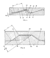
- Figure 4 shows a section through a part of a coupling thread structure of the invention; and
- Figure 5 shows a section similar to that of Figure 4, but of a prior art coupling thread structure.
-
- Figure 1 shows a portion of a
drill rod 10 having athread structure 12 according to the invention at its end. Thethread structure 12 is in the form of an enlarged diameter portion of the rod formed with a two-entrance or two-start thread 14. As will be described in greater detail below the thread has anabutting flank portion 16, anon-abutting flank portion 18, acrest 20, and abottom portion 22. - Figure 2 shows a
coupling sleeve 24 engageable with the threadedportion 12 of therod 10 and formed withinternal threads 26. Theinternal threads 26 are similar in profile to thethreads 14 of the drill rod but are reflections of those threads. - Figure 3 shows the
threads 26 of thecoupling sleeve 24 in more detail, For ease of reference the same or similar parts as those in Figure 1 have the same reference numerals. As can be seen the thread has a straight abuttingflank portion 16 which merges tangentially with thecurved bottom portion 22, which, in turn, merges with thenon-abutting flank portion 18 that has astraight portion 19 at its radially inner end. Thestraight portion 19 meets thecrest portion 22 at a welldefined edge 28. Thecrest portion 20, which is straight and parallel to the drill axis, also meets the nextabutting flank portion 16 at a well definededge 30. As shown thebottom portion 22 is curved with the radius of curvature R being greater than the depth of the bottom portion, i.e. the radial distance between thecrest portion 20 and the bottom of thecurved portion 22. In this example theabutting flank 16 makes an angle of 18,5 with the drill axis. Thestraight portion 19 of thenon-abutting flank 18 forms an angle of 71,50 with the drill axis. - Figure 4 shows the
rod thread portion 14 and the couplingsleeve thread portion 26 engaged with one another. As can be clearly seen there is a clearance formed between therespective crest portions 20 andbottom portions 22. Theabutting flanks 16 are shown contacting one another, while thenon-abutting flanks 18 are spaced from one another. The length, measured along the abutting flank, of the contact between theabutting flanks 16 is denoted "CL". Also shown is ahatched region 32 which represents the developed form of the thread after it has worn in service. - Figure 5 shows a prior art coupling structure in which the same reference numerals as used previously are used, but with the prefix 100. The contact length "CL" of the abutting
flanks 116 and the wear depth "WD" of the thread in service are also shown as was done in Figure 4. - Below is a table giving a comparison for a 38 mm coupling thread between a prior arε thread and a thread made according to the invention.

- From the table above it will be appreciated that the following features emerge.
- Firstly with the thread structure of the invention there is a reduced pressure in the abutting flank surface contact area. This reduced pressure will result in a slower wear rate during drilling compared with the prior art structure. The relation between surface pressure and wear rate is not known, but judging from experience, the wear rate should be retarded more than the proportional difference.
- Secondly with the prior art thread structure, the wear depth is 2,5 mm which is comparatively large. If a carburizing and hardening process is used for making the threads, the case depth normally is 1,0 to 1,4 mm and when compared with the wear depth of 2,5 mm one can see that the latter part of the wear life will be spent in the softer core with a relatively higher wear rate. On the other hand the wear depth with the thread structure of the invention is only 0,73 mm with the design given above; thus the whole wear life is spent inside the effective case hardened zone which should give a much slower wear rate. An added feature in this case is the lesser deformation of the wear surfaces during the surface life of the thread structure which means better matching when components at different stages of wear are used together.
- Thirdly as will be appreciated by persons skilled in the art, the thread structure of the invention will not loosen during drilling, while at the same time the coupling would still be satisfactorily easy to uncouple when desired.
- Fourthly, an advantage of the new thread structure of the invention is that the wear life, which is very much related to the flank surface loading, can be selected to match the rod fatigue life, while still maintaining the desired locking and unlocking properties. In practice the thread wear life should not be increased into the range of the rod fatigue life so that in a proper design the rod can be discarded after a pre-selected amount of wear of the thread structure which will occur before the rod reaches the end of its life. In other words the rod should not break in service.
- Finally, the use of a relatively large flank angle for the
non-abutting flank 18 provides a number of advantages. One is that it permits the pitch to be varied as desired within a broad range of pitch and flank angles. Another is that it decreases the volume of metal actually involved in the threads so that the weight of the coupling can be reduced. The use of this large non-abutting flank angle does not decrease the strength of the coupling in any way since with the relatively small abutting flank angle most of the forces on the threads are radial and not axial. Also, since the non-abutting flank plays no part in the coupling,the fit or guidance of the sleeve on the rod is unaffected. Another feature of this relatively larger flank is that it assists in visually distinguishing the thread structure of the invention from other thread structures which may happen to be in use at the same location. - As will be appreciated by persons skilled in the art many changes may be made to the thread structure of the invention without departing from the spirit or principles of this invention. For example, the precise angles for the pitch and flanks can be varied. Also the nominal rod diameter can be chosen as desired. Also the thread structure can be used between a drill rod and a drill bit. Accordingly, the embodiment specifically described above with reference to the drawings is to be regarded as illustrative and not limiting.
Claims (17)
Priority Applications (1)
| Application Number | Priority Date | Filing Date | Title |
|---|---|---|---|
| AT79301941T ATE6536T1 (en) | 1978-09-21 | 1979-09-18 | THREAD FOR IMPACT ROD CONNECTOR. |
Applications Claiming Priority (2)
| Application Number | Priority Date | Filing Date | Title |
|---|---|---|---|
| ZA785370 | 1978-09-21 | ||
| ZA00785370A ZA785370B (en) | 1978-09-21 | 1978-09-21 | Thread structure for percussion drill elements |
Publications (2)
| Publication Number | Publication Date |
|---|---|
| EP0009398A1 true EP0009398A1 (en) | 1980-04-02 |
| EP0009398B1 EP0009398B1 (en) | 1984-03-07 |
Family
ID=25573442
Family Applications (1)
| Application Number | Title | Priority Date | Filing Date |
|---|---|---|---|
| EP79301941A Expired EP0009398B1 (en) | 1978-09-21 | 1979-09-18 | Thread structure for percussion drill elements |
Country Status (8)
| Country | Link |
|---|---|
| US (1) | US4295751A (en) |
| EP (1) | EP0009398B1 (en) |
| AT (1) | ATE6536T1 (en) |
| AU (1) | AU524612B2 (en) |
| CA (1) | CA1122424A (en) |
| DE (1) | DE2966756D1 (en) |
| IE (1) | IE48832B1 (en) |
| ZA (1) | ZA785370B (en) |
Cited By (9)
| Publication number | Priority date | Publication date | Assignee | Title |
|---|---|---|---|---|
| EP0198809A3 (en) * | 1985-04-16 | 1988-08-31 | Atlas Copco Aktiebolag | Rock drilling device and a drill stem for said device |
| EP0253789A3 (en) * | 1986-07-15 | 1989-03-22 | Sandvik Aktiebolag | Threaded coupling for percussion drill rods threaded coupling for percussion drill rods |
| EP0324442A1 (en) * | 1988-01-11 | 1989-07-19 | Sandvik Rock Tools Inc. | Elliptical thread design |
| GB2227802A (en) * | 1989-01-26 | 1990-08-08 | Square Grip Ltd | Concrete reinforcement bar couplings and apparatus for enlarging bar ends |
| EP0520198A1 (en) * | 1991-06-28 | 1992-12-30 | Bowen Tools, Inc. | Round threadform for marine riser top joint |
| WO2001069621A1 (en) | 2000-03-16 | 2001-09-20 | Naimer H L | Switch |
| WO2008124855A2 (en) | 2007-04-13 | 2008-10-23 | 'alwag' Tunnelausbau Gesellschaft M.B.H. | Method and device for securing an externally threaded object against being unscrewed |
| WO2010085829A2 (en) | 2009-01-27 | 2010-08-05 | Dywidag-Systems International Gmbh | Device for coupling two tubular elements |
| EP3536893A1 (en) | 2018-03-09 | 2019-09-11 | Sandvik Mining and Construction Tools AB | Connection for percussion drilling |
Families Citing this family (30)
| Publication number | Priority date | Publication date | Assignee | Title |
|---|---|---|---|---|
| US4549754A (en) * | 1983-06-20 | 1985-10-29 | Reed Tubular Products Company | Tool joint |
| SE459681B (en) * | 1985-01-07 | 1989-07-24 | Santrade Ltd | DRILLING ELEMENT BEFORE SHOCK DRILLING |
| SE469602B (en) * | 1985-04-04 | 1993-08-02 | Sandvik Ab | CUTTING HEAD BEFORE SHOCK DRILLING |
| SE460301B (en) * | 1986-10-15 | 1989-09-25 | Sandvik Ab | CUTTING ROD FOR STOCKING DRILLING MACHINE |
| US4865364A (en) * | 1988-07-05 | 1989-09-12 | Vetco Gray Inc. | Conical thread form |
| US5127784A (en) * | 1989-04-19 | 1992-07-07 | Halliburton Company | Fatigue-resistant buttress thread |
| US5060740A (en) * | 1990-05-29 | 1991-10-29 | Sandvik Rock Tools, Inc. | Screw thread coupling |
| US5163523A (en) * | 1990-05-29 | 1992-11-17 | Sandvik Rock Tools, Inc. | Screw thread structure for percussion drill driver sub and case |
| US5056611A (en) * | 1990-05-29 | 1991-10-15 | Galloway Trust | Screw thread structure |
| US5169256A (en) * | 1990-10-26 | 1992-12-08 | Woodings Industrial Corporation | Hand connect-disconnect coupling for blast furnace tap hole drill rod assembly |
| US5356236A (en) * | 1991-09-25 | 1994-10-18 | Turbomeca | Device for connecting two elements in rotation |
| US6074119A (en) * | 1996-10-01 | 2000-06-13 | Schlanger; Raphael | Connecting device including connectable members and tapered element |
| AUPO445897A0 (en) * | 1997-01-06 | 1997-01-30 | Boart Longyear Inc. | Straight hole drilling system |
| DE19803304C5 (en) * | 1997-05-29 | 2010-09-30 | Boart Longyear Gmbh & Co. Kg Hartmetallwerkzeugfabrik | Drill pipe for rotary impact drilling, in particular for overlay drilling |
| SE515518C2 (en) * | 1998-09-28 | 2001-08-20 | Uniroc Ab | String drill string thread for striking rock drilling |
| US6467818B1 (en) * | 1999-10-01 | 2002-10-22 | Grant Prideco, L.P. | Drill collar box |
| SE0000701L (en) * | 2000-03-02 | 2001-06-25 | Sandvik Ab | Threaded joints and rock drill elements for striking drilling |
| SE0000702L (en) * | 2000-03-02 | 2001-06-25 | Sandvik Ab | Threaded joints and rock drill elements for striking drilling |
| SE520077C2 (en) * | 2002-06-27 | 2003-05-20 | Sandvik Ab | Male part for percussion drilling of rock, has threaded end section with specific geometry adjacent to stop surface |
| KR100864105B1 (en) * | 2004-09-03 | 2008-10-16 | 라이스트리츠 아게 | Extruder screw, extruder and shaft-hub connection |
| US20100018699A1 (en) * | 2007-03-21 | 2010-01-28 | Hall David R | Low Stress Threadform with a Non-conic Section Curve |
| CA2634557C (en) * | 2008-05-07 | 2013-06-11 | Dover Corporation (Canada) Limited | Sucker rod |
| US9643264B2 (en) | 2013-07-25 | 2017-05-09 | Kennametal Inc. | Coupling mechanism for cutting tool |
| US9643262B2 (en) | 2013-07-25 | 2017-05-09 | Kennametal Inc. | Coupling mechanism for cutting tool |
| CN105431665A (en) * | 2013-07-31 | 2016-03-23 | 未来管道工业集团有限公司 | 4 thread thread profile |
| US9889509B2 (en) | 2014-05-05 | 2018-02-13 | Kennametal Inc. | Cutter heads with improved coupling |
| KR101505957B1 (en) * | 2014-05-09 | 2015-03-26 | 기언관 | Reinforcing rod a coupling device for hooped reinforcement |
| DE102016105342A1 (en) * | 2016-03-22 | 2017-09-28 | Benteler Steel/Tube Gmbh | OCTG piping system and process for producing an OCTG pipe |
| EP3536894B1 (en) * | 2018-03-09 | 2020-10-14 | Sandvik Mining and Construction Tools AB | Coupling for connecting downhole tubulars |
| AU2021221436A1 (en) * | 2021-05-04 | 2022-11-24 | Illinois Tool Works Inc. | Coupler for threaded reinforcing bar |
Citations (5)
| Publication number | Priority date | Publication date | Assignee | Title |
|---|---|---|---|---|
| DE2115935B (en) * | Sandvikens Jernverks Ab, Sandviken (Schweden) | Threaded connection for hammer drill rods connected by sleeves and adapter for connecting a drill bit | ||
| DE1173046B (en) * | 1958-12-30 | 1964-07-02 | Boehler & Co Ag Geb | Connection of the drill rods of percussion drills |
| DE1229945B (en) * | 1963-06-03 | 1966-12-08 | Gardner Denver Co | Tubular boring bar |
| GB1111995A (en) * | 1964-05-29 | 1968-05-01 | Sandvikens Jernverks Ab | Improvements in threaded drill rod elements |
| US4040756A (en) * | 1976-03-05 | 1977-08-09 | Trw Canada Limited | Drill rod thread form |
Family Cites Families (4)
| Publication number | Priority date | Publication date | Assignee | Title |
|---|---|---|---|---|
| SE336316B (en) * | 1969-10-22 | 1971-07-05 | Fagersta Bruks Ab | |
| SE401232B (en) * | 1970-05-04 | 1978-04-24 | Sandvik Ab | THREADED CONNECTION FOR IMPACT BRUSHES |
| US3822952A (en) * | 1971-01-07 | 1974-07-09 | Sandvik Ab | Drill rod coupling |
| DE7531174U (en) * | 1975-10-02 | 1977-03-24 | Robert Bosch Gmbh, 7000 Stuttgart | DEVICE FOR THE TRANSMISSION OF TORQUE TO IMPACT DRILLING TOOLS |
-
1978
- 1978-09-21 ZA ZA00785370A patent/ZA785370B/en unknown
-
1979
- 1979-09-18 AT AT79301941T patent/ATE6536T1/en active
- 1979-09-18 EP EP79301941A patent/EP0009398B1/en not_active Expired
- 1979-09-18 DE DE7979301941T patent/DE2966756D1/en not_active Expired
- 1979-09-18 IE IE1766/79A patent/IE48832B1/en unknown
- 1979-09-20 AU AU51032/79A patent/AU524612B2/en not_active Ceased
- 1979-09-20 CA CA336,031A patent/CA1122424A/en not_active Expired
- 1979-09-21 US US06/077,549 patent/US4295751A/en not_active Expired - Lifetime
Patent Citations (5)
| Publication number | Priority date | Publication date | Assignee | Title |
|---|---|---|---|---|
| DE2115935B (en) * | Sandvikens Jernverks Ab, Sandviken (Schweden) | Threaded connection for hammer drill rods connected by sleeves and adapter for connecting a drill bit | ||
| DE1173046B (en) * | 1958-12-30 | 1964-07-02 | Boehler & Co Ag Geb | Connection of the drill rods of percussion drills |
| DE1229945B (en) * | 1963-06-03 | 1966-12-08 | Gardner Denver Co | Tubular boring bar |
| GB1111995A (en) * | 1964-05-29 | 1968-05-01 | Sandvikens Jernverks Ab | Improvements in threaded drill rod elements |
| US4040756A (en) * | 1976-03-05 | 1977-08-09 | Trw Canada Limited | Drill rod thread form |
Cited By (10)
| Publication number | Priority date | Publication date | Assignee | Title |
|---|---|---|---|---|
| EP0198809A3 (en) * | 1985-04-16 | 1988-08-31 | Atlas Copco Aktiebolag | Rock drilling device and a drill stem for said device |
| EP0253789A3 (en) * | 1986-07-15 | 1989-03-22 | Sandvik Aktiebolag | Threaded coupling for percussion drill rods threaded coupling for percussion drill rods |
| EP0324442A1 (en) * | 1988-01-11 | 1989-07-19 | Sandvik Rock Tools Inc. | Elliptical thread design |
| GB2227802A (en) * | 1989-01-26 | 1990-08-08 | Square Grip Ltd | Concrete reinforcement bar couplings and apparatus for enlarging bar ends |
| EP0520198A1 (en) * | 1991-06-28 | 1992-12-30 | Bowen Tools, Inc. | Round threadform for marine riser top joint |
| WO2001069621A1 (en) | 2000-03-16 | 2001-09-20 | Naimer H L | Switch |
| WO2008124855A2 (en) | 2007-04-13 | 2008-10-23 | 'alwag' Tunnelausbau Gesellschaft M.B.H. | Method and device for securing an externally threaded object against being unscrewed |
| WO2010085829A2 (en) | 2009-01-27 | 2010-08-05 | Dywidag-Systems International Gmbh | Device for coupling two tubular elements |
| EP3536893A1 (en) | 2018-03-09 | 2019-09-11 | Sandvik Mining and Construction Tools AB | Connection for percussion drilling |
| WO2019170437A1 (en) | 2018-03-09 | 2019-09-12 | Sandvik Mining And Construction Tools Ab | Connection for percussion drilling |
Also Published As
| Publication number | Publication date |
|---|---|
| IE48832B1 (en) | 1985-05-29 |
| CA1122424A (en) | 1982-04-27 |
| ZA785370B (en) | 1979-11-28 |
| AU524612B2 (en) | 1982-09-23 |
| DE2966756D1 (en) | 1984-04-12 |
| ATE6536T1 (en) | 1984-03-15 |
| EP0009398B1 (en) | 1984-03-07 |
| AU5103279A (en) | 1980-03-27 |
| US4295751A (en) | 1981-10-20 |
| IE791766L (en) | 1980-03-21 |
Similar Documents
| Publication | Publication Date | Title |
|---|---|---|
| US4295751A (en) | Thread structure for percussion drill elements | |
| US5060740A (en) | Screw thread coupling | |
| US3388935A (en) | Threaded drill rod element | |
| US4076436A (en) | Stress relieved tool elements | |
| US6030004A (en) | High torque threaded tool joint for drill pipe and other drill stem components | |
| US12378984B2 (en) | Threaded and coupled tubular goods connection | |
| EP0324442B1 (en) | Elliptical thread design | |
| US20040026924A1 (en) | Thread design for uniform distribution of makeup forces | |
| JP2001524196A (en) | Super high torque double shoulder type tool fitting | |
| US5163523A (en) | Screw thread structure for percussion drill driver sub and case | |
| US12241313B2 (en) | Connection for percussion drilling | |
| US20240229567A9 (en) | Coupling for connecting downhole tubulars with reduced stress | |
| CA2652278A1 (en) | A top hammer rock-drilling tool, a drill rod and coupling sleeve | |
| US6293360B1 (en) | Thread joint percussive drilling equipment | |
| US3822952A (en) | Drill rod coupling | |
| FI86664C (en) | GAENGKOPPLING. | |
| US20240133245A1 (en) | Coupling for connecting downhole tubulars with improved stress distribution | |
| US5143411A (en) | Threaded tubular connection | |
| US5535837A (en) | Helical stress relief groove apparatus and method for subterranean well drill pipe assemblies | |
| CA1037730A (en) | Drill rod thread form | |
| OA21326A (en) | Coupling for connecting downhole tubulars with improved stress distribution. | |
| JP2000008760A (en) | Linear boring system | |
| OA21325A (en) | Coupling for connecting downhole tubulars with reduced stress. | |
| JP2002156077A (en) | Oil well pipe |
Legal Events
| Date | Code | Title | Description |
|---|---|---|---|
| PUAI | Public reference made under article 153(3) epc to a published international application that has entered the european phase |
Free format text: ORIGINAL CODE: 0009012 |
|
| AK | Designated contracting states |
Designated state(s): AT BE CH DE FR GB IT SE |
|
| 17P | Request for examination filed | ||
| ITF | It: translation for a ep patent filed | ||
| GRAA | (expected) grant |
Free format text: ORIGINAL CODE: 0009210 |
|
| AK | Designated contracting states |
Designated state(s): AT BE CH DE FR GB IT SE |
|
| REF | Corresponds to: |
Ref document number: 6536 Country of ref document: AT Date of ref document: 19840315 Kind code of ref document: T |
|
| REF | Corresponds to: |
Ref document number: 2966756 Country of ref document: DE Date of ref document: 19840412 |
|
| PGFP | Annual fee paid to national office [announced via postgrant information from national office to epo] |
Ref country code: DE Payment date: 19840502 Year of fee payment: 6 |
|
| PGFP | Annual fee paid to national office [announced via postgrant information from national office to epo] |
Ref country code: FR Payment date: 19840523 Year of fee payment: 6 |
|
| ET | Fr: translation filed | ||
| PGFP | Annual fee paid to national office [announced via postgrant information from national office to epo] |
Ref country code: BE Payment date: 19840630 Year of fee payment: 6 |
|
| PGFP | Annual fee paid to national office [announced via postgrant information from national office to epo] |
Ref country code: AT Payment date: 19840702 Year of fee payment: 6 |
|
| PGFP | Annual fee paid to national office [announced via postgrant information from national office to epo] |
Ref country code: CH Payment date: 19840927 Year of fee payment: 6 |
|
| PGFP | Annual fee paid to national office [announced via postgrant information from national office to epo] |
Ref country code: SE Payment date: 19840930 Year of fee payment: 6 |
|
| PLBI | Opposition filed |
Free format text: ORIGINAL CODE: 0009260 |
|
| 26 | Opposition filed |
Opponent name: SANDVIK AKTIEBOLAG Effective date: 19840929 |
|
| RDAG | Patent revoked |
Free format text: ORIGINAL CODE: 0009271 |
|
| STAA | Information on the status of an ep patent application or granted ep patent |
Free format text: STATUS: PATENT REVOKED |
|
| 27W | Patent revoked |
Effective date: 19850902 |
|
| REG | Reference to a national code |
Ref country code: CH Ref legal event code: PL |
|
| GBPR | Gb: patent revoked under art. 102 of the ep convention designating the uk as contracting state | ||
| REG | Reference to a national code |
Ref country code: FR Ref legal event code: ST |
|
| BERE | Be: lapsed |
Owner name: BOART INTERNATIONAL LTD Effective date: 19860930 |
|
| EUG | Se: european patent has lapsed |
Ref document number: 79301941.5 Effective date: 19860729 |