EP0008148B1 - Self priming passive dosing dispenser - Google Patents
Self priming passive dosing dispenser Download PDFInfo
- Publication number
- EP0008148B1 EP0008148B1 EP79200430A EP79200430A EP0008148B1 EP 0008148 B1 EP0008148 B1 EP 0008148B1 EP 79200430 A EP79200430 A EP 79200430A EP 79200430 A EP79200430 A EP 79200430A EP 0008148 B1 EP0008148 B1 EP 0008148B1
- Authority
- EP
- European Patent Office
- Prior art keywords
- liquid
- inlet port
- dispenser
- reservoir
- impervious
- Prior art date
- Legal status (The legal status is an assumption and is not a legal conclusion. Google has not performed a legal analysis and makes no representation as to the accuracy of the status listed.)
- Expired
Links
Images




Classifications
-
- E—FIXED CONSTRUCTIONS
- E03—WATER SUPPLY; SEWERAGE
- E03D—WATER-CLOSETS OR URINALS WITH FLUSHING DEVICES; FLUSHING VALVES THEREFOR
- E03D9/00—Sanitary or other accessories for lavatories ; Devices for cleaning or disinfecting the toilet room or the toilet bowl; Devices for eliminating smells
- E03D9/02—Devices adding a disinfecting, deodorising, or cleaning agent to the water while flushing
- E03D9/03—Devices adding a disinfecting, deodorising, or cleaning agent to the water while flushing consisting of a separate container with an outlet through which the agent is introduced into the flushing water, e.g. by suction ; Devices for agents in direct contact with flushing water
- E03D9/033—Devices placed inside or dispensing into the cistern
- E03D9/038—Passive dispensers, i.e. without moving parts
Definitions
- the present invention pertains, in general, to providing a self-priming dosing type dispenser for such products as toilet tank additives: for instance, cleansers, disinfectants, etc. More specifically, the present invention provides an entirely passive (no moving parts) dispenser in which a solid type product will gradually be dissolved to form a solution, and from which dispenser a quantity of said solution will be incrementally issued each time the water in the toilet tank recedes from around the dispenser, beginning with the first flush of the toilet. Dispenser embodiments of the present invention also provide means for make-up water to enter the dispenser, means for providing agitation by air to mix the make-up water with product solution disposed in the dispenser, and air-lock isolation of the product and product solution from surrounding toilet tank water during quiescent periods once the dispenser reaches steady state operation. Plural product dispenser embodiments are also provided which can, because each provides product and product solution isolation during such quiescent periods, co-dispense solutions of two or more products which should not be mixed before their intended use.
- a self-priming dispenser which comprises an internal reservoir for containing a quantity of a solid product and product solution, and means for causing a predetermined dose-volume of a liquid to be conducted into the reservoir so that a substantially equal volume of the solution is displaced from the reservoir and caused to issue from the dispenser in response to the level of a body of the liquid being lowered from a first elevation to a second elevation.
- a dispenser comprises a dose-volume measuring cavity, a reservoir, an inlet conduit, and a discharge stand-pipe which are so associated that the inlet conduit interconnects the cavity with the upper reaches of the reservoir, and the standpipe extends downwardly from the upper reaches of the reservoir and has an open lower end.
- Such a dispenser further comprises an internal baffle which is so configured and so disposed intermediate the top end of the inlet conduit and the upper end of the discharge standpipe that it induces air-mixing of make-up water with solution disposed in the reservoir, and thereby promotes further dissolution of the solid product disposed in the reservoir.
- the measuring cavity of the self priming dispenser is provided with a first inlet port pervious to the passage of liquid and located at a sufficiently high elevation with respect to the upper end of said discharge standpipe that said reservoir is filled by water entering through said discharge standpipe when said dispenser is initially immersed in the water contained in the toilet tank.
- the dispenser is termed self-priming, i.e., it functions to dispense product solution upon the first flush of the toilet after immersion in the toilet tank water.
- the measuring cavity is also provided with a second inlet port having means for making said port impervious to the passage of liquid for a period of time sufficient for said reservoir to be filled by water entering through said discharge standpipe upon the initial im.nersion of said dispenser in the water contained in said toilet tank.
- Said means for making said second inlet port impervious to the passage of liquid are preferably liquid soluble so as to make said second inlet port pervious to the passage of liquid upon sustained immersion in the toilet tank water.
- Said second inlet port is located at a sufficiently low elevation with respect to the upper end of said discharge standpipe that, upon dissolution of said means making said second inlet port impervious to the passage of liquid, the first inlet port serves no further function and the measuring cavity is filled through said second inlet port before the level of the water in said toilet tank reaches the upper end of said discharge standpipe as the toilet tank refills.
- This provides air-lock isolation between the product and product solution contained in the reservoir and the water contained in the toilet tank during quiescent periods intermediate flush cycles.
- FIG. 1 shows a self-priming dispenser 120 embodying the present invention and containing a solid, water soluble product 121.
- Dispenser 120 comprises a front wall 122, a back wall 123, two side walls 125 and 126, a top wall 128, a bottom wall 129, interior partition 134 and a baffle 136.
- the baffle 136 is defined by rigid partitions 131, 133, 181, 182 and 156.
- the walls and partitions of the dispenser 120 are relatively rigid and define a dose-volume measuring cavity 141, an inlet conduit 142, a product solution reservoir 143, and a discharge standpipe 144.
- the outlet port of dispenser 120 is designated 158.
- the dispenser 120 is provided with two rectangular-shaped inlet ports 157 and 190.
- Inlet port 157 is initially made impervious to the passage of liquid therethrough by means of a piece of liquid soluble tape 192 secured to back wall 123 about the periphery of the port while inlet port 190 remains pervious to the passage of liquid therethrough at all times.
- the bottom edge of rectangular-shaped inlet port 157 is designated 151
- the bottom edge of rectangular-shaped inlet port 190 is designated 191
- partition 131 has its bottom edge designated 152
- partition 133 has its top edge designated 153
- partition 134 has its top edge designated 154
- the vent passage intermediate the top wall 128 of dispenser 120 and the uppermost partition 156 of baffle 136 is designated 137.
- edge 153 is at a greater elevation than edge 154; edge 154 is at a greater elevation than edge 151; edge 191 is at a greater elevation than edge 154; and partition 181 is at a lower elevation than edge 154.
- cavity 141 and conduit 142 form a trap-type inlet.
- FIG 2 is shown a self-priming dispenser 120 containing solid product 121 about to be immersed for the first time in a toilet tank (not shown) filled with water 163 on a bracket or other mounting means (not shown) to a depth such that the FULL level of water in the toilet tank will completely cover inlet port 190.
- the dispenser 120 will respond in a manner similar to that shown in Figures 3-5 each time the toilet tank is refilled so long as inlet port 157 remains impervious to the passage of liquid therethrough.
- inlet port 190 provides the only air vent so long as tape 192 is present.
- edge 191 of inlet port 190 is at a higher elevation than edge 154 which forms the upper end of discharge standpipe 144, toilet tank water eventually overflows edge 154 and enters product solution reservoir 143.
- This condition is illustrated in Figure 4.
- air contained within the dispenser continues to vent via passageway 137, inlet conduit 142, measuring cavity 141 and out inlet port 190 until the interior portion of the dispenser 120 located below the uppermost edge of inlet port 190 is completely flooded by toilet tank water.
- inlet port 190 If inlet port 190 is immersed before solution reservoir 143 is filled with water, air will continue to vent through inlet port 190 and will bubble into the tank water, provided the port is properly sized. The latter situation requires only that inlet port 190 be large enough that the head pressure of the liquid located within the dispenser between edge 154 of partition 134 and edge 191 of inlet port 190 be sufficient to overcome the surface tension of the water in the toilet tank across inlet port 190. The greater the differential elevation between edge 154 and edge 191, the smaller inlet port 190 may be and still accomplish the desired venting.
- inlet port 190 must be sized sufficiently small that air will be allowed to vent as described above, yet toilet tank water will not be permitted to flow back into measuring cavity 141 while reservoir 143 of dispenser 120 is filling. Premature flow of toilet tank water through inlet port 190 while inlet port 157 remains impervious to the passage of liquid could cover edge 152 of partition 131 and preclude complete filling of solution reservoir 143. This would of course have an adverse affect upon first flush dispensing of product solution 162.
- inlet port 190 could be joined to a snorkel (not shown) projecting above top wall 128 of dispenser 120.
- a snorkel effectively increases the differential elevation between edge 154 of partition 134 and edge 191 of inlet port 190. Accordingly, the head pressure of the liquid located between same would likewise be increased.
- the snorkel could, if desired, be of sufficient height that it remains above the FULL level of the water contained in the toilet tank when the dispenser has been installed therein, thereby providing constant venting of measuring cavity 141 and obviating the need to observe the sizing criteria discussed in the preceding paragraph.
- the quantity of product solution 162 issued from the dispenser on the first flush cycle will be greater than that dispensed once the dispenser reaches steady state operation, since the reservoir 143 is flooded to an abnormally high elevation through discharge standpipe 144 when the dispenser is initially immersed.
- inlet port 157 remain substantially impervious to the passage of liquid therethrough for a period of time sufficient to permit filling of the reservoir 143 with liquid entering through the discharge standpipe 144.
- immersion of the dispenser 120 into the toilet tank water initiates a dissolving action on the water soluble tape 192 blocking inlet port 157.
- Dirksing i.e., a dose-volume of product solution 162 is discharged with each flush cycle of the toilet and the solid product 121 and product solution 162 in the reservoir 143 are isolated from the water in the discharge standpipe 144 and inlet conduit 142 by means of an air-lock during quiescent periods once tape 192 has dissolved and the initial flush cycle has been completed.
- this mode is referred to herein as steady state operation.
- Figure 6 illustrates the condition prevailing within the dispenser 120 once the inlet port 157 has become pervious to the passage of liquid therethrough and the toilet has been flushed, causing the water level in the toilet tank to drop.
- the water contained within the dose-volume measuring cavity located above edge 151 merely drains back into the toilet tank as the water level falls, leaving the level the water in measuring cavity 141 substantially even with edge 151 of inlet port 157. Accordingly, inlet port 190 serves no useful function once inlet port 157 has become pervious to the passage of liquid therethrough.
- a column of water 163 and product solution 162 is disposed in the discharge standpipe 144 which column extends upwardly a distance "D" from the elevation of the top surface 175 of the receding water 163. It should be noted that the particular distance "D" will be greater for the first flush cycle than for flush cycles which take place after the dispenser has reached steady state operation. This is due to the initial flooding of solution reservoir 143 to an abnormally high elevation.
- passageway 137 is at least partially blocked by liquid attempting to move to the left hand side of the dispenser, and product solution 162 is overflowing edge 154.
- a portion of the water from measuring cavity 141 be diverted into channel 137. This may readily be accomplished by positioning baffle 136 near side wall 125 so that water flow from inlet conduit 142 into reservoir 143 will back up into passageway 137.
- the portion of partition 156 extending directly above inlet conduit 142 could be eliminated so that water flow through inlet conduit 142 will be at least partially directed toward the entrace of passageway 137.
- the cross-section and length of passageway 137 are preferably so sized that the passageway presents sufficient resistance to the flow of water as to cause the major portion of the water transferred from measuring cavity 141 to be directed downwardly under baffle 136. While any number of means well known in the art may be employed to partially block passageway 137, it is noteworthy that failure to provide the desired blockage will not cause the dispenser to become inoperative. It is merely less preferred than the described embodiment because it does not maximize the mixing action created by the water and air entering solution reservoir 143.
- passageway 137 which is preferably partially blocked by water causes the inrushing air to take the path of least resistance, i.e., downwardly into solution reservoir 143, thereby virtually blowing a dose-volume of solution 162 out of the reservoir 143 as indicated by the arrows in Figure 9.
- This induces a tempestuous action in the reservoir 143 which results in mixing the water that has just entered the reservoir with the portion of solution 162 then remaining in the reservoir, and causes the solution to be sufficiently agitated to induce further dissolution of solid product 121.
- Figure 10 shows the dispenser 120 after the tempestuous action has subsided.
- Figure 11 illustrates the condition of the dispenser 120 as the tank is refilling. Because inlet port 157 is at this point pervious to the passage of liquid therethrough, water floods the cavity 141 through inlet port 157 before the level of water in the standpipe 144 reaches edge 154. This causes air to be trapped in the headspace 160 above the reservoir and stand- pipe and provides an air-lock which isolates the product 121 and the product solution 162 from the water in the inlet conduit 142 and the discharge standpipe 144.
- the dispenser 120 After reaching steady state operation, i.e., inlet port 157 has become pervious to the passage of liquid therethrough, the dispenser 120 will, during quiescent periods while the toilet tank is full of water 163, be in the state shown in Figure 12.
- the top surface 171 of solution 162 will be slightly below top edge 154 of partition 134, and have a concave meniscus adjacent edge 154 as shown.
- toilet tank water 163 will be disposed in cavity 141, the inlet conduit 142, and the discharge standpipe 144.
- the level of water in conduit 142 will be about the same as in standpipe 144 which level will be below the top edge 154 of partition 134. This is so because edge 151 of entry port 157 is, as stated hereinbefore, at a lower elevation than edge 154.
- the dose-volume of dispenser 120 which dose-volume is referred to hereinabove is, essentially, the sum of the partial volumes of both cavity 141 and inlet conduit 142 disposed intermediate the elevation of edge 151 of entry port 157 and edge 152 of partition 131.
- Figure 11 which shows the dispenser with a dose-volume of water disposed within cavity 141 and conduit 142
- Figure 10 which shows the dispenser after a dose-volume of water has been transferred into reservoir 143 from cavity 141 and conduit 142 in the manner described herein.
- the dispenser would simply issue a dose-volume of solution 162 as it is displaced by the incoming dose-volume of makeup water from cavity 141. While such a dispenser would, upon reaching steady state operation, provide a high degree of product and product solution isolation from the tank water during quiescent periods, it would not provide the same degree of mixing and agitation in reservoir 143 as compared to dispenser 120 having a baffle 136 or the equivalent thereof.
- the baffle 136 comprises means for mixing and agitating liquids disposed in reservoir 143 when a rush of air enters the headspace 160 of the reservor.
- dispenser 120 is preferably provided with a quantity of a dry, solid type product 121 disposed in it as shown in Figure 1, and may comprise means (not shown) for being secured in a toilet tank at such an elevation that, when the toilet tank is FULL, cavity 141 will be full of toilet tank water.
- the discharge standpipe 144 is sufficiently long and of sufficient volume that lowering the level of water surrounding the dispenser will cause a sufficient degree of vacuum in the headspace 160 of the dispenser that a predetermined dose-volume of water disposed in cavity 141 will be vacuum-transferred into the reservoir 143 via inlet conduit 142 before the discharge port 158 is uncovered. While a solid mass of product 121 is shown in the figures, it is not intended to thereby limit the present invention. As will be understood from the description contained herein, dispenser embodiments of the present invention may, after reaching steady state operation, also be utilized to dispense a dose-volume of liquid product solution formed, for example, by dissolving a liquid soluble powder contained within the solution reservoir. In such embodiments, the solid, water soluble product cake is eliminated and the product chamber and solution reservoir house a water soluble powder which dissolves to form a liquid product upon immersion of the dispenser in the toilet tank.
- An exemplary embodiment of self-priming dispenser 120 has been fabricated from 1.6 millimeter thick rigid Plexiglas (Registered trademark of Rohm & Haas Company). This exemplary embodiment has a height of about 90 millimeters, a width of about 90 millimeters, and a thickness of about 20 millimeters; its edges 151-154 are spaced from the top wall 128 about 14 millimeters, 23 millimeters, 7 millimeters and 10 millimeters, respectively; edge 191 of inlet port 190 is spaced from the top wall 128 approximately 7 millimeters; partition 181 is spaced approximately 25 millimeters from top wall 128; cavity 141 has a dose-volume of about 8 cubic centimeters; inlet conduit 142 has a cross-section of about 2 millimeters by about 20 millimeters; inlet port 190 has a width of approximately 5 millimeters and a height of approximately 4 millimeters; inlet port 157 has a width of approximately 24 millimeters
- baffle 136 of the exemplary embodiment illustrated in Figure 12 is disposed about 3 millimeters from dispenser side wall 125 and measures approximately 52 millimeters in width by 25 millimeters in height.
- Passageway 137 has a cross-section of about 1 millimeter by about 20 millimeters.
- the top end of inlet conduit 142 (which top end is defined as edge 1 53 of partition 133) extends to a greater height in the upper reaches of reservoir 143 than the top end of the discharge standpipe 144 (which top end is defined as edge 154 of partition 134).
- dispenser 120 was constructed by adhesively securing sections of Plexiglas to one another, other relatively rigid materials which are substantially inert with respect to the intended product and aqueous solutions thereof can be used to construct dispenser 120.
- a dispenser having the desired passageways could be vacuum thermoformed in two sections of a material such as polyvinyl chloride having an initial thickness of about 0.5 millimeter, the solid product 121 inserted therebetween and the two sections thereafter secured to one another as by heat sealing, adhesives, etc, along a line of contact substantially coinciding with section line 2-2 of Figure 1.
- suitable means other than liquid soluble, i.e., water soluble, tape 192 may be employed to render inlet port 157 temporarily impervious to the passage of liquid therethrough.
- a strip of any type of non-water soluble, liquid impervious material may be secured in place by means of any suitable liquid soluble, i.e, water soluble, adhesive such as a dextrin adhesive, as available from H. B. Fuller Company of St. Paul, Minnesota.
- a dextrin adhesive as available from H. B. Fuller Company of St. Paul, Minnesota.
- a continuous coating comprised of a water soluble film forming agent such as polyvinyl alcohol, as available in 2 mil thick sheets, 88 percent hydrolyzed, from Monosol Division of Chris Craft, Gary, Indiana, may be secured across the surface of inlet port 157 to render it temporarily impervious to the passage of liquid therethrough.
- the continuous coating of water soluble film forming agent is procured in sheet form and secured in place by moistening the periphery of inlet port 157 prior to placing the sheet in contact with back wall 123. The moisture causes the sheet to become tacky and adhere to the back wall 123 of the dispenser.
- the continuous film dissolves, rendering inlet port 157 pervious to the passage of liquid.
- inlet port 157 temporarily impervious to the passage of liquid may be applied to the interior or the exterior surface of back wall 123, or merely bridged across the opening comprising inlet port 157.
- strips of water soluble material may be used in combination with water soluble adhesives or water soluble films to accomplish the desired objective. It is only necessary that the particular water soluble material or materials selected to temporarily render the inlet port 157 impervious to the passage of liquid not be adversely affected by either the solid product contained within the dispenser prior to use or by storage conditions likely to be encountered prior to the dispenser's being placed into service, i.e., temperature, humidity, etc.
- a dispenser 120 of the type generally illustrated in Figure 1 permits the use of a symmetrically shaped, solid, water soluble product 121, provides a high degree of surface exposure of the solid product to the product solution 162, and a highly satisfactory flow of incoming toilet tank water 163 across the solid product.
- embodiments of the present invention may with equal facility be incorporated in either single compartment or multiple compartment dispensers of the type generally illustrated in Figures 1, 10 and 11 of the aforementioned patent application of Robert S. Dirksing.
- the inlet ports 57 and 257 illustrated in Figures 1, 10 and 11 respectively of said application, could be covered with water soluble tape, and an additional inlet port provided at an elevation greater than that corresponding to edge 51, i.e., as in the top wall, front wall or back wall portion of the dispenser.
- a self-priming dispenser 220 generally similar to that described in connection with Figure 1 incorporates a second inlet port 257 having a piece of water soluble tape 292 secured entirely about its periphery.
- Said water soluble tape has a first inlet port 290 pervious to the passage of liquid therethrough, said first inlet port having its lowermost edge 291 at an elevation greater than that of the lowermost edge 251 of said second inlet port and that of edge 254 of partition 234.
- the dispenser 220 functions in a manner substantially as described in connection with the embodiment of Figure 1, i.e., product and product solution isolation are not achieved until tape 292 has dissolved and the first flush cycle has been completed.
- FIG 14 is illustrated another self-priming dispenser 320 of the present invention having a second inlet port 357, said second inlet port being made temporarily impervious to the passage of liquid therethrough by means of a piece of water soluble tape 392 secured about the bottom and sides of said second inlet port.
- a first inlet port 390 is provided within the measuring cavity in the area above the uppermost edge 391 of the water soluble tape 392.
- Edge 391 which also comprises the lowermost edge of inlet port 390 is at an elevation greater than that of the lowermost edge 351 of inlet port 357 and that of edge 354 of partition 334. Functioning of the dispenser 320 is generally similar to that of the dispensers illustrated in Figures 1 and 13.
- a self-priming dispenser 420 generally similar to that described in connection with Figure 1 incorporates a second inlet port 457 having a continuous coating comprised of a film forming agent such as liquid soluble gelatin 492 or the like secured entirely about its periphery, said continuous coating of liquid soluble gelatin having a first inlet port 490 pervious to the passage of liquid therethrough, said first inlet port having its lowermost edge 491 disposed at an elevation greater than that of the lowermost edge 451 of said second inlet port 457 and that of edge 454 of partition 434.
- the dispenser 420 functions in a manner substantially as described in connection with the embodiments of Figures 1, 13 and 14.
- self-priming dispenser embodiments of the present invention may be employed in plural sections to co-dispense plural component products which need to be isolated not only from the toilet tank water during quiescent periods intermediate flush cycles, but also from each other prior to use.
Landscapes
- Public Health (AREA)
- Health & Medical Sciences (AREA)
- Water Supply & Treatment (AREA)
- Life Sciences & Earth Sciences (AREA)
- Engineering & Computer Science (AREA)
- Hydrology & Water Resources (AREA)
- Epidemiology (AREA)
- Bidet-Like Cleaning Device And Other Flush Toilet Accessories (AREA)
- Infusion, Injection, And Reservoir Apparatuses (AREA)
- Peptides Or Proteins (AREA)
- Medicines That Contain Protein Lipid Enzymes And Other Medicines (AREA)
- Containers And Packaging Bodies Having A Special Means To Remove Contents (AREA)
- External Artificial Organs (AREA)
- Vehicle Waterproofing, Decoration, And Sanitation Devices (AREA)
- Accessories For Mixers (AREA)
Abstract
Description
- The present invention pertains, in general, to providing a self-priming dosing type dispenser for such products as toilet tank additives: for instance, cleansers, disinfectants, etc. More specifically, the present invention provides an entirely passive (no moving parts) dispenser in which a solid type product will gradually be dissolved to form a solution, and from which dispenser a quantity of said solution will be incrementally issued each time the water in the toilet tank recedes from around the dispenser, beginning with the first flush of the toilet. Dispenser embodiments of the present invention also provide means for make-up water to enter the dispenser, means for providing agitation by air to mix the make-up water with product solution disposed in the dispenser, and air-lock isolation of the product and product solution from surrounding toilet tank water during quiescent periods once the dispenser reaches steady state operation. Plural product dispenser embodiments are also provided which can, because each provides product and product solution isolation during such quiescent periods, co-dispense solutions of two or more products which should not be mixed before their intended use.
- Passive dosing dispensers of various geometries are disclosed in prior art patents. For instance, U.S. Patent 650,161 which issued to J. Williams et al. on May 22, 1900 and U.S. Patent 1,175,032 which issued to E. R. Williams on March 14, 1916 disclose passive dispensers which are alternately flooded and then syphoned to a predetermined level. Also, U.S. Patent 3,772,715 which issued to L. V. Nigro on November 20, 1973, and U.S. Patent 3,781,926 which issued to J. Levey on January 1, 1974, and U.S. Patent 3,943,582 which issued to J. Daeninckx et al. on March 16, 1976 disclosure passive dispensers which are alternately flooded and then gravitationally drained. Moreover, U.S. Patent 3,407,412 which issued to C. T. Spear on October 29, 1968, and U.S. Patent 3,444,566 which issued to C. T. Spear on May 20, 1969 disclose dispensers which, although they have no moving parts, must be connected to a pressurized water supply such as the trap refill tube in a toilet tank and in which the direction of flow alternates in labyrinth passages. However, none of the aforementioned prior art patents disclose a passive dosing dispenser for the purpose described which has solved such problems as providing mixing of make-up water with product solution, and of providing product and product solution isolation from surrounding water during quiescent periods.
- A significant advance over such prior art dispensers is disclosed in the co-pending European patent application No. 78200257.0 of Robert S. Dirksing, published under No. 1671 and entitled PASSIVE DOSING DISPENSER FOR A TOILET TANK ADDITIVE, said application being hereby incorporated herein by reference. A number of highly efficient passive dosing dispenser embodiments solving many of the problems inherent in such prior art dispensing apparatus are disclosed in the aforementioned patent application of Robert S. Dirksing. As is pointed out in said application with particular respect to dispenser embodiments of the type generally illustrated in Figures 1, 10, 1 and 12, the dispenser is initially made functional by filling the product solution reservoir in the dispenser with toilet tank water. This may be accomplished by immersing the dispenser several times in a body of water or by mounting the dispenser in a toilet tank and flushing the toilet several times. However, automatic dispensing of product solution from the reservoir will not take place until the reservoir has first been filled to a predetermined level. Thus, first flush dispensing of product solution with such dispensers cannot be assured without special care to fill the reservoir of the dispenser when the unit is first inserted into the toilet tank.
- Failure to provide first flush dispensing of product solution is generally undesirable for two reasons. First, it may cause the consumer to believe the product to be dispensed is ineffective for its intended purpose, since there is no immediately perceptible result upon the first flush of the toilet after installation of the dispenser. Second, where two or more product solutions are to be simultaneously co-dispensed from dissimilar dispenser embodiments so as to produce a particular reaction with one another in cleansing and disinfecting the toilet bowl, it is highly desirable that co-dispensing of each product solution occur on each flush cycle to avoid confusion as to the desired form the reaction should take throughout the useful life of the co-dispensing unit.
- Accordingly it is an object of the present invention to provide a passive dosing dispenser of the type generally illustrated and described in connection with Figures 1, 10, 11 and 12 of the aforementioned patent application of Robert S. Dirksing, which dispenser will provide first flush dispensing of product solution without need for the consumer to exercise special care in filling the reservoir of the dispenser when initially inserting the unit into the toilet tank.
- In accordance with a preferred embodiment of the invention, a self-priming dispenser is provided which comprises an internal reservoir for containing a quantity of a solid product and product solution, and means for causing a predetermined dose-volume of a liquid to be conducted into the reservoir so that a substantially equal volume of the solution is displaced from the reservoir and caused to issue from the dispenser in response to the level of a body of the liquid being lowered from a first elevation to a second elevation. Such a dispenser comprises a dose-volume measuring cavity, a reservoir, an inlet conduit, and a discharge stand-pipe which are so associated that the inlet conduit interconnects the cavity with the upper reaches of the reservoir, and the standpipe extends downwardly from the upper reaches of the reservoir and has an open lower end. Such a dispenser further comprises an internal baffle which is so configured and so disposed intermediate the top end of the inlet conduit and the upper end of the discharge standpipe that it induces air-mixing of make-up water with solution disposed in the reservoir, and thereby promotes further dissolution of the solid product disposed in the reservoir. The measuring cavity of the self priming dispenser is provided with a first inlet port pervious to the passage of liquid and located at a sufficiently high elevation with respect to the upper end of said discharge standpipe that said reservoir is filled by water entering through said discharge standpipe when said dispenser is initially immersed in the water contained in the toilet tank. Because the reservoir is initially filled by toilet tank water entering through the discharge standpipe rather than by toilet tank water vacuum-transferred from the measuring cavity when the dispenser is initially immersed, the dispenser is termed self-priming, i.e., it functions to dispense product solution upon the first flush of the toilet after immersion in the toilet tank water. The measuring cavity is also provided with a second inlet port having means for making said port impervious to the passage of liquid for a period of time sufficient for said reservoir to be filled by water entering through said discharge standpipe upon the initial im.nersion of said dispenser in the water contained in said toilet tank. Said means for making said second inlet port impervious to the passage of liquid are preferably liquid soluble so as to make said second inlet port pervious to the passage of liquid upon sustained immersion in the toilet tank water. Once said second inlet port becomes pervious to the passage of liquid, the dispenser reaches what is herein referred to as steady state operation, i.e., a dose-volume of product solution is discharged with each flush cycle of the toilet and the product and product solution are isolated from the water in the discharge standpipe and the inlet conduit during quiescent periods intermediate flush cycles. Said second inlet port is located at a sufficiently low elevation with respect to the upper end of said discharge standpipe that, upon dissolution of said means making said second inlet port impervious to the passage of liquid, the first inlet port serves no further function and the measuring cavity is filled through said second inlet port before the level of the water in said toilet tank reaches the upper end of said discharge standpipe as the toilet tank refills. This provides air-lock isolation between the product and product solution contained in the reservoir and the water contained in the toilet tank during quiescent periods intermediate flush cycles. Thus, upon reaching steady state operation, the dispenser functions in a manner similar to that described in connection with the embodiments of Figures 1, 10, 11 and 12 of the aforementioned patent application of Robert S. Dirksing.
- While the specification concludes with claims particularly pointing out and distinctly claiming the present invention, it is believed that the present invention will be better understood from the following description in conjunction with the accompanying drawings in which:
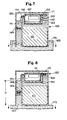
- Figure 1 is a partially torn away perspective view of a passive dosing dispenser which is an embodiment of the present invention;
- Figures 2-12 are reduced scale, simplified sequential sectional views which show a portion of a cycle of the dispenser shown in Figure 1 and which views are taken along section line 2-2 of Figure 1;
- Figure 13 is a fragmentary sectional view of an alternate embodiment of the present invention;
- Figure 14 is a fragmentary sectional view of yet another embodiment of the present invention; and
- Figure 15 is a fragmentary sectional view of still another embodiment of the present invention.
- Referring to the Figures in which identical features are identically designated, Figure 1 shows a self-
priming dispenser 120 embodying the present invention and containing a solid, watersoluble product 121.Dispenser 120 comprises afront wall 122, aback wall 123, twoside walls top wall 128, abottom wall 129,interior partition 134 and abaffle 136. Thebaffle 136 is defined byrigid partitions dispenser 120 are relatively rigid and define a dose-volume measuring cavity 141, aninlet conduit 142, aproduct solution reservoir 143, and adischarge standpipe 144. The outlet port ofdispenser 120 is designated 158. Thedispenser 120 is provided with two rectangular-shaped inlet ports Inlet port 157 is initially made impervious to the passage of liquid therethrough by means of a piece of liquidsoluble tape 192 secured toback wall 123 about the periphery of the port whileinlet port 190 remains pervious to the passage of liquid therethrough at all times. The bottom edge of rectangular-shaped inlet port 157 is designated 151, the bottom edge of rectangular-shaped inlet port 190 is designated 191,partition 131 has its bottom edge designated 152,partition 133 has its top edge designated 153,partition 134 has its top edge designated 154, and the vent passage intermediate thetop wall 128 ofdispenser 120 and theuppermost partition 156 ofbaffle 136 is designated 137. In a preferred embodiment ofdispenser 120,edge 153 is at a greater elevation thanedge 154;edge 154 is at a greater elevation thanedge 151;edge 191 is at a greater elevation thanedge 154; andpartition 181 is at a lower elevation thanedge 154. Together,cavity 141 andconduit 142 form a trap-type inlet. - In Figure 2 is shown a self-
priming dispenser 120 containingsolid product 121 about to be immersed for the first time in a toilet tank (not shown) filled withwater 163 on a bracket or other mounting means (not shown) to a depth such that the FULL level of water in the toilet tank will completely coverinlet port 190. Thedispenser 120 will respond in a manner similar to that shown in Figures 3-5 each time the toilet tank is refilled so long asinlet port 157 remains impervious to the passage of liquid therethrough. - As shown in Figure 3, when the
uncharged dispenser 120 is partially immersed with the liquid soluble, in this case water soluble,tape 192 secured about the periphery ofinlet port 157, water rises within the discharge stand-pipe 144, thereby causing air within the dispenser to vent viapassageway 137 and beneathbaffle 136, throughinlet conduit 142 and dose-volume measuringcavity 141 and ultimately outinlet port 190. Tank water is prevented from entering the dose-volume measuring cavity 141 by means of the watersoluble tape 192 which temporarily renders inletport 157 impervious to the passage of liquid therethrough. Thus,inlet port 190 provides the only air vent so long astape 192 is present. - Because
edge 191 ofinlet port 190 is at a higher elevation thanedge 154 which forms the upper end ofdischarge standpipe 144, toilet tank water eventually overflowsedge 154 and entersproduct solution reservoir 143. This condition is illustrated in Figure 4. When the liquid level insolution reservoir 143 rises abovepartition 181, air contained within the dispenser continues to vent viapassageway 137,inlet conduit 142, measuringcavity 141 and outinlet port 190 until the interior portion of thedispenser 120 located below the uppermost edge ofinlet port 190 is completely flooded by toilet tank water. - If
inlet port 190 is immersed beforesolution reservoir 143 is filled with water, air will continue to vent throughinlet port 190 and will bubble into the tank water, provided the port is properly sized. The latter situation requires only thatinlet port 190 be large enough that the head pressure of the liquid located within the dispenser betweenedge 154 ofpartition 134 andedge 191 ofinlet port 190 be sufficient to overcome the surface tension of the water in the toilet tank acrossinlet port 190. The greater the differential elevation betweenedge 154 andedge 191, thesmaller inlet port 190 may be and still accomplish the desired venting. On the other extreme,inlet port 190 must be sized sufficiently small that air will be allowed to vent as described above, yet toilet tank water will not be permitted to flow back into measuringcavity 141 whilereservoir 143 ofdispenser 120 is filling. Premature flow of toilet tank water throughinlet port 190 whileinlet port 157 remains impervious to the passage of liquid could coveredge 152 ofpartition 131 and preclude complete filling ofsolution reservoir 143. This would of course have an adverse affect upon first flush dispensing ofproduct solution 162. - In yet another embodiment of the present invention,
inlet port 190 could be joined to a snorkel (not shown) projecting abovetop wall 128 ofdispenser 120. Such a snorkel effectively increases the differential elevation betweenedge 154 ofpartition 134 and edge 191 ofinlet port 190. Accordingly, the head pressure of the liquid located between same would likewise be increased. The snorkel could, if desired, be of sufficient height that it remains above the FULL level of the water contained in the toilet tank when the dispenser has been installed therein, thereby providing constant venting of measuringcavity 141 and obviating the need to observe the sizing criteria discussed in the preceding paragraph. - As is shown in Figure 5, when the
dispenser 120 is completely immersed in the toilet tank water, the water in thereservoir 143 in contact with the solid, watersoluble product 121 begins to dissolve the solid product to form aproduct soiution 162. It should be noted, however, that becauseinlet port 157 is impervious to the passage of liquid during the initial immersion of thedispenser 120 into the water, no air-lock isolation is provided between theproduct solution 162 being formed in thereservoir 143 and the toilet tank water in thedischarge standpipe 144 and theinlet conduit 142. Although only a dose-volume of water is vacuum-transferred from the measuringcavity 141 to thesolution reservoir 143 on the first flush cycle, the quantity ofproduct solution 162 issued from the dispenser on the first flush cycle will be greater than that dispensed once the dispenser reaches steady state operation, since thereservoir 143 is flooded to an abnormally high elevation throughdischarge standpipe 144 when the dispenser is initially immersed. - In order to provide first flush dispensing of
product solution 162 from thedispenser 120 it is necessary thatinlet port 157 remain substantially impervious to the passage of liquid therethrough for a period of time sufficient to permit filling of thereservoir 143 with liquid entering through thedischarge standpipe 144. In this regard it should be noted that immersion of thedispenser 120 into the toilet tank water initiates a dissolving action on the watersoluble tape 192blocking inlet port 157. Once theproduct solution reservoir 143 has been filled with liquid,inlet port 190 has served its purpose, and dissolution of the watersoluble tape 192 serves to restore the dispenser to a mode of operation similar to that disclosed in connection with the dispenser embodiments illustrated in Figures 1, 10, 11 and 12 of the aforementioned patent application of Robert S. Dirksing, i.e., a dose-volume ofproduct solution 162 is discharged with each flush cycle of the toilet and thesolid product 121 andproduct solution 162 in thereservoir 143 are isolated from the water in thedischarge standpipe 144 andinlet conduit 142 by means of an air-lock during quiescent periods oncetape 192 has dissolved and the initial flush cycle has been completed. For purposes of clarity this mode is referred to herein as steady state operation. - Figure 6 illustrates the condition prevailing within the
dispenser 120 once theinlet port 157 has become pervious to the passage of liquid therethrough and the toilet has been flushed, causing the water level in the toilet tank to drop. As is clear from Figure 6, the water contained within the dose-volume measuring cavity located aboveedge 151 merely drains back into the toilet tank as the water level falls, leaving the level the water in measuringcavity 141 substantially even withedge 151 ofinlet port 157. Accordingly,inlet port 190 serves no useful function onceinlet port 157 has become pervious to the passage of liquid therethrough. As is also clear from Figure 6, when the level ofwater 163 coincides withedge 151 ofinlet port 157, thetop surface 175 thereof is beneath the level of water disposed in the discharge stand-pipe 144, andproduct solution reservoir 143, causing a partial vacuum to be developed in theheadspace 160. This partial vacuum enables ambient air in the toilet tank to enter throughinlet ports cavity 141 intoinlet conduit 142, Figure 7. This water overflows the top edge 1 53 ofpartition 133 and begins to mix with the portion ofsolution 162 which is disposedadjacent partition 133. The presence ofbaffle 136 causes the incoming water to be directed downwardly and mix substantially withproduct solution 162 in the lower reaches ofsolution reservoir 143.Product solution 162 is displaced fromreservoir 143 and flows intodischarge standpipe 144. - At the time when the level of water in
cavity 141 is about to reach thebottom edge 152 ofpartition 131, Figure 8, a column ofwater 163 andproduct solution 162 is disposed in thedischarge standpipe 144 which column extends upwardly a distance "D" from the elevation of thetop surface 175 of the recedingwater 163. It should be noted that the particular distance "D" will be greater for the first flush cycle than for flush cycles which take place after the dispenser has reached steady state operation. This is due to the initial flooding ofsolution reservoir 143 to an abnormally high elevation. - When, as shown in Figure 9, the level of water in
cavity 141 reachesbottom edge 152 ofpartition 131,passageway 137 is at least partially blocked by liquid attempting to move to the left hand side of the dispenser, andproduct solution 162 is overflowingedge 154. To at least partially blockpassageway 137 it is preferable that a portion of the water from measuringcavity 141 be diverted intochannel 137. This may readily be accomplished by positioningbaffle 136near side wall 125 so that water flow frominlet conduit 142 intoreservoir 143 will back up intopassageway 137. Alternatively, the portion ofpartition 156 extending directly aboveinlet conduit 142 could be eliminated so that water flow throughinlet conduit 142 will be at least partially directed toward the entrace ofpassageway 137. In either case, the cross-section and length ofpassageway 137 are preferably so sized that the passageway presents sufficient resistance to the flow of water as to cause the major portion of the water transferred from measuringcavity 141 to be directed downwardly underbaffle 136. While any number of means well known in the art may be employed to partially blockpassageway 137, it is noteworthy that failure to provide the desired blockage will not cause the dispenser to become inoperative. It is merely less preferred than the described embodiment because it does not maximize the mixing action created by the water and airentering solution reservoir 143. - As the water level in measuring
cavity 141 reachesbottom edge 152 ofpartition 131, air enters thereservoir 143 viainlet ports cavity 141 andinlet conduit 142 and vitiates the vacuum in theheadspace 160. This precipitates collapse of the liquid column of height "D" in the discharge stand-pipe 144, which collapse, in turn, precipitates an inrush of air throughinlet conduit 142 into the portion of theheadspace 160 disposed to the right (as shown in Figure 9) ofbaffle 136. This inrush of air is, in part, diverted downwardly becausebaffle 136 partially obstructs direct flow across the headspace. Furthermore, the small size ofpassageway 137 which is preferably partially blocked by water causes the inrushing air to take the path of least resistance, i.e., downwardly intosolution reservoir 143, thereby virtually blowing a dose-volume ofsolution 162 out of thereservoir 143 as indicated by the arrows in Figure 9. This induces a tempestuous action in thereservoir 143 which results in mixing the water that has just entered the reservoir with the portion ofsolution 162 then remaining in the reservoir, and causes the solution to be sufficiently agitated to induce further dissolution ofsolid product 121. Figure 10 shows thedispenser 120 after the tempestuous action has subsided. - Figure 11 illustrates the condition of the
dispenser 120 as the tank is refilling. Becauseinlet port 157 is at this point pervious to the passage of liquid therethrough, water floods thecavity 141 throughinlet port 157 before the level of water in thestandpipe 144 reachesedge 154. This causes air to be trapped in theheadspace 160 above the reservoir and stand- pipe and provides an air-lock which isolates theproduct 121 and theproduct solution 162 from the water in theinlet conduit 142 and thedischarge standpipe 144. - After reaching steady state operation, i.e.,
inlet port 157 has become pervious to the passage of liquid therethrough, thedispenser 120 will, during quiescent periods while the toilet tank is full ofwater 163, be in the state shown in Figure 12. Thetop surface 171 ofsolution 162 will be slightly belowtop edge 154 ofpartition 134, and have a concave meniscusadjacent edge 154 as shown. Also,toilet tank water 163 will be disposed incavity 141, theinlet conduit 142, and thedischarge standpipe 144. The level of water inconduit 142 will be about the same as instandpipe 144 which level will be below thetop edge 154 ofpartition 134. This is so becauseedge 151 ofentry port 157 is, as stated hereinbefore, at a lower elevation thanedge 154. - The dose-volume of
dispenser 120 which dose-volume is referred to hereinabove is, essentially, the sum of the partial volumes of bothcavity 141 andinlet conduit 142 disposed intermediate the elevation ofedge 151 ofentry port 157 and edge 152 ofpartition 131. Note Figure 11 which shows the dispenser with a dose-volume of water disposed withincavity 141 andconduit 142, and Figure 10 which shows the dispenser after a dose-volume of water has been transferred intoreservoir 143 fromcavity 141 andconduit 142 in the manner described herein. - As has been pointed out earlier herein, were baffle 136 not present in the embodiment illustrated in Figure 1, the dispenser would simply issue a dose-volume of
solution 162 as it is displaced by the incoming dose-volume of makeup water fromcavity 141. While such a dispenser would, upon reaching steady state operation, provide a high degree of product and product solution isolation from the tank water during quiescent periods, it would not provide the same degree of mixing and agitation inreservoir 143 as compared todispenser 120 having abaffle 136 or the equivalent thereof. Thus, thebaffle 136 comprises means for mixing and agitating liquids disposed inreservoir 143 when a rush of air enters theheadspace 160 of the reservor. - The functional design criteria discussed in detail with respect to sizing the various portions of the dispenser relative to one another and which are generally discussed in relation to the embodiment disclosed in Figure 1 of the aforementioned patent application of Robert S. Dirksing likewise have general application to a
dispenser 120 of the type herein illustrated in Figure 1. In particular,dispenser 120 is preferably provided with a quantity of a dry,solid type product 121 disposed in it as shown in Figure 1, and may comprise means (not shown) for being secured in a toilet tank at such an elevation that, when the toilet tank is FULL,cavity 141 will be full of toilet tank water. Furthermore, thedischarge standpipe 144 is sufficiently long and of sufficient volume that lowering the level of water surrounding the dispenser will cause a sufficient degree of vacuum in theheadspace 160 of the dispenser that a predetermined dose-volume of water disposed incavity 141 will be vacuum-transferred into thereservoir 143 viainlet conduit 142 before thedischarge port 158 is uncovered. While a solid mass ofproduct 121 is shown in the figures, it is not intended to thereby limit the present invention. As will be understood from the description contained herein, dispenser embodiments of the present invention may, after reaching steady state operation, also be utilized to dispense a dose-volume of liquid product solution formed, for example, by dissolving a liquid soluble powder contained within the solution reservoir. In such embodiments, the solid, water soluble product cake is eliminated and the product chamber and solution reservoir house a water soluble powder which dissolves to form a liquid product upon immersion of the dispenser in the toilet tank. - An exemplary embodiment of self-priming
dispenser 120 has been fabricated from 1.6 millimeter thick rigid Plexiglas (Registered trademark of Rohm & Haas Company). This exemplary embodiment has a height of about 90 millimeters, a width of about 90 millimeters, and a thickness of about 20 millimeters; its edges 151-154 are spaced from thetop wall 128 about 14 millimeters, 23 millimeters, 7 millimeters and 10 millimeters, respectively; edge 191 ofinlet port 190 is spaced from thetop wall 128 approximately 7 millimeters;partition 181 is spaced approximately 25 millimeters fromtop wall 128;cavity 141 has a dose-volume of about 8 cubic centimeters;inlet conduit 142 has a cross-section of about 2 millimeters by about 20 millimeters;inlet port 190 has a width of approximately 5 millimeters and a height of approximately 4 millimeters;inlet port 157 has a width of approximately 24 millimeters and a height of approximately 6 millimeters; anddischarge standpipe 144 has a cross-section of about 16 millimeters by about 20 millimeters. Also, baffle 136 of the exemplary embodiment illustrated in Figure 12 is disposed about 3 millimeters fromdispenser side wall 125 and measures approximately 52 millimeters in width by 25 millimeters in height.Passageway 137 has a cross-section of about 1 millimeter by about 20 millimeters. As is shown in Figures 1-11, the top end of inlet conduit 142 (which top end is defined as edge 1 53 of partition 133) extends to a greater height in the upper reaches ofreservoir 143 than the top end of the discharge standpipe 144 (which top end is defined asedge 154 of partition 134). The strip of watersoluble tape 192, secured to backwall 123 about the periphery ofinlet port 157, consisted of dissolving paper as available from Gilbreth International Corporation of Cornwells Heights, Pennsylvania coated on the surface contacting backwall 123 with Prim's gift wrapping adhesive as available from Hyco Products of Cincinnati, Ohio. When immersed, the paper dissolves, thereby renderinginlet port 157 pervious to the passage of liquid. - While the exemplary embodiment of the
dispenser 120 was constructed by adhesively securing sections of Plexiglas to one another, other relatively rigid materials which are substantially inert with respect to the intended product and aqueous solutions thereof can be used to constructdispenser 120. For example, a dispenser having the desired passageways could be vacuum thermoformed in two sections of a material such as polyvinyl chloride having an initial thickness of about 0.5 millimeter, thesolid product 121 inserted therebetween and the two sections thereafter secured to one another as by heat sealing, adhesives, etc, along a line of contact substantially coinciding with section line 2-2 of Figure 1. - Furthermore, suitable means other than liquid soluble, i.e., water soluble,
tape 192 may be employed to renderinlet port 157 temporarily impervious to the passage of liquid therethrough. For example, a strip of any type of non-water soluble, liquid impervious material may be secured in place by means of any suitable liquid soluble, i.e, water soluble, adhesive such as a dextrin adhesive, as available from H. B. Fuller Company of St. Paul, Minnesota. Upon immersion in water, the adhesive dissolves, allowing the liquid impervious strip to fall away and renderinlet port 157 pervious to the passage of liquid. Alternatively, a continuous coating comprised of a water soluble film forming agent such as polyvinyl alcohol, as available in 2 mil thick sheets, 88 percent hydrolyzed, from Monosol Division of Chris Craft, Gary, Indiana, may be secured across the surface ofinlet port 157 to render it temporarily impervious to the passage of liquid therethrough. In a preferred embodiment, the continuous coating of water soluble film forming agent is procured in sheet form and secured in place by moistening the periphery ofinlet port 157 prior to placing the sheet in contact withback wall 123. The moisture causes the sheet to become tacky and adhere to theback wall 123 of the dispenser. Upon sustained immersion in water, the continuous film dissolves,rendering inlet port 157 pervious to the passage of liquid. As will be appreciated by those skilled in the art, the particular material selected to renderinlet port 157 temporarily impervious to the passage of liquid may be applied to the interior or the exterior surface ofback wall 123, or merely bridged across the opening comprisinginlet port 157. Furthermore, strips of water soluble material may be used in combination with water soluble adhesives or water soluble films to accomplish the desired objective. It is only necessary that the particular water soluble material or materials selected to temporarily render theinlet port 157 impervious to the passage of liquid not be adversely affected by either the solid product contained within the dispenser prior to use or by storage conditions likely to be encountered prior to the dispenser's being placed into service, i.e., temperature, humidity, etc. - A
dispenser 120 of the type generally illustrated in Figure 1 permits the use of a symmetrically shaped, solid, watersoluble product 121, provides a high degree of surface exposure of the solid product to theproduct solution 162, and a highly satisfactory flow of incomingtoilet tank water 163 across the solid product. However, embodiments of the present invention may with equal facility be incorporated in either single compartment or multiple compartment dispensers of the type generally illustrated in Figures 1, 10 and 11 of the aforementioned patent application of Robert S. Dirksing. In such embodiments, theinlet ports 57 and 257, illustrated in Figures 1, 10 and 11 respectively of said application, could be covered with water soluble tape, and an additional inlet port provided at an elevation greater than that corresponding to edge 51, i.e., as in the top wall, front wall or back wall portion of the dispenser. - In Figure 13 is shown yet another embodiment of the present invention wherein a self-priming
dispenser 220 generally similar to that described in connection with Figure 1 incorporates asecond inlet port 257 having a piece of watersoluble tape 292 secured entirely about its periphery. Said water soluble tape has afirst inlet port 290 pervious to the passage of liquid therethrough, said first inlet port having itslowermost edge 291 at an elevation greater than that of thelowermost edge 251 of said second inlet port and that ofedge 254 ofpartition 234. Thedispenser 220 functions in a manner substantially as described in connection with the embodiment of Figure 1, i.e., product and product solution isolation are not achieved untiltape 292 has dissolved and the first flush cycle has been completed. - In Figure 14 is illustrated another self-priming
dispenser 320 of the present invention having asecond inlet port 357, said second inlet port being made temporarily impervious to the passage of liquid therethrough by means of a piece of watersoluble tape 392 secured about the bottom and sides of said second inlet port. Afirst inlet port 390 is provided within the measuring cavity in the area above theuppermost edge 391 of the watersoluble tape 392.Edge 391 which also comprises the lowermost edge ofinlet port 390 is at an elevation greater than that of thelowermost edge 351 ofinlet port 357 and that ofedge 354 ofpartition 334. Functioning of thedispenser 320 is generally similar to that of the dispensers illustrated in Figures 1 and 13. - In Figure 15 is shown yet another embodiment of the present invention wherein a self-priming
dispenser 420 generally similar to that described in connection with Figure 1 incorporates asecond inlet port 457 having a continuous coating comprised of a film forming agent such as liquidsoluble gelatin 492 or the like secured entirely about its periphery, said continuous coating of liquid soluble gelatin having afirst inlet port 490 pervious to the passage of liquid therethrough, said first inlet port having itslowermost edge 491 disposed at an elevation greater than that of thelowermost edge 451 of saidsecond inlet port 457 and that ofedge 454 ofpartition 434. Thedispenser 420 functions in a manner substantially as described in connection with the embodiments of Figures 1, 13 and 14. - As will be apparent to those skilled in the art, self-priming dispenser embodiments of the present invention may be employed in plural sections to co-dispense plural component products which need to be isolated not only from the toilet tank water during quiescent periods intermediate flush cycles, but also from each other prior to use.
- While particular embodiments of the present invention have been illustrated and described, it will be obvious to those skilled in the art that various changes and modifications can be made without departing from the spirit and scope of the invention and it is intended to cover, in the appended claims, all such modifications that are within the scope of this invention. Moreover, while the present invention has been described in the context of dispensing a toilet tank additive, it is not intended to thereby limit the present invention.
Claims (11)
Priority Applications (1)
| Application Number | Priority Date | Filing Date | Title |
|---|---|---|---|
| AT79200430T ATE1357T1 (en) | 1978-08-14 | 1979-08-02 | AUTOMATICALLY STARTING TANK WITH NO MOVING PARTS. |
Applications Claiming Priority (2)
| Application Number | Priority Date | Filing Date | Title |
|---|---|---|---|
| US05/933,400 US4186856A (en) | 1978-08-14 | 1978-08-14 | Self-priming passive dosing dispenser |
| US933400 | 1978-08-14 |
Publications (2)
| Publication Number | Publication Date |
|---|---|
| EP0008148A1 EP0008148A1 (en) | 1980-02-20 |
| EP0008148B1 true EP0008148B1 (en) | 1982-07-21 |
Family
ID=25463878
Family Applications (1)
| Application Number | Title | Priority Date | Filing Date |
|---|---|---|---|
| EP79200430A Expired EP0008148B1 (en) | 1978-08-14 | 1979-08-02 | Self priming passive dosing dispenser |
Country Status (10)
| Country | Link |
|---|---|
| US (1) | US4186856A (en) |
| EP (1) | EP0008148B1 (en) |
| JP (1) | JPS5561628A (en) |
| AT (1) | ATE1357T1 (en) |
| AU (1) | AU522445B2 (en) |
| CA (1) | CA1100708A (en) |
| DE (1) | DE2963368D1 (en) |
| ES (1) | ES483351A1 (en) |
| GR (1) | GR65652B (en) |
| MX (1) | MX150901A (en) |
Families Citing this family (20)
| Publication number | Priority date | Publication date | Assignee | Title |
|---|---|---|---|---|
| US4251012A (en) * | 1979-07-20 | 1981-02-17 | The Procter & Gamble Company | Passive liquid dosing dispenser |
| US4307474A (en) * | 1980-05-28 | 1981-12-29 | The Procter & Gamble Company | Passive dosing dispenser exhibiting improved resistance to clogging |
| US4305162A (en) * | 1980-11-10 | 1981-12-15 | The Procter & Gamble Company | Passive dosing dispenser employing captive air bubble to provide product isolation |
| US4432102A (en) * | 1981-10-21 | 1984-02-21 | American Cyanamid Co. | Dispensing package for automatically releasing a controlled amount of an additive solution into a water tank and bowl |
| US4507811A (en) * | 1981-07-07 | 1985-04-02 | The Clorox Company | Toilet bowl dispenser |
| US4419771A (en) * | 1982-02-08 | 1983-12-13 | The Drackett Company | Passive dispenser |
| US4375109A (en) * | 1982-02-22 | 1983-03-01 | The Drackett Company | Passive dispenser having a double air vent system |
| US4438534A (en) * | 1982-03-03 | 1984-03-27 | The Drackett Company | Passive dispenser |
| US4434136A (en) | 1982-03-08 | 1984-02-28 | The Proctor & Gamble Company | Tapered-bottom bleach cake for sanitation dosing dispenser |
| US4459710A (en) * | 1982-10-18 | 1984-07-17 | The Drackett Company | Passive dispenser |
| US4491988A (en) * | 1983-01-28 | 1985-01-08 | Economics Laboratory, Inc. | In-tank toilet bowl cleaner dispenser |
| US4451941A (en) * | 1983-04-18 | 1984-06-05 | Sterling Drug, Inc. | Toilet bowl sanitizer dispenser |
| US4539717A (en) * | 1983-11-04 | 1985-09-10 | Waldwick Plastics Corporation | Submergible self-priming dispenser |
| US4558471A (en) * | 1984-07-20 | 1985-12-17 | The Procter & Gamble Company | Passive dosing dispenser featuring high strength initial cleaning action |
| US4745638A (en) * | 1985-07-30 | 1988-05-24 | The Drackett Company | Passive dispenser having delayed discharge |
| US5038416A (en) * | 1989-08-17 | 1991-08-13 | Horne Peggy L | Water closet water saving device and dispenser |
| US6055679A (en) * | 1995-03-03 | 2000-05-02 | S. C. Johnson & Son, Inc. | Passive lavatory cleanser dispensing system |
| FR2746915A1 (en) * | 1996-03-27 | 1997-10-03 | Tournassat Claude | DEVICES FOR DOSING FLUIDS UNDER EFFECT OF LEVEL CHANGES |
| WO2001096676A1 (en) * | 2000-06-08 | 2001-12-20 | Unilever Plc | Dosing device for toilets |
| US11224284B2 (en) | 2020-02-18 | 2022-01-18 | Colgate-Palmolive Company | Personal care system and fluid supply system thereof |
Family Cites Families (14)
| Publication number | Priority date | Publication date | Assignee | Title |
|---|---|---|---|---|
| US650161A (en) * | 1899-09-02 | 1900-05-22 | Joseph Williams | Deodorizer. |
| US1175032A (en) * | 1914-04-01 | 1916-03-14 | Edward R Williams | Method of disinfecting or deodorizing flushing-tanks. |
| US3061842A (en) * | 1960-08-09 | 1962-11-06 | Roy P Woodruff | Deodorant dispenser |
| US3407412A (en) * | 1966-06-09 | 1968-10-29 | Diamond Spear Co | Device for supplying chemical disinfectant and the like to the trap of a toilet bowl |
| US3444566A (en) * | 1967-06-08 | 1969-05-20 | Clifton T Spear | Device for introducing substances into a toilet bowl trap |
| GB1219200A (en) * | 1968-05-29 | 1971-01-13 | Reckitt & Colmann Prod Ltd | Improvements in or relating to dispensing containers for use in flushing cisterns |
| US3869069A (en) * | 1970-06-15 | 1975-03-04 | Days Ease Home Prod Corp | Suspended dissoluble disinfectant container |
| US3769640A (en) * | 1971-03-18 | 1973-11-06 | Castronovo & Edwards Glo Bowl | Dispenser |
| US3772715A (en) * | 1971-08-19 | 1973-11-20 | Gillette Co | Container-dispenser package for plurality of products |
| US3781926A (en) * | 1972-03-27 | 1974-01-01 | Levey R | Adjustable sanitizer dispenser for toilet tank |
| FR2244880B1 (en) * | 1973-09-21 | 1982-11-05 | Oreal | |
| DE2349067A1 (en) * | 1973-09-29 | 1975-04-10 | Henkel & Cie Gmbh | AUTOMATIC TOILET CLEANER |
| US4064572A (en) * | 1976-05-19 | 1977-12-27 | Shell Oil Company | Level actuated apparatus for delivering chemicals |
| US4171546A (en) * | 1977-10-21 | 1979-10-23 | The Procter & Gamble Company | Passive dosing dispenser |
-
1978
- 1978-08-14 US US05/933,400 patent/US4186856A/en not_active Expired - Lifetime
-
1979
- 1979-08-02 AT AT79200430T patent/ATE1357T1/en not_active IP Right Cessation
- 1979-08-02 DE DE7979200430T patent/DE2963368D1/en not_active Expired
- 1979-08-02 EP EP79200430A patent/EP0008148B1/en not_active Expired
- 1979-08-13 GR GR59830A patent/GR65652B/en unknown
- 1979-08-13 AU AU49856/79A patent/AU522445B2/en not_active Ceased
- 1979-08-13 ES ES483351A patent/ES483351A1/en not_active Expired
- 1979-08-13 MX MX178896A patent/MX150901A/en unknown
- 1979-08-14 CA CA333,705A patent/CA1100708A/en not_active Expired
- 1979-08-14 JP JP10350279A patent/JPS5561628A/en active Pending
Also Published As
| Publication number | Publication date |
|---|---|
| ATE1357T1 (en) | 1982-08-15 |
| EP0008148A1 (en) | 1980-02-20 |
| ES483351A1 (en) | 1980-08-16 |
| CA1100708A (en) | 1981-05-12 |
| AU4985679A (en) | 1980-02-21 |
| DE2963368D1 (en) | 1982-09-09 |
| MX150901A (en) | 1984-08-13 |
| GR65652B (en) | 1980-10-16 |
| JPS5561628A (en) | 1980-05-09 |
| US4186856A (en) | 1980-02-05 |
| AU522445B2 (en) | 1982-06-03 |
Similar Documents
| Publication | Publication Date | Title |
|---|---|---|
| US4186856A (en) | Self-priming passive dosing dispenser | |
| EP0004990B1 (en) | Passive dosing dispenser employing trapped air bubble to provide air-lock | |
| EP0001671B1 (en) | Passive dosing dispenser for a toilet tank additive | |
| CA1130507A (en) | Passive liquid dosing dispenser | |
| US4307474A (en) | Passive dosing dispenser exhibiting improved resistance to clogging | |
| NZ203237A (en) | Passive dispenser with dual sections:siphonic section and gravitational section | |
| US4480341A (en) | Passive dispenser | |
| US3358299A (en) | Maintenance of urinals, water closet basins and the like | |
| CA1155604A (en) | Passive dosing dispenser employing captive air bubble to provide product isolation | |
| NZ203234A (en) | Toilet cistern dispenser:multiple chambers emptied by siphonage during flushing | |
| US4321714A (en) | Apparatus for defecating a urinal by means of foam | |
| US4491988A (en) | In-tank toilet bowl cleaner dispenser | |
| US4370763A (en) | Automatic dosing dispenser | |
| US4451941A (en) | Toilet bowl sanitizer dispenser | |
| US4745638A (en) | Passive dispenser having delayed discharge | |
| GB2115850A (en) | Passive dispenser having a double air vent system | |
| US4738833A (en) | Self-regulating dosing dispenser | |
| US4635302A (en) | Toilet bowl cleaner dispenser | |
| PT1287211E (en) | Liquid dispenser for cleaning toilet bowls | |
| US5839128A (en) | Antiseptic solution dispenser | |
| EP0140692B1 (en) | Lavatory cistern dispenser | |
| EP1386040A1 (en) | Down-stroke dispenser | |
| WO2004016869A1 (en) | Apparatus for the dispensing of a liquid, adapted to be placed in a volume of liquid with fluctuating liquid level, particularly adapted for metered disposal of chemicals to a cistern | |
| US4821346A (en) | Toilet bowl cleaning composition dispenser | |
| JPS62117925A (en) | Dispenser |
Legal Events
| Date | Code | Title | Description |
|---|---|---|---|
| PUAI | Public reference made under article 153(3) epc to a published international application that has entered the european phase |
Free format text: ORIGINAL CODE: 0009012 |
|
| AK | Designated contracting states |
Designated state(s): AT BE CH DE FR GB IT NL SE |
|
| 17P | Request for examination filed | ||
| ITF | It: translation for a ep patent filed | ||
| GRAA | (expected) grant |
Free format text: ORIGINAL CODE: 0009210 |
|
| AK | Designated contracting states |
Designated state(s): AT BE CH DE FR GB IT NL SE |
|
| REF | Corresponds to: |
Ref document number: 1357 Country of ref document: AT Date of ref document: 19820815 Kind code of ref document: T |
|
| REF | Corresponds to: |
Ref document number: 2963368 Country of ref document: DE Date of ref document: 19820909 |
|
| ITTA | It: last paid annual fee | ||
| PGFP | Annual fee paid to national office [announced via postgrant information from national office to epo] |
Ref country code: GB Payment date: 19940725 Year of fee payment: 16 |
|
| PGFP | Annual fee paid to national office [announced via postgrant information from national office to epo] |
Ref country code: FR Payment date: 19940809 Year of fee payment: 16 |
|
| PGFP | Annual fee paid to national office [announced via postgrant information from national office to epo] |
Ref country code: AT Payment date: 19940812 Year of fee payment: 16 |
|
| PGFP | Annual fee paid to national office [announced via postgrant information from national office to epo] |
Ref country code: CH Payment date: 19940815 Year of fee payment: 16 |
|
| PGFP | Annual fee paid to national office [announced via postgrant information from national office to epo] |
Ref country code: DE Payment date: 19940816 Year of fee payment: 16 |
|
| PGFP | Annual fee paid to national office [announced via postgrant information from national office to epo] |
Ref country code: SE Payment date: 19940817 Year of fee payment: 16 |
|
| PGFP | Annual fee paid to national office [announced via postgrant information from national office to epo] |
Ref country code: NL Payment date: 19940831 Year of fee payment: 16 |
|
| PGFP | Annual fee paid to national office [announced via postgrant information from national office to epo] |
Ref country code: BE Payment date: 19941012 Year of fee payment: 16 |
|
| EAL | Se: european patent in force in sweden |
Ref document number: 79200430.1 |
|
| PG25 | Lapsed in a contracting state [announced via postgrant information from national office to epo] |
Ref country code: GB Effective date: 19950802 Ref country code: AT Effective date: 19950802 |
|
| PG25 | Lapsed in a contracting state [announced via postgrant information from national office to epo] |
Ref country code: SE Effective date: 19950803 |
|
| PG25 | Lapsed in a contracting state [announced via postgrant information from national office to epo] |
Ref country code: CH Effective date: 19950831 Ref country code: BE Effective date: 19950831 |
|
| BERE | Be: lapsed |
Owner name: THE PROCTER & GAMBLE CY Effective date: 19950831 |
|
| PG25 | Lapsed in a contracting state [announced via postgrant information from national office to epo] |
Ref country code: NL Effective date: 19960301 |
|
| GBPC | Gb: european patent ceased through non-payment of renewal fee |
Effective date: 19950802 |
|
| REG | Reference to a national code |
Ref country code: CH Ref legal event code: PL |
|
| PG25 | Lapsed in a contracting state [announced via postgrant information from national office to epo] |
Ref country code: FR Effective date: 19960430 |
|
| NLV4 | Nl: lapsed or anulled due to non-payment of the annual fee |
Effective date: 19960301 |
|
| PG25 | Lapsed in a contracting state [announced via postgrant information from national office to epo] |
Ref country code: DE Effective date: 19960501 |
|
| EUG | Se: european patent has lapsed |
Ref document number: 79200430.1 |
|
| REG | Reference to a national code |
Ref country code: FR Ref legal event code: ST |
|
| PLBE | No opposition filed within time limit |
Free format text: ORIGINAL CODE: 0009261 |
|
| STAA | Information on the status of an ep patent application or granted ep patent |
Free format text: STATUS: NO OPPOSITION FILED WITHIN TIME LIMIT |