EP0007368B1 - Expandable vehicle - Google Patents
Expandable vehicle Download PDFInfo
- Publication number
- EP0007368B1 EP0007368B1 EP78900181A EP78900181A EP0007368B1 EP 0007368 B1 EP0007368 B1 EP 0007368B1 EP 78900181 A EP78900181 A EP 78900181A EP 78900181 A EP78900181 A EP 78900181A EP 0007368 B1 EP0007368 B1 EP 0007368B1
- Authority
- EP
- European Patent Office
- Prior art keywords
- vehicle
- hood
- body panel
- expandable
- accordance
- Prior art date
- Legal status (The legal status is an assumption and is not a legal conclusion. Google has not performed a legal analysis and makes no representation as to the accuracy of the status listed.)
- Expired
Links
- 238000003860 storage Methods 0.000 claims description 28
- 239000006096 absorbing agent Substances 0.000 claims description 7
- 230000035939 shock Effects 0.000 claims description 7
- 238000005304 joining Methods 0.000 claims description 5
- 230000007246 mechanism Effects 0.000 description 10
- 241000283973 Oryctolagus cuniculus Species 0.000 description 6
- 230000004048 modification Effects 0.000 description 6
- 238000012986 modification Methods 0.000 description 6
- 239000004744 fabric Substances 0.000 description 5
- 238000000034 method Methods 0.000 description 5
- 229910001220 stainless steel Inorganic materials 0.000 description 5
- 239000010935 stainless steel Substances 0.000 description 5
- 238000007789 sealing Methods 0.000 description 3
- 230000008901 benefit Effects 0.000 description 2
- 238000010276 construction Methods 0.000 description 2
- 229920001971 elastomer Polymers 0.000 description 2
- 239000011152 fibreglass Substances 0.000 description 2
- 239000011521 glass Substances 0.000 description 2
- 238000000465 moulding Methods 0.000 description 2
- 239000004033 plastic Substances 0.000 description 2
- 238000000926 separation method Methods 0.000 description 2
- 239000004677 Nylon Substances 0.000 description 1
- 230000000712 assembly Effects 0.000 description 1
- 238000000429 assembly Methods 0.000 description 1
- 230000006835 compression Effects 0.000 description 1
- 238000007906 compression Methods 0.000 description 1
- 239000005357 flat glass Substances 0.000 description 1
- 239000006260 foam Substances 0.000 description 1
- 238000013023 gasketing Methods 0.000 description 1
- 230000005484 gravity Effects 0.000 description 1
- 229920002681 hypalon Polymers 0.000 description 1
- 238000009434 installation Methods 0.000 description 1
- 238000004519 manufacturing process Methods 0.000 description 1
- 239000000463 material Substances 0.000 description 1
- 230000013011 mating Effects 0.000 description 1
- 239000012528 membrane Substances 0.000 description 1
- 239000002184 metal Substances 0.000 description 1
- 239000002991 molded plastic Substances 0.000 description 1
- 229920001778 nylon Polymers 0.000 description 1
- 230000009467 reduction Effects 0.000 description 1
- XLYOFNOQVPJJNP-UHFFFAOYSA-N water Substances O XLYOFNOQVPJJNP-UHFFFAOYSA-N 0.000 description 1
Images


Classifications
-
- B—PERFORMING OPERATIONS; TRANSPORTING
- B60—VEHICLES IN GENERAL
- B60P—VEHICLES ADAPTED FOR LOAD TRANSPORTATION OR TO TRANSPORT, TO CARRY, OR TO COMPRISE SPECIAL LOADS OR OBJECTS
- B60P3/00—Vehicles adapted to transport, to carry or to comprise special loads or objects
- B60P3/32—Vehicles adapted to transport, to carry or to comprise special loads or objects comprising living accommodation for people, e.g. caravans, camping, or like vehicles
- B60P3/34—Vehicles adapted to transport, to carry or to comprise special loads or objects comprising living accommodation for people, e.g. caravans, camping, or like vehicles the living accommodation being expansible, collapsible or capable of rearrangement
- B60P3/341—Vehicles adapted to transport, to carry or to comprise special loads or objects comprising living accommodation for people, e.g. caravans, camping, or like vehicles the living accommodation being expansible, collapsible or capable of rearrangement comprising flexible elements
Definitions
- the invention relates to an expandable vehicle of the type comprising a vehicle body defining an outer configuration for the vehicle and comprising a movable panel member and a stationary body frame as well as means for joining said movable panel member to the stationary body frame, said means comprising pivotable links and a collapsible hood, the movable panel member being pivotable about a pivot axis through an angle of substantially 90° from a closed position, into which confrontable edges of said panel member and said body frame confront each other, into an open position in which the hood is expanded to provide an enclosed enlarged usable volume.
- An expandable vehicle of the above type is known from GB-A-1 196 077.
- This prior art expandable vehicle shows drawbacks in so far as there is no increased headroom established when the movable body panel member is in its open position. This is disadvantageous in so far that even in the extended condition one is unable to stand or stoop comfortably within the expanded volume.
- the highest point of the expandable vehicle according to GB-A-1 196 077 in the open condition of the hood is not higher than the highest point of the originally enclosed volume as defined by the vehicle roof.
- the invention as claimed is intended to provide a remedy. It solves the problem of how to design an expandable vehicle, in particular an automotive vehicle, where the expanded volume has an increased headroom whilst providing a total enclosed expanded volume in said open position, greater than twice that of the original enclosed usable volume in said closed position.
- the advantages offered by the invention are mainly that an increased headroom is provided which makes the inventive vehicle suitable for usage in the fields of education, recreation, medical assistance and creative arts, as well as for military use.
- FIGS. 1 A, 1B and 1 C the basic underlying geometric principals upon which the present invention is based are illustrated.
- the basic underlying concept of the present invention may be understood by representations of a cubic or rectangular volume which is intersected by an imaginary plane diagonally from corner to corner so that the volume is bisected.
- Figures 1 A-1 C refer to various stages of the same embodiment as it moves from a closed position ( Figure 1A) to an open position ( Figure 1C).
- Figure 1A illustrates a rectangular compartment 10 such as would be enclosed by an automobile type vehicle, such as a car or van, the compartment 10 being bisected by an imaginary diagonal plane 11 which includes edges 14, 16 of opposed pairs of compartment walls. It can be seen that the plane 11 defines two compartment portions 12a, 12b within the compartment 10 which compartment 10 is shown in the closed position in Figure 1 A.
- compartment portions 12a, 12b are hinged to one another for pivotal movement about the edge 14, and are otherwise separated from one another along a line of separation defined by the intersection of the plane 11 with the compartment 10 to provide a pair of half volumes, it is possible to provide an expanded enclosed volume by way of an according folding hood covering 18 by rotation of one of the half volumes 12a approximately 90° about one of the two edges common to both half volumes.
- the hood 18 is joined at opposite ends thereof to confronting edges 20a, 20b of compartment portions 12a, 12b, respectively.
- the top of the hood 18 defines or circumscribes a circular arc terminating along the furthest separated edges of compartment portions 12a, 12b. It can be shown that if the original volume is a cube, the ratio of volumes enclosed by compartment 10 when in its expanded or open configuration (Figure 1 C) as compared to its closed configuration ( Figure 1A) is 2.54 to 1 or an increase in volume of 154%. In addition, the arch described by the top of hood 18 creates an increased headroom for the enclosed expanded volume as shown in Figure 1 C by the dotted line 9 which represents the original headroom.
- Figures 1 D-1 F illustrate a compartment 20 which, instead of being separable into two compartments defined by a diagonal plane such as 22, has one portion 24a which in profile has a "dog leg” bend. Portion 24a is joined for relative pivotable movement to the remaining portion 24b along edge 26.
- An accordion folding hood 28 is joined at opposite ends thereof to confronting edges 30a, 30b on the separable compartment portions 24a, 24b, respectively, the accordion hood 28 being arranged to fold over at the "dog leg” bend 27 when compartment portion 24a is swung into closed confronting relationship with portion 24b as in Figure 1D
- Figures 1 D-1 F has the advantage of providing a maximum vertical height H within the expanded compartment 20 (Figure 1 E) which is greater than the length of diagonal line 29 defined by imaginary plane 22 ( Figure 1 D), whereas the expanded compartment 10 of Figures 1A-1C has a maximum vertical height which is determined by the length of diagonal 31.
- the expanded compartment 20 thereby has an even greater percentage volume increase over its unexpanded volume than the increase obtained by expanding the compartment 10 of Figures 1 A-1 C.
- compartment portion 24a, 24b does not coincide with the diagonal line 29
- a passageway including a door leading into and out of compartment 20 may be easily located on the end wall of compartment portion 24b without interference from diagonally disposed hood support members as would be encountered in connection with the folding hood 18 as it is embodied within compartment 10 of Figures 1A-1C.
- FIG. 1G-11 Another expandable compartment 30 is shown in Figure 1G-11.
- the volume enclosed by the expanded compartment 30 as in Figure 11 is also substantially greater than the volume within closed compartment portions 32a, 32b .
- Compartment portions 32a, 32b are joined to each other for relative pivotal movement about an axis 34 which is in the vicinity of and substantially parallel to the outside lower right edge of compartment 30.
- a passageway may also be provided on the endwalls of the compartment portion 32b without interference from any supporting structures for the folding hood 36.
- a vehicle 40 such as the standard 1977 Volkswagen Rabbit appears in Figure 2 in an unexpanded, normal running configuration, and in Figures 18-20 as modified according to the present invention.
- the preferred expansion technique applied to the vehicle 40 most closely resembles that shown and described above in connection with Figures 1 D-1 F.
- a generally "dog leg" shaped body portion 42a is joined for relative pivotal movement to the remaining vehicle body 42b by a hinge assembly 44 having an axis substantially parallel to and in the vicinity of the lower rear edge of the vehicle 40.
- the unexpanded vehicle 40 of Figure 2 is preferably nearly identical in profile to the conventional vehicle as it appears before modification according to the invention, except for a relatively slight bulge extending from the mid-roof line down across the back of the vehicle 40, owing to the generally "dog leg" shape of the separable movable body portion 42a.
- the expandable vehicle 40 shown in Figures 2 and 3 will preferably undergo only minor variation regarding the usable interior space occupied within the vehicle before it is modified in accordance with the present invention, i.e. the standard production automobile.
- Such minor variations preferably include, by way of example;
- vehicle 40 can be expanded to provide an enclosed, hooded sleeping surface which is, by way of example, six feet (182.9 cm) in length and three feet, four inches (101.6 cm) wide at the narrowest point between wheel wells 84 as shown in Figure 4.
- the maximum height of the expanded accordion hood 46 as shown in Figure 3 is four feet, six inches (137.2 cm) above the sleeping surface.
- the rear body panel and a portion of the rear side panel of the standard vehicle are preferably modified to accommodate the required storage compartment for the accordion hood 46, with the details of the storage compartment being set out below in connection with Figures 5 and 12.
- movable body portion 42a which can be constructed of fiberglass, for example, and would be only slightly larger in height and width than the combined original equipment panels.
- confronting edges 48a of panels 42a should preferably accommodate weather proofing seals which may be conventional and are therefore not shown in the drawing, the seals being arranged to compress against corresponding confronting edges 48b of vehicle body or stationary body frame 42b to form a weather tight seal when body portion 42a is securely closed against vehicle body 42b as shown in Figure 2.
- Figure 3 illustrates some of the basic structure associated with the expansion of vehicle 40 from the normal running configuration shown in Figure 2.
- accordion folding hood 46 is joined at opposite ends thereof in the vicinity of confronting edge 48a, 48b, to the movable body portion 42a, and the vehicle body 42b, respectively.
- the accordion folding hood 46 preferably has pleated folding sections 50 arranged between associated- hood support members 52, the support members 52 being shown and described in further detail in connection with Figures 4, 5 and 8-11.
- the sleeping pad support panel 54 being preferably hinged at 56 for relative pivotal movement of its rearward portion 58 with respect to its forward portion 60.
- the forward portion 60 of panel 54 preferably rests horizontally across shifted rear seat 62 and folded rear seat back 64, and extends back through the rear luggage/storage compartment of vehicle 40.
- Rear bumper 66 on vehicle 40 is mounted for pivotal movement with respect to the vehicle 40 about an axis which substantially coincides with the axis of hinge assembly 44, the bumper 66 being arranged to move in unison with the movable body portion 42a, as detailed later in connection with Figures 6 and 7.
- a pivoted locking and support brace 68 which is preferably provided and joined at its ends to the body portion 42a and the vehicle body 42b, respectively, as shown.
- rear window glass 70 may be hinged as at 72 to allow the glass 70 to swing out and away from the rear end of the sleeping pad support panel 54, should an occupant desire to open the glass 70 when using the expanded vehicle 40 in its expanded configuration.
- FIG 4 An interior view of the vehicle 40 as expanded in Figure 3 is given in Figure 4.
- the accordion folding hood 46 and other portions of the vehicle 40 are omitted for purposes of clarity.
- hood support members 52 are shown in their expanded configuration, pivotally separated from one another about an axis which substantially coincides with the axis of hinge assembly 44.
- each of the members 52 preferably has a hinged joint 80, described and shown in further detail in Figures 10 and 11.
- the joints 80 allow the upper portions of each of the hood support members 52 to preferably fold sideways in unison with the folding hood (unshown) and into a hood storage compartment which is shown and will be described in greater detail in connection with Figures 5 and 12.
- a sleeping pad 82 is shown in Figure 4 as preferably placed over support panel 54, the rear portion 58 of the panel 54 preferably being swung out to occupy the rear of the expanded compartment in vehicle 40.
- the narrowest portion of the sleeping pad 82 (and support panel 54) is defined by the distance between wheel wells 84, this distance being approximately three feet, four inches (101.6 cm) wide for the 1977 "Volkswagen Rabbit".
- FIG 5 a preferred arrangement is shown in which folding hood 46 is collapsed into the hood storage compartment 86 preferably defined in part by a "U"-shaped channel. Compartment 86 is preferably contiguously joined to and extends from confronting edge 48b of the vehicle body 42b within the interior of the vehicle 40. Body portion 42a is illustratively shown in Figure 5 as being rearwardly exploded away from the vehicle body:42b for purposes of clarity.
- hood storage compartment 86 preferably has a generally flattened "U"-shaped cross section of sufficient width to accommodate hood 46 when folded in unison with its associated support members 52, the members 52 preferably collapsing adjacent one another to define an essentially flat row of collapsed support members 52 within the compartment 86 as shown in Figure 5.
- the "U"-shaped compartment is contiguously joined to and follows the "dog leg” contour of the confronting edge of vehicle body 42b.
- the compartment 86 therefore extends inwardly and across the top of the rear luggage/storage compartment of the vehicle 40.
- the lower ends of the channel 86 are joined to the lower interior body portion of the vehicle body 42b as shown in Figure 5.
- a hood compartment cover 88 which is shaped to accommodate portions of the folding hood 46, hood support members 52 and support member hinge joints 80 which may extend up above the compartment 86 after the hood 46 is collapsed and stored therein upon movement of the body portion 42a to its closed configuration.
- hinge assembly 44 in addition to its normal function of joining the body portion 42a to the vehicle body 42b for relative pivotal movement, acts to pivot each of the hood support members 52, the ends of each of the support members 52 being connected for said pivotal movement about the axis of hinge assembly 44 in the vicinity of each end of the hinge assembly 44 as shown in Figure 5.
- the movable body portion 42a is shown in Figure 5 as exploded away from the vehicle body 42b merely for purposes of clarity, with the lower end of body portion 42a in actuality being joined to the vehicle body 42b for relative pivotal movement preferably by joining the lower edge of the body portion 42a for pivotal movement about the axis of hinge assembly 44, this construction is shown in detail and discussed later in regard to Figures 6-9.
- Two openings 90 are preferably provided through the body portion 42a in the vicinity of the lower left and right sides thereof, respectively, and are preferably dimensioned to allow conventional type bumper shock absorbers 92 to pass therethrough. These shock absorbers 92 are shown in Figures 6 and 7 and will be described in greater detail in connection therewith.
- Figures 6 and 7 illustrate the pertinent portions of the preferred arrangement for the hinge assembly 44 and rear body panel or movable portion 42a which is designed to transfer impact loads from the rear bumper 66 of the vehicle through the hinge 44 to the main body panels 42b during normal use, when hood 46 is closed ( Figure 2) while also enabling the pivotal movement of portion 42a and the subsequent opening of hood 46 to provide the increased enclosed volume (Figure 3).
- Figure 6 illustrates portions of movable portion 42a, vehicle body 42b, and bumper 66, which has shock absorber assemblies 92 extending sideways therefrom at both of its ends, which cooperate to provide the aforementioned preferred arrangement.
- each of the support members 52 has a boss 94 at its lower end for pivotally engaging a rod 96 which extends axially through the hinge assembly 44.
- a closing assist spring 98 is preferably disposed along and concentrically about the hinge assembly 44, with the spring 98 preferably acting to assist movement of the body portion 42a towards the closed position ( Figure 2) during such movement, such as by hand, of the body portion 42a to help facilitate such closure. Further details regardlng spring assembly 98 and its mounting in relation to the body portion 42a, vehicle body 42b and hinge assembly 44 are discussed below in regard to Figures 8 and 9.
- bumper 66 and its manner of mounting to the rear panel 42a and hinge assembly 44 to facilitate the aforementioned preferred arrangement is shown in section.
- bumper 66 is mounted to the plunger end of the shock absorbers 92, with the other end of the shock absorbers 92 preferably being joined to hinge assembly 44 for pivotal movement about the rod 96.
- bumper 66 assumes its normal orientation at the rear of vehicle 40 and impact loads from the bumper 66 are transferred through the hinge assembly 44 to the vehicle body or main body panels 42b.
- a rubber pad 93 is provided at the junction point between the two opposing halves 44a and 44b of hinge assembly 44.
- the hinge assembly 44 is also preferably designed to allow the bumper 66 to rotate outward and down as the rear hinged panel 42a is moved to its open or expanded position (Figure 3).
- hinge assembly 44 provides a pivotal axis for the body portion 42a which swings out from the vehicle body 42b, and also preferably provides the same axis by way of rod 96 for each of the hood support members 52.
- hinge assembly 44 a perspective view of hinge assembly 44 as viewed from the rear left side of vehicle 40 is. shown. Movable body portion or rear panel 42a is omitted from Figure 8 for purposes of clarity; however, its connection to the hinge assembly 44 will be described below.
- a second hinge assembly 44 which is not shown in Figures 8 and 9, is preferably mounted at the rear right side of vehicle 40 in such a way that the bosses 94 of hood support members 52 which are opposed to those shown in Figure 8 preferably engage a second rod 96 disposed in the second hinge assembly 44 in the same manner as those shown in Figure 8.
- the components which comprise the second hinge assembly 44 are therefore preferably identical to those described herein in connection with hinge assembly 44 in Figures 8 and 9, with the second hinge assembly 44 preferably being mounted in the vicinity of the right rear side of vehicle body 42b in substantially axial alignment and in a 180° orientation with respect to the hinge assembly 44 shown in the drawing.
- a channel member 100 is joined along one side thereof to a lower rear body portion of vehicle body or stationary body frame 42b.
- Channel member 100 is preferably U-shaped and disposed transverse to the longitudinal axis of vehicle 40 at a location proximate to the lower rear edge of vehicle 40.
- a conventional rubber boot 101 is also preferably provided to extend at one end thereof from beneath channel member 100 to joint to the movable body portion 42a for providing weather sealing.
- hinge assembly 44 is fixedly joined to channel member 100 preferably by way of bushings 102, 106 and 107 ( Figure 9) which support rod 96 in proper alignment.
- Bushing 104 is also provided about axle rod 96 for smooth rotational movement therearound, and is fixedly joined by way of its flange 105 to movable body portion 42a (not shown).
- spring 98 as shown and preferred in Figures 8 and 9, extends out through a vertical slotted opening 107 on the left side of bushing 102, and engages the movable body portion 42a, while the other end of spring 98 is fixedly secured as by projecting through opening 108 on stationary bushing 102.
- Accordion hood 46 is preferably constructed of very light weight fabric which is tight woven so as to shed water but which can still breathe, an example being tenting nylon.
- the hood 46 shown in a partially expanded position in Figure 10, preferably has pleated fold sections 50 arranged between adjacent upper portions of the hood support members 52, with the support members 52 each being preferably joined to the hood 46 about its outer surface so as to cause the pleated sections 50 of hood 46 to fold inwardly when the support members 52 are collapsed as explained below.
- a foldable, preferably pleated, fabric strip 110 is provided along the sides of the hood 46, as shown in Figure 10, the strip 110 following a path which lies adjacent each of the hood support pivot joints 80 whereat the hood material 46 preferably becomes folded when the upper portions of the hood support members are swung down into the storage compartment 86.
- Fabric strip 110 is preferably a hypalon coated stretch fabric, or its equivalent, having sufficient characteristics to withstand the folding stresses imparted thereto by the folding joints 80.
- strip 110 may comprise an elastomeric membrane instead of the aforementioned stretch fabric.
- hinge joints 80 are shown in a folded over position, with the associated hood support members 52 being collapsed towards one another. It is preferred that each of the hinge joints 80 be of such construction as to swing the upper portions of hood support members 52 through an arc of about 75° to accommodate the preferred "dog leg” bend for the embodiment of Figure 2 which bend is defined by the confronting edge 48b and storage compartment 86 on vehicle body 42b. When the hood 46 is brought to its expanded configuration, it is preferred that hinge joints 80 each have locking means thereon for maintaining each of the hood support members 52 in a straight line thereby providing additional stability to the expanded hood 46.
- each of the hinge joints 80 may preferably comprise a stainless steel hood 112 having dimples 114 thereon, with the dimples 114 gripping around the edge of a stainless steel shank 116 to steadily maintain the movable upper portions of the support members 52 in alignment with the lower straight portions thereof.
- the shank 116 is preferably mounted within stainless steel hood 112, such as by a pivot pin 118 which engages registered openings provided through stainless steel hood 112 and shank 116.
- the hood 46 storage compartment 86 is preferably contiguously joined to the vehicle body 42b in the vicinity of its confronting edge 43b.
- the complimentary hood 46 storage compartment 88 is preferably joined to the movable body portion 42a in the vicinity of its confronting edge 48a.
- the compartments 86 and 88 are illustratively shown in a mating configuration in Figure 12, with the folding hood 46 being enclosed within them.
- the aforementioned confronting edge 48a of the movable body portion 42a is preferably formed with a concave lip as shown in Figure 12, and a gasket 120 is preferably sealed against the concaved lip surface.
- a weather proof seal is thereby provided when the movable body portion 42a is brought to the closed position ( Figure 2), the gasket 120 then preferably being compressed against a reglet 122 mounted on the exterior of vehicle body 42b in the vicinity of its confronting edge 48b.
- the accordion folding hood 46 is joined at its opposite ends to the interior surfaces of body portion or rear panel 42a and vehicle body 42b, for example, by way of molding strips 124, 126, respectively.
- the complimentary compartments 86 and 88 preferably have confronting edges 128, 130, respectively, which are preferably brought into abutting relationship when the movable body portion 42a is closed.
- edges 128 and 130 abut one another, the weather proof seal which is provided by gasket 120 and reglet 122 being of greater importance for purposes of such sealing.
- the expandable vehicle 40 in the embodiment of Figure 2 described above with reference to Figures 2-12 is preferably capable of being placed in an open or expanded configuration simply by hand, with the movable body portion or rear panel 42a being maintained in its expanded position preferably by way of the support brace 68 shown in Figure 3.
- movement of the body portion 42a back to its closed or unexpanded position may also be easily carried out by hand, with a torsional assist preferably being provided by way of the closing assist springs 98 detailed in connection with Figure 9, or by such other conventional torsional assist mechanism as may be provided.
- Such ability to accomplish the above by hand becomes particularly important where size and weight are critical factors, such as in the instance of a compact car.
- the body portion 42a When in its closed position, the body portion 42a is preferably securely joined to the vehicle body 42b such as by a conventional manually operated latching mechanism or other such means which, being conventional, are not shown in the drawing.
- the latching mechanism such as used in conventional "hatchback" automobiles, also operates to maintain a tight compression seal between the reglet 122 extending proximate the confronting edge 48b of the vehicle body 42b, and the gasket 120 which extends about the confronting edge 48a of the movable body portion 42a.
- a seal is preferably required to insure weather proofing of the interior of the' vehicle 40 when in its normal running configuration ( Figure 2).
- an electrically operated drive mechanism may be used for opening and closing the movable body portion 42a, such as the drive mechanism to be described in greater detail with reference to the van type of automobile type vehicle 140 to be described hereinafter with reference to Figures 13, 14A-14C, 15, 16 and 17A-17E.
- Figures 13, 14A-14C, 15, 16 and 17A-17E the basic underlying concept upon which the present invention is based may be applied to any type of automobile type vehicle if desired, with the embodiment shown in these figures being directed to modification or use in a standard van type of vehicle, such as a 1977 "Volkswagen Van".
- Figures 13 and 14A-14C illustrate such a van type vehicle 140 having an expandable accordion hood 144 attached to portions thereof in accordance with the present invention for increasing both the headroom and the usable enclosed volume of the van 140.
- the expandable van 140 has a movable side body portion or panel 142a, as opposed to rear body portion or panel 42a of the embodiment of Figure 2, which is connected to the van body 142b for pivotal movement about an axis substantially parallel to and in the vicinity of the lower left side edge of the van 140.
- the principles of operation of the expandable van 140 are essentially identical to that previously described with reference to the embodiment of Figure 2 except for the preferred use of the electrically mounted drive mechanism due to the relative size and weight of the movable side panel 142a.
- accordion folding hood 144 is preferably joined at opposite ends thereof to the body portion 142a and the van body 142b, respectively.
- confronting edge 146a of the movable body portion 142a defines a "dog leg” bend (similar to the "dog leg” bend in the embodiment of Figure 2) so that, when the folding hood 144 is in its open or expanded configuration, a relatively high vertical clearance or increased headroom will be obtained within the enclosed expandable compartment as compared to the height or headroom available within the van 140 in its closed or unexpanded configuration.
- FIGS 14A-14C the van 140 as it appears from the rear and is brought from a closed or unexpanded configuration (Figure 14A) through a partially open or expanded configuration (Figure 14B) to a fully open or expanded configuration (Figure 14C) is illustratively shown.
- a pair of spaced apart conventional electric drive motors 153 are mounted for pivotal movement about an axis running horizontally lengthwise of the vehicle 140 (perpendicular to the drawing) as detailed further below in connection with Figures 15 and 16.
- Each of the drive motors 153 and their associated interconnection to the movable body portion 142a is preferably identical, with only one such typical interconnection being described hereinafter.
- the pair of motors 153 are preferably located at each of the ends of the movable body portion 142a.
- Electric drive motor 153 preferably operates to threadably engage and move a threaded rod 154 through a correspondingly threaded bore within the rotor of motor 153, one end of the rod 154 being pivotally connected to a sidewall 156 of the movable body portion 142a at 158.
- motor unit 153 has a threaded bore extending through the rotor thereof, with the threads in the bore engaging the corresponding threads on the rod 153.
- threaded rod 154 is moved forward or backward with respect to the motor unit 153, depending upon the sense of rotation of the rotor.
- one end of the rod 154 is pivotally connected at 158 to the movable body portion 142a of the van 140 so as to raise or lower the body portion 142a depending upon the sense of rotation of the motor 153.
- a collapsible plastic tube 164 is preferably provided between the pivot point 158 and the motor 153 along the length of the rod 154, so as to protect rod 154 from weather elements when vehicle 140 is in its expanded configuration and rod 154 is fully extended out from the side of the vehicle 140.
- the motor unit 153 is mounted on a structural flame 162 for providing free pivotal movement
- an open housing 165 may be defined along the length of the frame 162, and the motor unit 153 be mounted for such free pivotal movement within housing 165 as by a pivotal connection 168 at both sides of the housing 165.
- Figure 16 is a diagrammatic illustration of the preferred geometry of the drive motor 153 and threaded rod 154 during opening and closing of the movable body portion 142a of the van 140.
- the motor 153 is mounted in a manner which allows it to pivot as the threaded rod 154 passes through an arch while opening or closing movable body portion 142a with the path of the rod 154 during such opening and closing being indicated by the dotted line having reference numeral 170 in Figure 16 and with the path of the end of the rod 154 during such opening and closing being indicated by the dotted line having reference numeral 172 in Figure 16.
- the position of the threaded rod 154 when movable body portion 142a is closed preferably corresponds to the angle of accordion hood 144 storage.
- the aforementioned electric drive mechanism 153-154 thus serves to push open the side 142a of the van 140 to the expanded position ( Figure 14C) as well as to lift the moving side 142a shut into its closed position ( Figure 14A).
- it preferably serves to cinch shut the moving side 142a which compresses the accordion hood 144 into its closed position while also compressing weather seals (not shown) at the edges of the moving side 142a to allow the main closing latch (not shown) to be fastened.
- a pair of hinged supports stands 160 are preferably provided on the outside wall of the movable body portion 142a, with each stand 160 preferably sliding flush against the outside wall (see Figures 17A and 17E) when the van 140 is in the closed position ( Figure 14A).
- the support stand 160 swings down into the fully open position shown in Figures 14C, 17C and 17D.
- Support stand 160 preferably works by gravity and is moved into place as the weight of the weighted support foot 180 falls downward.
- the foot 180 touches the ground it preferably lifts the sliding braces 160a and 160b attached thereto to engage with a row of locking teeth in a toothed track 182a and 182b, respectively, as the weight of the panel 142a settles onto the foot 180 and, along with a pivotally mounted fixed hinge third brace 160c for foot 180, maintain a rigid triangular brace 160a-160b-160c.
- a similar reverse procedure occurs which is conventionally assisted by means of a counterweight 184 ( Figure 17D).
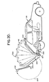
- FIGS 18-20 the presently preferred embodiment of the attachment 220 of the present invention for converting a standard type vehicle 40, such as the aforementioned "Volkswagen Rabbit" of Figure 2, into an expandable vehicle is shown.
- a standard type vehicle 40 such as the aforementioned "Volkswagen Rabbit" of Figure 2
- the attachment 220 is secured to the vehicle 40 its operation and function is essentially identical to that previously described with reference to Figures 1-12 with the exception of the rear bumper 222 arrangement which is stationary in the arrangement of Figures 18-20 and is preferably the standard type rear bumper provided with the vehicle 40.
- the attachment 220 preferably includes an extension shell 224, such as formed of molded plastic such as fiberglass or formed metal, which acts as the housing for accordion hood 46 and serves the same function in essentially the same manner as movable body portion 42a of Figure 2 except that it is separate from the balance of the vehicle body 40 until secured thereto in place of the standard rear body panel provided with the vehicle 40.
- an extension shell 224 such as formed of molded plastic such as fiberglass or formed metal, which acts as the housing for accordion hood 46 and serves the same function in essentially the same manner as movable body portion 42a of Figure 2 except that it is separate from the balance of the vehicle body 40 until secured thereto in place of the standard rear body panel provided with the vehicle 40.
- the accordion hood 46 is preferably identical with that previously described with reference to the embodiment of Figure 2 and will not be described in greater detail hereinafter.
- extension shell 224 The physical dimensions of the extension shell 224 are preferably chosen so as to mate with the existing body opening provided in the vehicle 40 to be converted into an expandable vehicle, such as the rear body panel thereof, so as to facilitate replacement of the standard rear body panel with the attachment 220 of the present invention.
- extension shell 224 preferably contains a storage compartment 226 including a hood storage trough for the collapsed hood 46 ( Figure 19) for storing the collapsed hood 46 while allowing the vehicle to remain substantially unchanged with respect to existing windows and doors, and even more importantly, only minimally, at worst, affects the nor- mall y provided interior room of the vehicle.
- extension shell 224 subsequently defines a half volume for the original enclosed volume.
- this panel 230 is preferably reconnected to extension shell 224 in a conventional hinged 234 manner similar to a hatchback to allow panel 230 to pivot open and closed, as shown in Figure 20, in a normal manner.
- extension shell 224 which corresponds to the standard size opening normally closed by panel 230 when it is part of vehicle 40, with opening 232 being surrounded by the normally required sealing gaskets 240 which conventionally weatherproof the opening 232 when panel 230 is in the closed position.
- the extension shell 224 is designed to interface with the vehicle body 40 conformations, moldings and conventional seating gaskets 242 in a manner to make it stable, waterproof and function as an integral part of the vehicle 40 when secured thereto.
- extension shell 224 is preferably attached to the existing bolts 250 for attachment of bodywork to the vehicle 40 chassis.
- the standard bumper 222 supplied with the vehicle 40 preferably remains in its standard location in both the open and closed positions of extension shell 224 which is shaped to enable this. If necessary, however, the bumper mountings may be extended to locate the bumper 222 a greater distance from the vehicle body 40, if required.
- Figure 20 illustrates the standard rear window hatch panel 230 in the fully open position (via path 260) to allow entrance and egress to the expanded volume provided by hood 46. It should be noted that panel 230 also functions in its normal manner in the closed position of hood 46 and shell 224 to permit access to the rear storage compartment of the vehicle 40 and to provide a rear view.
- the standard rear window hatch panel 230 which was removed from its original hinged location on vehicle 40 is shown reinstalled (illustrated by arrow 270) on expandable extension shell 224 which, in turn, mates (illustrated by arrow 272) with the standard rear opening gaskets 242 with new conventional gasketing preferably being applied where extension shell 224 overlaps the roof 274 of the vehicle 40.
- the piece 280 of the standard rear body paneling supplied with the vehicle 40 which contains the tail lights is removed and then reinstalled in the extension shell 224 after installation of shell 224.
- extension shell 224 After completion of the attachment of extension shell 224 and its associated components to the vehicle body 40, preferably the arrangement, except for the bumper arrangement, functions identically to that previously described with reference to the embodiment of Figure 2. Thus, its operation will not be described in any greater detail. Suffice it to say that other types of attachments can be made for other type vehicles, such as vans, etc., to convert such vehicles into expandable type vehicles without departing from the present invention.
- Expanded vehicles in accordance with the present invention will find uses in the fields of education, recreation, medical assistance and creative arts, as well as in the military.
- autonomous type vehicle is meant to include cars of all types, vans and campers.
Landscapes
- Engineering & Computer Science (AREA)
- Health & Medical Sciences (AREA)
- Public Health (AREA)
- Transportation (AREA)
- Mechanical Engineering (AREA)
- Body Structure For Vehicles (AREA)
- Superstructure Of Vehicle (AREA)
Abstract
Description
- The invention relates to an expandable vehicle of the type comprising a vehicle body defining an outer configuration for the vehicle and comprising a movable panel member and a stationary body frame as well as means for joining said movable panel member to the stationary body frame, said means comprising pivotable links and a collapsible hood, the movable panel member being pivotable about a pivot axis through an angle of substantially 90° from a closed position, into which confrontable edges of said panel member and said body frame confront each other, into an open position in which the hood is expanded to provide an enclosed enlarged usable volume.
- An expandable vehicle of the above type is known from GB-A-1 196 077. This prior art expandable vehicle shows drawbacks in so far as there is no increased headroom established when the movable body panel member is in its open position. This is disadvantageous in so far that even in the extended condition one is unable to stand or stoop comfortably within the expanded volume. In particular, the highest point of the expandable vehicle according to GB-A-1 196 077 in the open condition of the hood is not higher than the highest point of the originally enclosed volume as defined by the vehicle roof.
- The invention as claimed is intended to provide a remedy. It solves the problem of how to design an expandable vehicle, in particular an automotive vehicle, where the expanded volume has an increased headroom whilst providing a total enclosed expanded volume in said open position, greater than twice that of the original enclosed usable volume in said closed position.
- The advantages offered by the invention are mainly that an increased headroom is provided which makes the inventive vehicle suitable for usage in the fields of education, recreation, medical assistance and creative arts, as well as for military use.
- Ways of carrying out the invention are described in detail below with reference to drawings which illustrate two specific embodiments, in which:
- Figures 1A to 11 are diagrammatic illustrations, in perspective, of the basic underlying geometric concepts upon which the present invention relies;
- Figure 2 is a side elevational view of an expandable compact car, illustrating the vehicle in the closed or unexpanded configuration thereof;
- Figure 3 is a side elevational view of the vehicle of Figure 2 in the open or expanded configuration thereof;
- Figure 4 is a fragmentary cut-away perspective view as shown in Figure 3;
- Figure 5 is a partially exploded fragmentary cut-away perspective view of the vehicle as shown in Figure 2;
- Figure 6 is a fragmentary perspective detailed view of the vehicle as shown in Figure 2, illustrating the impact load transferring arrangement between the rear bumper and the main body panels;
- Figure 7 is a fragmentary perspective sectional detailed view of the hinge at the point of the rear bumper mount of the impact load transferring arrangement of Figure 6;
- Figure 8 is a perspective fragmentary detailed view of another portion of the vehicle as preferred of Figure 2;
- Figure 9 is a sectional view taken along the line 9-9 in Figure 8;
- Figure 10 is a perspective view of a folding hood and hood support members in accordance with the invention, such as for use with embodiment of Figure 2;
- Figure 11 is a partial perspective view of the folding hood and hood support members of Figure 10 in a folded position;
- Figure 12 is a sectional view taken along line 12-12 in Figure 5.
- Figure 13 is a perspective view of another automobile type vehicle, and particularly a van, in the open or expanded configuration;
- Figures 14A-14C are rear elevational views of the vehicle of Figure 13 illustrating three stages of expansion from closed, to partially open, to fully open, respectively;
- Figure 15 is a perspective view of a preferred motor drive unit for opening and closing the hood of the embodiment of Figure 13;
- Figure 16 is a diagrammatic illustration of the geometry of the drive motor and threaded rod of the embodiment of Figures 14A-14C and 15 during opening and closing;
- Figures 17A-17E are diagrammatic illustrations of the support stand for the side panel of the embodiment of Figures 14A-14C and 15 as the moving panel moves between the open and closed positions;
- Figure 18 is an exploded side elevational view, similar to Figure 2, illustrating a standard type automobile, and particularly a compact car, for converting it into an expandable type vehicle;
- Figure 19 is an exploded perspective view, similar to Figure 18 of the embodiment of Figure 18; and
- Figure 20 is a side elevational view of the embodiment of Figure 18 showing the attachment mounted to the vehicle and being in the open or expanded configuration thereof.
- Referring initially to Figures 1 A, 1B and 1 C the basic underlying geometric principals upon which the present invention is based are illustrated. The basic underlying concept of the present invention, as explained below, may be understood by representations of a cubic or rectangular volume which is intersected by an imaginary plane diagonally from corner to corner so that the volume is bisected.
- Figures 1 A-1 C refer to various stages of the same embodiment as it moves from a closed position (Figure 1A) to an open position (Figure 1C). Figure 1A illustrates a
rectangular compartment 10 such as would be enclosed by an automobile type vehicle, such as a car or van, thecompartment 10 being bisected by an imaginarydiagonal plane 11 which includesedges plane 11 defines twocompartment portions 12a, 12b within thecompartment 10 whichcompartment 10 is shown in the closed position in Figure 1 A. As shown in Figures 1 B and 1 C, if thecompartment portions 12a, 12b are hinged to one another for pivotal movement about theedge 14, and are otherwise separated from one another along a line of separation defined by the intersection of theplane 11 with thecompartment 10 to provide a pair of half volumes, it is possible to provide an expanded enclosed volume by way of an according folding hood covering 18 by rotation of one of the half volumes 12a approximately 90° about one of the two edges common to both half volumes. Thehood 18 is joined at opposite ends thereof to confrontingedges 20a, 20b ofcompartment portions 12a, 12b, respectively. Whencompartment 10 is in the fully opened or expanded configuration as shown in Figure 1 C, the top of thehood 18 defines or circumscribes a circular arc terminating along the furthest separated edges ofcompartment portions 12a, 12b. It can be shown that if the original volume is a cube, the ratio of volumes enclosed bycompartment 10 when in its expanded or open configuration (Figure 1 C) as compared to its closed configuration (Figure 1A) is 2.54 to 1 or an increase in volume of 154%. In addition, the arch described by the top ofhood 18 creates an increased headroom for the enclosed expanded volume as shown in Figure 1 C by thedotted line 9 which represents the original headroom. This idea of providing such a relatively large increase in the normally enclosed volume of a compartment such as 10 while also increasing the headroom such as illustrated in Figures 1A-1 C, is the main gist of the present invention. The basic concept as illustrated in Figures 1A-1C gives rise to other structural techniques for expanding a compartment of given spatial volume to an expanded enclosure having more than twice the given volume by use of an accordion folding hood such as 18. - Thus, for example, Figures 1 D-1 F illustrate a
compartment 20 which, instead of being separable into two compartments defined by a diagonal plane such as 22, has oneportion 24a which in profile has a "dog leg" bend.Portion 24a is joined for relative pivotable movement to theremaining portion 24b alongedge 26. Anaccordion folding hood 28 is joined at opposite ends thereof to confrontingedges 30a, 30b on theseparable compartment portions accordion hood 28 being arranged to fold over at the "dog leg"bend 27 whencompartment portion 24a is swung into closed confronting relationship withportion 24b as in Figure 1D - The arrangement of Figures 1 D-1 F has the advantage of providing a maximum vertical height H within the expanded compartment 20 (Figure 1 E) which is greater than the length of
diagonal line 29 defined by imaginary plane 22 (Figure 1 D), whereas the expandedcompartment 10 of Figures 1A-1C has a maximum vertical height which is determined by the length ofdiagonal 31. The expandedcompartment 20 thereby has an even greater percentage volume increase over its unexpanded volume than the increase obtained by expanding thecompartment 10 of Figures 1 A-1 C. Further, because the line of separation between thecompartment portions diagonal line 29, a passageway including a door leading into and out ofcompartment 20 may be easily located on the end wall ofcompartment portion 24b without interference from diagonally disposed hood support members as would be encountered in connection with thefolding hood 18 as it is embodied withincompartment 10 of Figures 1A-1C. - Another
expandable compartment 30 is shown in Figure 1G-11. The volume enclosed by the expandedcompartment 30 as in Figure 11 is also substantially greater than the volume within closedcompartment portions 32a, 32b . in Figure 1G. Compartment portions 32a, 32b are joined to each other for relative pivotal movement about anaxis 34 which is in the vicinity of and substantially parallel to the outside lower right edge ofcompartment 30. A passageway may also be provided on the endwalls of thecompartment portion 32b without interference from any supporting structures for thefolding hood 36. - While the basic concept of the present invention as set forth above and illustrated in Figures 1A-1C, 1D-1F and 1G- 1 has been explained with regard to three particular
expandable compartments - A
vehicle 40 such as the standard 1977 Volkswagen Rabbit appears in Figure 2 in an unexpanded, normal running configuration, and in Figures 18-20 as modified according to the present invention. The preferred expansion technique applied to thevehicle 40 most closely resembles that shown and described above in connection with Figures 1 D-1 F. Thus, a generally "dog leg"shaped body portion 42a is joined for relative pivotal movement to theremaining vehicle body 42b by ahinge assembly 44 having an axis substantially parallel to and in the vicinity of the lower rear edge of thevehicle 40. It will be seen that theunexpanded vehicle 40 of Figure 2 is preferably nearly identical in profile to the conventional vehicle as it appears before modification according to the invention, except for a relatively slight bulge extending from the mid-roof line down across the back of thevehicle 40, owing to the generally "dog leg" shape of the separablemovable body portion 42a. - Generally speaking, the
expandable vehicle 40 shown in Figures 2 and 3 will preferably undergo only minor variation regarding the usable interior space occupied within the vehicle before it is modified in accordance with the present invention, i.e. the standard production automobile. - Such minor variations preferably include, by way of example;
- (a) modification of the rear seat to allow forward folding of both the
bottom cushion 62 and theseat back 64 to form a leveled platform (Figure 3); - (b) an approximate two inch reduction in head room above the rear seat due to the presence of a hood storage compartment (Figure 5);
- (c) an approximate five inch intrusion on either side of the standard vehicle into the rear storage/luggage compartment owing to the presence of the hood storage compartment (
Figurs 5 and 12); - (d) the addition of an approximately one inch thick foam plastic folding pad, preferably stored in the rear storage/luggage compartment for the purpose of providing a sleeping surface to be used inside the vehicle when expanded; and
- (e) a modified
panel 54 in the rear storage/luggage compartment which folds towards the rear when the vehicle is expanded in order to provide support for the sleeping pad (Figure - Assuming that the
vehicle 40 is the aforementioned standard 1977 "Volkswagen Rabbit", which is a compact car, and which is modified according to the present invention,vehicle 40 can be expanded to provide an enclosed, hooded sleeping surface which is, by way of example, six feet (182.9 cm) in length and three feet, four inches (101.6 cm) wide at the narrowest point betweenwheel wells 84 as shown in Figure 4. The maximum height of the expandedaccordion hood 46 as shown in Figure 3 is four feet, six inches (137.2 cm) above the sleeping surface. - The rear body panel and a portion of the rear side panel of the standard vehicle are preferably modified to accommodate the required storage compartment for the
accordion hood 46, with the details of the storage compartment being set out below in connection with Figures 5 and 12. - The standard rear panel and a portion of the rear side panel of the original vehicle are replaced by
movable body portion 42a which can be constructed of fiberglass, for example, and would be only slightly larger in height and width than the combined original equipment panels. Further, the confronting edges 48a ofpanels 42a should preferably accommodate weather proofing seals which may be conventional and are therefore not shown in the drawing, the seals being arranged to compress against corresponding confrontingedges 48b of vehicle body orstationary body frame 42b to form a weather tight seal whenbody portion 42a is securely closed againstvehicle body 42b as shown in Figure 2. - It will therefore be appreciated that the use of the preferred vehicle expansion technique as shown and described in connection with Figures 1 D-1 when applied to the body structure of a conventional automobile type vehicle such as the 1977 "Volkswagen Rabbit" in which the
movable body panel 42a subsequently defines a half volume for the original enclosed volume, allows the vehicle to remain substantially unchanged with respect to existing windows and doors and, even more importantly, only minimally, at worst, affects the normally provided interior room of the vehicle. - Figure 3 illustrates some of the basic structure associated with the expansion of
vehicle 40 from the normal running configuration shown in Figure 2. Specifically,accordion folding hood 46 is joined at opposite ends thereof in the vicinity of confrontingedge 48a, 48b, to themovable body portion 42a, and thevehicle body 42b, respectively. Theaccordion folding hood 46 preferably has pleatedfolding sections 50 arranged between associated-hood support members 52, thesupport members 52 being shown and described in further detail in connection with Figures 4, 5 and 8-11. - Also shown in Figure 3 is the sleeping
pad support panel 54 mentioned above, thepanel 54 being preferably hinged at 56 for relative pivotal movement of itsrearward portion 58 with respect to itsforward portion 60. Theforward portion 60 ofpanel 54 preferably rests horizontally across shiftedrear seat 62 and folded rear seat back 64, and extends back through the rear luggage/storage compartment ofvehicle 40.Rear bumper 66 onvehicle 40 is mounted for pivotal movement with respect to thevehicle 40 about an axis which substantially coincides with the axis ofhinge assembly 44, thebumper 66 being arranged to move in unison with themovable body portion 42a, as detailed later in connection with Figures 6 and 7. - Also shown in Figure 3 is a pivoted locking and
support brace 68 which is preferably provided and joined at its ends to thebody portion 42a and thevehicle body 42b, respectively, as shown. Further, if desired,rear window glass 70 may be hinged as at 72 to allow theglass 70 to swing out and away from the rear end of the sleepingpad support panel 54, should an occupant desire to open theglass 70 when using the expandedvehicle 40 in its expanded configuration. - An interior view of the
vehicle 40 as expanded in Figure 3 is given in Figure 4. Theaccordion folding hood 46 and other portions of thevehicle 40 are omitted for purposes of clarity. In Figure 4,hood support members 52 are shown in their expanded configuration, pivotally separated from one another about an axis which substantially coincides with the axis ofhinge assembly 44. - Regarding
hood support members 52, each of themembers 52 preferably has a hinged joint 80, described and shown in further detail in Figures 10 and 11. Thejoints 80 allow the upper portions of each of thehood support members 52 to preferably fold sideways in unison with the folding hood (unshown) and into a hood storage compartment which is shown and will be described in greater detail in connection with Figures 5 and 12. - A
sleeping pad 82 is shown in Figure 4 as preferably placed oversupport panel 54, therear portion 58 of thepanel 54 preferably being swung out to occupy the rear of the expanded compartment invehicle 40. As noted earlier, the narrowest portion of the sleeping pad 82 (and support panel 54) is defined by the distance betweenwheel wells 84, this distance being approximately three feet, four inches (101.6 cm) wide for the 1977 "Volkswagen Rabbit". - In Figure 5, a preferred arrangement is shown in which
folding hood 46 is collapsed into thehood storage compartment 86 preferably defined in part by a "U"-shaped channel.Compartment 86 is preferably contiguously joined to and extends from confrontingedge 48b of thevehicle body 42b within the interior of thevehicle 40.Body portion 42a is illustratively shown in Figure 5 as being rearwardly exploded away from the vehicle body:42b for purposes of clarity. As shown in Figure 5,hood storage compartment 86 preferably has a generally flattened "U"-shaped cross section of sufficient width to accommodatehood 46 when folded in unison with its associatedsupport members 52, themembers 52 preferably collapsing adjacent one another to define an essentially flat row ofcollapsed support members 52 within thecompartment 86 as shown in Figure 5. - The "U"-shaped compartment is contiguously joined to and follows the "dog leg" contour of the confronting edge of
vehicle body 42b. Thecompartment 86 therefore extends inwardly and across the top of the rear luggage/storage compartment of thevehicle 40. The lower ends of thechannel 86 are joined to the lower interior body portion of thevehicle body 42b as shown in Figure 5. - Preferably joined to the interior surface of
body portion 42a is ahood compartment cover 88 which is shaped to accommodate portions of thefolding hood 46,hood support members 52 and support member hinge joints 80 which may extend up above thecompartment 86 after thehood 46 is collapsed and stored therein upon movement of thebody portion 42a to its closed configuration. - Also shown in Figure 5 is a portion of the
hinge assembly 44, this assembly being shown in further detail in Figures 6, 8 and 9. As may be seen generally in Figure 5, hingeassembly 44 in addition to its normal function of joining thebody portion 42a to thevehicle body 42b for relative pivotal movement, acts to pivot each of thehood support members 52, the ends of each of thesupport members 52 being connected for said pivotal movement about the axis ofhinge assembly 44 in the vicinity of each end of thehinge assembly 44 as shown in Figure 5. - The
movable body portion 42a is shown in Figure 5 as exploded away from thevehicle body 42b merely for purposes of clarity, with the lower end ofbody portion 42a in actuality being joined to thevehicle body 42b for relative pivotal movement preferably by joining the lower edge of thebody portion 42a for pivotal movement about the axis ofhinge assembly 44, this construction is shown in detail and discussed later in regard to Figures 6-9. - Two
openings 90 are preferably provided through thebody portion 42a in the vicinity of the lower left and right sides thereof, respectively, and are preferably dimensioned to allow conventional typebumper shock absorbers 92 to pass therethrough. Theseshock absorbers 92 are shown in Figures 6 and 7 and will be described in greater detail in connection therewith. - Figures 6 and 7 illustrate the pertinent portions of the preferred arrangement for the
hinge assembly 44 and rear body panel ormovable portion 42a which is designed to transfer impact loads from therear bumper 66 of the vehicle through thehinge 44 to themain body panels 42b during normal use, whenhood 46 is closed (Figure 2) while also enabling the pivotal movement ofportion 42a and the subsequent opening ofhood 46 to provide the increased enclosed volume (Figure 3). Thus, Figure 6 illustrates portions ofmovable portion 42a,vehicle body 42b, andbumper 66, which hasshock absorber assemblies 92 extending sideways therefrom at both of its ends, which cooperate to provide the aforementioned preferred arrangement. The lower end portions of thehood support members 52 are also illustratively shown in Figure 6, with each of thesupport members 52 having aboss 94 at its lower end for pivotally engaging arod 96 which extends axially through thehinge assembly 44. As also shown and preferred in Figure 6, aclosing assist spring 98 is preferably disposed along and concentrically about thehinge assembly 44, with thespring 98 preferably acting to assist movement of thebody portion 42a towards the closed position (Figure 2) during such movement, such as by hand, of thebody portion 42a to help facilitate such closure. Further details regardlngspring assembly 98 and its mounting in relation to thebody portion 42a,vehicle body 42b and hingeassembly 44 are discussed below in regard to Figures 8 and 9. - Referring now to Figure 7,
rear bumper 66 and its manner of mounting to therear panel 42a and hingeassembly 44 to facilitate the aforementioned preferred arrangement is shown in section. As shown and preferred in Figure 7,bumper 66 is mounted to the plunger end of theshock absorbers 92, with the other end of theshock absorbers 92 preferably being joined to hingeassembly 44 for pivotal movement about therod 96. Thus, when thebody portion 42a is in its closed position (Figure 2)bumper 66 assumes its normal orientation at the rear ofvehicle 40 and impact loads from thebumper 66 are transferred through thehinge assembly 44 to the vehicle body ormain body panels 42b. As also shown and preferred in Figure 7, arubber pad 93 is provided at the junction point between the two opposinghalves hinge assembly 44. In addition, as illustrated by Figures 3 and 7 thehinge assembly 44 is also preferably designed to allow thebumper 66 to rotate outward and down as the rear hingedpanel 42a is moved to its open or expanded position (Figure 3). - From the foregoing description of the
expandable vehicle 40, it will be apparent that all of the component members thereof which move whenvehicle 40 is either placed in its open or expanded configuration or brought back to its closed or normal running configuration are each preferably pivoted about the same axis, i.e. therod 96 running throughhinge assembly 44. Thus, hingeassembly 44 provides a pivotal axis for thebody portion 42a which swings out from thevehicle body 42b, and also preferably provides the same axis by way ofrod 96 for each of thehood support members 52. - Referring now to Figure 8, a perspective view of
hinge assembly 44 as viewed from the rear left side ofvehicle 40 is. shown. Movable body portion orrear panel 42a is omitted from Figure 8 for purposes of clarity; however, its connection to thehinge assembly 44 will be described below. - A
second hinge assembly 44, which is not shown in Figures 8 and 9, is preferably mounted at the rear right side ofvehicle 40 in such a way that thebosses 94 ofhood support members 52 which are opposed to those shown in Figure 8 preferably engage asecond rod 96 disposed in thesecond hinge assembly 44 in the same manner as those shown in Figure 8. The components which comprise thesecond hinge assembly 44 are therefore preferably identical to those described herein in connection withhinge assembly 44 in Figures 8 and 9, with thesecond hinge assembly 44 preferably being mounted in the vicinity of the right rear side ofvehicle body 42b in substantially axial alignment and in a 180° orientation with respect to thehinge assembly 44 shown in the drawing. - As further shown and preferred in Figures 8 and 9, a
channel member 100 is joined along one side thereof to a lower rear body portion of vehicle body orstationary body frame 42b.Channel member 100 is preferably U-shaped and disposed transverse to the longitudinal axis ofvehicle 40 at a location proximate to the lower rear edge ofvehicle 40. Aconventional rubber boot 101 is also preferably provided to extend at one end thereof from beneathchannel member 100 to joint to themovable body portion 42a for providing weather sealing. - In the preferred embodiment, hinge
assembly 44 is fixedly joined tochannel member 100 preferably by way ofbushings support rod 96 in proper alignment.Bushing 104 is also provided aboutaxle rod 96 for smooth rotational movement therearound, and is fixedly joined by way of itsflange 105 tomovable body portion 42a (not shown). In addition, one end ofspring 98, as shown and preferred in Figures 8 and 9, extends out through a vertical slotted opening 107 on the left side ofbushing 102, and engages themovable body portion 42a, while the other end ofspring 98 is fixedly secured as by projecting throughopening 108 onstationary bushing 102. - Turning now to further details of the
accordion folding hood 46 andhood support members 52, reference will be made to Figures 10 and 11.Accordion hood 46 is preferably constructed of very light weight fabric which is tight woven so as to shed water but which can still breathe, an example being tenting nylon. Thehood 46, shown in a partially expanded position in Figure 10, preferably has pleatedfold sections 50 arranged between adjacent upper portions of thehood support members 52, with thesupport members 52 each being preferably joined to thehood 46 about its outer surface so as to cause thepleated sections 50 ofhood 46 to fold inwardly when thesupport members 52 are collapsed as explained below. - In order to allow the
folding hood 46 to be folded for storage withinstorage compartment 86 on thevehicle body 42b, a foldable, preferably pleated,fabric strip 110 is provided along the sides of thehood 46, as shown in Figure 10, thestrip 110 following a path which lies adjacent each of the hoodsupport pivot joints 80 whereat thehood material 46 preferably becomes folded when the upper portions of the hood support members are swung down into thestorage compartment 86.Fabric strip 110 is preferably a hypalon coated stretch fabric, or its equivalent, having sufficient characteristics to withstand the folding stresses imparted thereto by the folding joints 80. Thus, for example,strip 110 may comprise an elastomeric membrane instead of the aforementioned stretch fabric. - Referring now to Figure 11, hinge joints 80 are shown in a folded over position, with the associated
hood support members 52 being collapsed towards one another. It is preferred that each of the hinge joints 80 be of such construction as to swing the upper portions ofhood support members 52 through an arc of about 75° to accommodate the preferred "dog leg" bend for the embodiment of Figure 2 which bend is defined by the confrontingedge 48b andstorage compartment 86 onvehicle body 42b. When thehood 46 is brought to its expanded configuration, it is preferred that hinge joints 80 each have locking means thereon for maintaining each of thehood support members 52 in a straight line thereby providing additional stability to the expandedhood 46. For example, each of the hinge joints 80 may preferably comprise astainless steel hood 112 havingdimples 114 thereon, with thedimples 114 gripping around the edge of astainless steel shank 116 to steadily maintain the movable upper portions of thesupport members 52 in alignment with the lower straight portions thereof. Theshank 116 is preferably mounted withinstainless steel hood 112, such as by apivot pin 118 which engages registered openings provided throughstainless steel hood 112 andshank 116. Thus, as the upper portions ofhood support members 52 are swung down intostorage compartment 86, thedimples 114 are forcedpast shanks 116 to thereby spread the sides ofstainless steel hood 112 apart until thedimples 114 are moved past the opposite side of theshank 116. - Referring now to Figure 12, the
hood 46storage compartment 86 is preferably contiguously joined to thevehicle body 42b in the vicinity of its confronting edge 43b. Similarly, thecomplimentary hood 46storage compartment 88 is preferably joined to themovable body portion 42a in the vicinity of its confronting edge 48a. Thecompartments folding hood 46 being enclosed within them. - The aforementioned confronting edge 48a of the
movable body portion 42a is preferably formed with a concave lip as shown in Figure 12, and agasket 120 is preferably sealed against the concaved lip surface. A weather proof seal is thereby provided when themovable body portion 42a is brought to the closed position (Figure 2), thegasket 120 then preferably being compressed against areglet 122 mounted on the exterior ofvehicle body 42b in the vicinity of its confrontingedge 48b. As also shown and preferred in Figure 12, theaccordion folding hood 46 is joined at its opposite ends to the interior surfaces of body portion orrear panel 42a andvehicle body 42b, for example, by way of molding strips 124, 126, respectively. Further, thecomplimentary compartments edges movable body portion 42a is closed. Of course, although it is presently preferred, it is not necessary that edges 128 and 130 abut one another, the weather proof seal which is provided bygasket 120 andreglet 122 being of greater importance for purposes of such sealing. - The
expandable vehicle 40 in the embodiment of Figure 2 described above with reference to Figures 2-12, is preferably capable of being placed in an open or expanded configuration simply by hand, with the movable body portion orrear panel 42a being maintained in its expanded position preferably by way of thesupport brace 68 shown in Figure 3. Similarly, movement of thebody portion 42a back to its closed or unexpanded position may also be easily carried out by hand, with a torsional assist preferably being provided by way of the closing assist springs 98 detailed in connection with Figure 9, or by such other conventional torsional assist mechanism as may be provided. Such ability to accomplish the above by hand becomes particularly important where size and weight are critical factors, such as in the instance of a compact car. - When in its closed position, the
body portion 42a is preferably securely joined to thevehicle body 42b such as by a conventional manually operated latching mechanism or other such means which, being conventional, are not shown in the drawing. The latching mechanism, such as used in conventional "hatchback" automobiles, also operates to maintain a tight compression seal between thereglet 122 extending proximate the confrontingedge 48b of thevehicle body 42b, and thegasket 120 which extends about the confronting edge 48a of themovable body portion 42a. As explained above, such a seal is preferably required to insure weather proofing of the interior of the'vehicle 40 when in its normal running configuration (Figure 2). - If desired, however, if size, weight and expense are not critical, an electrically operated drive mechanism may be used for opening and closing the
movable body portion 42a, such as the drive mechanism to be described in greater detail with reference to the van type ofautomobile type vehicle 140 to be described hereinafter with reference to Figures 13, 14A-14C, 15, 16 and 17A-17E. - With respect to Figures 13, 14A-14C, 15, 16 and 17A-17E, the basic underlying concept upon which the present invention is based may be applied to any type of automobile type vehicle if desired, with the embodiment shown in these figures being directed to modification or use in a standard van type of vehicle, such as a 1977 "Volkswagen Van". In particular, Figures 13 and 14A-14C illustrate such a
van type vehicle 140 having anexpandable accordion hood 144 attached to portions thereof in accordance with the present invention for increasing both the headroom and the usable enclosed volume of thevan 140. In Figure 13, theexpandable van 140 has a movable side body portion orpanel 142a, as opposed to rear body portion orpanel 42a of the embodiment of Figure 2, which is connected to thevan body 142b for pivotal movement about an axis substantially parallel to and in the vicinity of the lower left side edge of thevan 140. As will be described in greater detail hereinafter, the principles of operation of theexpandable van 140 are essentially identical to that previously described with reference to the embodiment of Figure 2 except for the preferred use of the electrically mounted drive mechanism due to the relative size and weight of themovable side panel 142a. Thus,accordion folding hood 144 is preferably joined at opposite ends thereof to thebody portion 142a and thevan body 142b, respectively. In the preferred embodiment of Figure 13, confronting edge 146a of themovable body portion 142a defines a "dog leg" bend (similar to the "dog leg" bend in the embodiment of Figure 2) so that, when thefolding hood 144 is in its open or expanded configuration, a relatively high vertical clearance or increased headroom will be obtained within the enclosed expandable compartment as compared to the height or headroom available within thevan 140 in its closed or unexpanded configuration. A series ofhood support member 148, each havinghinge joints 150 disposed on both sides thereof, allow thefolding hood 144 to be collapsed within ahood storage compartment 152 which is contiguously joined to thevan body 142b in the vicinity of its confrontingedge 146b. Further structural details with respect to the opening and closing of thehood 144 are preferably identical with those described with reference to the embodiment of Figure 2 with such modification as may now be readily apparent to one of ordinary skill in the art from the foregoing disclosure. Accordingly, such description will not be repeated herein. - As mentioned above in connection with the
expandable vehicle 40, it may sometimes be desirable to provide an electrical drive mechanism for opening and closing themovable body portion 42a. The use of such a drive mechanism is presently preferred in the embodiment of Figure 13 and will now be described below in relation to theexpandable van 140 shown therein. This mechanism can readily be adapted for use in combination with theexpandable vehicle 40, if desired. - Referring now to Figures 14A-14C, the
van 140 as it appears from the rear and is brought from a closed or unexpanded configuration (Figure 14A) through a partially open or expanded configuration (Figure 14B) to a fully open or expanded configuration (Figure 14C) is illustratively shown. Thus, as shown and preferred in Figures 14A-14C, and in more detail with reference to Figures 15 and 16, a pair of spaced apart conventionalelectric drive motors 153 are mounted for pivotal movement about an axis running horizontally lengthwise of the vehicle 140 (perpendicular to the drawing) as detailed further below in connection with Figures 15 and 16. Each of thedrive motors 153 and their associated interconnection to themovable body portion 142a is preferably identical, with only one such typical interconnection being described hereinafter. The pair ofmotors 153 are preferably located at each of the ends of themovable body portion 142a.Electric drive motor 153 preferably operates to threadably engage and move a threadedrod 154 through a correspondingly threaded bore within the rotor ofmotor 153, one end of therod 154 being pivotally connected to asidewall 156 of themovable body portion 142a at 158. It will be understood that the respective locations of themotor drive units 153, the pivotal connection points 158 and the overall length of the threadedrod 154 must be suitably chosen so that when thevehicle 140 is in its closed configuration (Figure 14a) the unconnected end of therod 154 will lie wholely within thehood storage compartment 152, or within some other portion at the top of thevehicle 140 without interference by any part of the body structure thereof. - As mentioned above,
motor unit 153 has a threaded bore extending through the rotor thereof, with the threads in the bore engaging the corresponding threads on therod 153. Thus, as the rotor in themotor unit 153 is caused to rotate as by energization ofmotor unit 153 by an outside electrical source, threadedrod 154 is moved forward or backward with respect to themotor unit 153, depending upon the sense of rotation of the rotor. As further shown and the preferred in Figure 15, one end of therod 154 is pivotally connected at 158 to themovable body portion 142a of thevan 140 so as to raise or lower thebody portion 142a depending upon the sense of rotation of themotor 153. A collapsibleplastic tube 164 is preferably provided between thepivot point 158 and themotor 153 along the length of therod 154, so as to protectrod 154 from weather elements whenvehicle 140 is in its expanded configuration androd 154 is fully extended out from the side of thevehicle 140. As also shown and preferred in Figure 15, themotor unit 153 is mounted on astructural flame 162 for providing free pivotal movement - of the
motor unit 153 about an axis substantially parallel to the pivotal axis provided forbody portion 142a, owing to the fact that the threaded rod 1 54 will urge themotor unit 153 to swing about such an axis as thebody portion 142a is raised or lowered. Thus, for example, anopen housing 165 may be defined along the length of theframe 162, and themotor unit 153 be mounted for such free pivotal movement withinhousing 165 as by apivotal connection 168 at both sides of thehousing 165. - Summarizing the above, Figure 16 is a diagrammatic illustration of the preferred geometry of the
drive motor 153 and threadedrod 154 during opening and closing of themovable body portion 142a of thevan 140. Thus, as stated above, themotor 153 is mounted in a manner which allows it to pivot as the threadedrod 154 passes through an arch while opening or closingmovable body portion 142a with the path of therod 154 during such opening and closing being indicated by the dotted line havingreference numeral 170 in Figure 16 and with the path of the end of therod 154 during such opening and closing being indicated by the dotted line havingreference numeral 172 in Figure 16. In this regard, it should be noted that the position of the threadedrod 154 whenmovable body portion 142a is closed preferably corresponds to the angle ofaccordion hood 144 storage. The aforementioned electric drive mechanism 153-154 thus serves to push open theside 142a of thevan 140 to the expanded position (Figure 14C) as well as to lift the movingside 142a shut into its closed position (Figure 14A). In addition, it preferably serves to cinch shut the movingside 142a which compresses theaccordion hood 144 into its closed position while also compressing weather seals (not shown) at the edges of the movingside 142a to allow the main closing latch (not shown) to be fastened. - As shown and preferred in Figures 14A-14C and particularly in Figures 17A-17E, a pair of hinged supports stands 160 are preferably provided on the outside wall of the
movable body portion 142a, with each stand 160 preferably sliding flush against the outside wall (see Figures 17A and 17E) when thevan 140 is in the closed position (Figure 14A). Thus, as shown and preferred in Figures 17A17E, as the movingpanel 142a is lowered into the open position (Figures 14A and 17A) through the various partially open positions (Figures 14B and 17B), the support stand 160 swings down into the fully open position shown in Figures 14C, 17C and 17D.Support stand 160 preferably works by gravity and is moved into place as the weight of theweighted support foot 180 falls downward. As thefoot 180 touches the ground it preferably lifts the slidingbraces toothed track panel 142a settles onto thefoot 180 and, along with a pivotally mounted fixed hinge third brace 160c forfoot 180, maintain a rigidtriangular brace 160a-160b-160c. Upon closing, a similar reverse procedure occurs which is conventionally assisted by means of a counterweight 184 (Figure 17D). - Referring now to Figures 18-20, the presently preferred embodiment of the
attachment 220 of the present invention for converting astandard type vehicle 40, such as the aforementioned "Volkswagen Rabbit" of Figure 2, into an expandable vehicle is shown. As will be described in greater detail, once theattachment 220 is secured to thevehicle 40 its operation and function is essentially identical to that previously described with reference to Figures 1-12 with the exception of therear bumper 222 arrangement which is stationary in the arrangement of Figures 18-20 and is preferably the standard type rear bumper provided with thevehicle 40. Suffice it to say, theattachment 220 preferably includes anextension shell 224, such as formed of molded plastic such as fiberglass or formed metal, which acts as the housing foraccordion hood 46 and serves the same function in essentially the same manner asmovable body portion 42a of Figure 2 except that it is separate from the balance of thevehicle body 40 until secured thereto in place of the standard rear body panel provided with thevehicle 40. Thus, theaccordion hood 46 is preferably identical with that previously described with reference to the embodiment of Figure 2 and will not be described in greater detail hereinafter. The physical dimensions of theextension shell 224 are preferably chosen so as to mate with the existing body opening provided in thevehicle 40 to be converted into an expandable vehicle, such as the rear body panel thereof, so as to facilitate replacement of the standard rear body panel with theattachment 220 of the present invention. As in the arrangement of Figure 2 with respect tomovable body portion 42a,extension shell 224 preferably contains astorage compartment 226 including a hood storage trough for the collapsed hood 46 (Figure 19) for storing thecollapsed hood 46 while allowing the vehicle to remain substantially unchanged with respect to existing windows and doors, and even more importantly, only minimally, at worst, affects the nor- mally provided interior room of the vehicle. This results from the use of the preferred vehicle expansion technique as shown and described in connection with Figures 1 D-1 F in which extension shell 224 subsequently defines a half volume for the original enclosed volume. In this regard, after the standardrear window panel 230 is removed from thevehicle 40 prior to attachment ofextension shell 224 thereto, thispanel 230 is preferably reconnected toextension shell 224 in a conventional hinged 234 manner similar to a hatchback to allowpanel 230 to pivot open and closed, as shown in Figure 20, in a normal manner. Anopening 232 is preferably provided inextension shell 224 which corresponds to the standard size opening normally closed bypanel 230 when it is part ofvehicle 40, with opening 232 being surrounded by the normally required sealinggaskets 240 which conventionally weatherproof theopening 232 whenpanel 230 is in the closed position. As shown and preferred in Figure 18, theextension shell 224 is designed to interface with thevehicle body 40 conformations, moldings andconventional seating gaskets 242 in a manner to make it stable, waterproof and function as an integral part of thevehicle 40 when secured thereto. With respect to attachment of theextension shell 224 to thevehicle 40 stationary frame,extension shell 224 is preferably attached to the existingbolts 250 for attachment of bodywork to thevehicle 40 chassis. As shown and preferred in Figures 19 and 20, thestandard bumper 222 supplied with thevehicle 40 preferably remains in its standard location in both the open and closed positions ofextension shell 224 which is shaped to enable this. If necessary, however, the bumper mountings may be extended to locate the bumper 222 a greater distance from thevehicle body 40, if required. - Figure 20 illustrates the standard rear
window hatch panel 230 in the fully open position (via path 260) to allow entrance and egress to the expanded volume provided byhood 46. It should be noted thatpanel 230 also functions in its normal manner in the closed position ofhood 46 andshell 224 to permit access to the rear storage compartment of thevehicle 40 and to provide a rear view. - Referring once again to Figure 18, the standard rear
window hatch panel 230 which was removed from its original hinged location onvehicle 40 is shown reinstalled (illustrated by arrow 270) onexpandable extension shell 224 which, in turn, mates (illustrated by arrow 272) with the standardrear opening gaskets 242 with new conventional gasketing preferably being applied where extension shell 224 overlaps theroof 274 of thevehicle 40. It should be noted that preferably thepiece 280 of the standard rear body paneling supplied with thevehicle 40 which contains the tail lights is removed and then reinstalled in theextension shell 224 after installation ofshell 224. - After completion of the attachment of
extension shell 224 and its associated components to thevehicle body 40, preferably the arrangement, except for the bumper arrangement, functions identically to that previously described with reference to the embodiment of Figure 2. Thus, its operation will not be described in any greater detail. Suffice it to say that other types of attachments can be made for other type vehicles, such as vans, etc., to convert such vehicles into expandable type vehicles without departing from the present invention. - While specific embodiments of the present invention have been disclosed hereinabove, it will be understood that most kinds of vehicles can be modified or originally designed according to the teachings of the present invention. Thus, while a standard passenger automobile has been illustrated herein as modified according to the present invention in a predetermined manner, many other type vehicles may be similarly modified or designed, or the manner of modification may be varied, such as for example the rearrpanel as opposed to the side panel of a van could be movable to provide the expanded configuration of the types of arrangements illustrated by Figures 1 A-1 C and Figures 1 G-1 I could be employed instead of the arrangement of Figures 1 D-1 F.
- Expanded vehicles in accordance with the present invention, will find uses in the fields of education, recreation, medical assistance and creative arts, as well as in the military.
- Modifications and variations of an expandable vehicle or an attachment for providing such a vehicle in accordance with the present invention will be readily apparent to a worker skilled in the art.
- It should be noted that as used throughout the specification and claims, the term "automobile type vehicle" is meant to include cars of all types, vans and campers.
Claims (14)
Applications Claiming Priority (2)
| Application Number | Priority Date | Filing Date | Title |
|---|---|---|---|
| US05/845,541 US4132444A (en) | 1977-10-26 | 1977-10-26 | Expandable vehicle |
| US845541 | 1986-03-28 |
Publications (2)
| Publication Number | Publication Date |
|---|---|
| EP0007368A1 EP0007368A1 (en) | 1980-02-06 |
| EP0007368B1 true EP0007368B1 (en) | 1984-02-29 |
Family
ID=25295465
Family Applications (1)
| Application Number | Title | Priority Date | Filing Date |
|---|---|---|---|
| EP78900181A Expired EP0007368B1 (en) | 1977-10-26 | 1979-05-25 | Expandable vehicle |
Country Status (7)
| Country | Link |
|---|---|
| US (1) | US4132444A (en) |
| EP (1) | EP0007368B1 (en) |
| JP (1) | JPS6312012B2 (en) |
| CA (1) | CA1089507A (en) |
| DE (1) | DE2862382D1 (en) |
| IT (1) | IT1108389B (en) |
| WO (1) | WO1979000238A1 (en) |
Cited By (1)
| Publication number | Priority date | Publication date | Assignee | Title |
|---|---|---|---|---|
| DE102017206260A1 (en) * | 2017-04-11 | 2018-10-11 | Volkswagen Aktiengesellschaft | Vehicle roof and motor vehicle |
Families Citing this family (13)
| Publication number | Priority date | Publication date | Assignee | Title |
|---|---|---|---|---|
| EP0187430A1 (en) * | 1985-01-08 | 1986-07-16 | George Beggs | Attachment for converting a vehicle into an expandable vehicle |
| JPH02258438A (en) * | 1989-03-31 | 1990-10-19 | Suzuki Motor Co Ltd | Multi-purpose automobile |
| IT1277960B1 (en) * | 1995-12-22 | 1997-11-12 | Paolo Sbuelz | TENT STRUCTURE HOUSED IN CORRESPONDENCE TO THE REAR LOADING COMPARTMENT OF A VEHICLE AND ARTICULATED TO OPEN OUTWARDS |
| US5971459A (en) * | 1997-08-29 | 1999-10-26 | Gauthier; Gaston | Camper extension |
| US6474714B1 (en) * | 2001-05-11 | 2002-11-05 | Ernest R. Stettner | Convertible cargo body for a vehicle |
| DE10233746A1 (en) * | 2002-07-24 | 2004-02-12 | Webasto Vehicle Systems International Gmbh | Frame element for attachment in the lower region of the rear window of a vehicle and vehicle with such a frame element |
| US20040256873A1 (en) * | 2003-06-05 | 2004-12-23 | Mcmanus Patrick W. | Apparatus for configuring the cargo area of a vehicle |
| US8534735B2 (en) | 2003-06-05 | 2013-09-17 | The Riverbank, Llc | Apparatus for configuring the interior space of a vehicle |
| WO2008042085A2 (en) * | 2006-09-28 | 2008-04-10 | Nelson Charles R | Truck bed extender |
| KR101009648B1 (en) * | 2010-10-28 | 2011-01-24 | 김상오 | Folding mobile expansion house |
| DE102017210831B4 (en) * | 2017-06-27 | 2020-09-24 | Ford Global Technologies, Llc | Motor vehicle |
| CN109128504B (en) * | 2018-11-09 | 2020-12-04 | 湖北大冶汉龙汽车有限公司 | Method for preventing and solving laser welding defects of car body top cover |
| US11241994B2 (en) | 2019-10-10 | 2022-02-08 | Joseph Lee Pollon | Expandable vehicle |
Family Cites Families (4)
| Publication number | Priority date | Publication date | Assignee | Title |
|---|---|---|---|---|
| FR1422283A (en) * | 1964-11-10 | 1965-12-24 | Faure Bertrand Ets | Perfected living vehicle |
| US3420566A (en) * | 1965-10-20 | 1969-01-07 | Bart R Obra | Vehicle conversion |
| US4057284A (en) * | 1976-05-03 | 1977-11-08 | Paul Clifford Blank | Collapsible camper |
| US4065166A (en) * | 1976-08-26 | 1977-12-27 | Shoemaker Brian C | Demountable extension enclosure for motor vehicles |
-
1977
- 1977-10-26 US US05/845,541 patent/US4132444A/en not_active Expired - Lifetime
-
1978
- 1978-10-23 CA CA313,970A patent/CA1089507A/en not_active Expired
- 1978-10-25 DE DE7878900181T patent/DE2862382D1/en not_active Expired
- 1978-10-25 JP JP54500072A patent/JPS6312012B2/ja not_active Expired
- 1978-10-25 WO PCT/US1978/000119 patent/WO1979000238A1/en not_active Ceased
- 1978-10-26 IT IT69468/78A patent/IT1108389B/en active
-
1979
- 1979-05-25 EP EP78900181A patent/EP0007368B1/en not_active Expired
Cited By (1)
| Publication number | Priority date | Publication date | Assignee | Title |
|---|---|---|---|---|
| DE102017206260A1 (en) * | 2017-04-11 | 2018-10-11 | Volkswagen Aktiengesellschaft | Vehicle roof and motor vehicle |
Also Published As
| Publication number | Publication date |
|---|---|
| IT1108389B (en) | 1985-12-09 |
| WO1979000238A1 (en) | 1979-05-03 |
| JPS54500033A (en) | 1979-10-04 |
| IT7869468A0 (en) | 1978-10-26 |
| DE2862382D1 (en) | 1984-04-05 |
| CA1089507A (en) | 1980-11-11 |
| US4132444A (en) | 1979-01-02 |
| JPS6312012B2 (en) | 1988-03-17 |
| EP0007368A1 (en) | 1980-02-06 |
Similar Documents
| Publication | Publication Date | Title |
|---|---|---|
| US4223939A (en) | Attachment for converting a vehicle into an expandible vehicle | |
| US4027912A (en) | Collapsible roof-top camper | |
| CA1089507A (en) | Expandable vehicle | |
| US3865399A (en) | Auxiliary foldable step structure | |
| US4720133A (en) | Convertible top structure | |
| US3768855A (en) | Collapsible and expandable enclosure | |
| US3995890A (en) | Convertible structure | |
| US5735565A (en) | bedliner conversion unit for pickup truck | |
| US20020000732A1 (en) | Pick-up box extension | |
| US3622193A (en) | Collapsible camper | |
| US20030193211A1 (en) | Retractable top quarter window assembly | |
| US20080164722A1 (en) | Aerodynamic Drag Reducing Apparatus | |
| US3953066A (en) | Camper shell | |
| GB1572352A (en) | Vehicle body | |
| US4452465A (en) | Camping trailer and automobile-trailer combination | |
| US6439647B1 (en) | Folding camper for vehicle | |
| US3288521A (en) | Foldable alpha-frame trailer body | |
| US3398985A (en) | Motor vehicle body structure | |
| US4533171A (en) | Lift-roof trailer | |
| US4379583A (en) | Vehicle cabs having airflow deflectors on their roofs | |
| US12454168B2 (en) | Pickup truck add-on assembly and pickup truck | |
| EP0033648B1 (en) | Improvements relating to vehicle cabs having airflow deflectors on their roofs | |
| US2249273A (en) | Coach door construction | |
| US3343866A (en) | Collapsible trailer | |
| CN217532517U (en) | Pick-up car hopper installs subassembly and pick-up car additional |
Legal Events
| Date | Code | Title | Description |
|---|---|---|---|
| PUAI | Public reference made under article 153(3) epc to a published international application that has entered the european phase |
Free format text: ORIGINAL CODE: 0009012 |
|
| AK | Designated contracting states |
Designated state(s): DE FR GB |
|
| 17P | Request for examination filed |
Effective date: 19791031 |
|
| GRAA | (expected) grant |
Free format text: ORIGINAL CODE: 0009210 |
|
| AK | Designated contracting states |
Designated state(s): DE FR GB |
|
| REF | Corresponds to: |
Ref document number: 2862382 Country of ref document: DE Date of ref document: 19840405 |
|
| ET | Fr: translation filed | ||
| RAP2 | Party data changed (patent owner data changed or rights of a patent transferred) |
Owner name: MECHANICAL PLASTICS CORP. |
|
| PLBE | No opposition filed within time limit |
Free format text: ORIGINAL CODE: 0009261 |
|
| STAA | Information on the status of an ep patent application or granted ep patent |
Free format text: STATUS: NO OPPOSITION FILED WITHIN TIME LIMIT |
|
| 26N | No opposition filed | ||
| PGFP | Annual fee paid to national office [announced via postgrant information from national office to epo] |
Ref country code: GB Payment date: 19901012 Year of fee payment: 13 |
|
| PGFP | Annual fee paid to national office [announced via postgrant information from national office to epo] |
Ref country code: FR Payment date: 19901022 Year of fee payment: 13 |
|
| PGFP | Annual fee paid to national office [announced via postgrant information from national office to epo] |
Ref country code: DE Payment date: 19901130 Year of fee payment: 13 |
|
| PG25 | Lapsed in a contracting state [announced via postgrant information from national office to epo] |
Ref country code: GB Effective date: 19911025 |
|
| GBPC | Gb: european patent ceased through non-payment of renewal fee | ||
| PG25 | Lapsed in a contracting state [announced via postgrant information from national office to epo] |
Ref country code: FR Effective date: 19920630 |
|
| PG25 | Lapsed in a contracting state [announced via postgrant information from national office to epo] |
Ref country code: DE Effective date: 19920701 |
|
| REG | Reference to a national code |
Ref country code: FR Ref legal event code: ST |