EP0007248B1 - Apparatus and method for classifying empty beverage containers - Google Patents
Apparatus and method for classifying empty beverage containers Download PDFInfo
- Publication number
- EP0007248B1 EP0007248B1 EP79301419A EP79301419A EP0007248B1 EP 0007248 B1 EP0007248 B1 EP 0007248B1 EP 79301419 A EP79301419 A EP 79301419A EP 79301419 A EP79301419 A EP 79301419A EP 0007248 B1 EP0007248 B1 EP 0007248B1
- Authority
- EP
- European Patent Office
- Prior art keywords
- count
- signal
- recognition
- registration
- generating
- Prior art date
- Legal status (The legal status is an assumption and is not a legal conclusion. Google has not performed a legal analysis and makes no representation as to the accuracy of the status listed.)
- Expired
Links
- 235000013361 beverage Nutrition 0.000 title claims description 10
- 238000000034 method Methods 0.000 title claims description 5
- 230000007704 transition Effects 0.000 claims description 29
- 238000005286 illumination Methods 0.000 claims description 16
- 230000002401 inhibitory effect Effects 0.000 claims 1
- 238000007689 inspection Methods 0.000 description 4
- 230000001143 conditioned effect Effects 0.000 description 2
- 230000005540 biological transmission Effects 0.000 description 1
- 230000002950 deficient Effects 0.000 description 1
- 230000001747 exhibiting effect Effects 0.000 description 1
- 239000011521 glass Substances 0.000 description 1
- 239000000203 mixture Substances 0.000 description 1
- 230000003287 optical effect Effects 0.000 description 1
- 238000000926 separation method Methods 0.000 description 1
- 230000001960 triggered effect Effects 0.000 description 1
Images




Classifications
-
- G—PHYSICS
- G07—CHECKING-DEVICES
- G07F—COIN-FREED OR LIKE APPARATUS
- G07F7/00—Mechanisms actuated by objects other than coins to free or to actuate vending, hiring, coin or paper currency dispensing or refunding apparatus
- G07F7/06—Mechanisms actuated by objects other than coins to free or to actuate vending, hiring, coin or paper currency dispensing or refunding apparatus by returnable containers, i.e. reverse vending systems in which a user is rewarded for returning a container that serves as a token of value, e.g. bottles
- G07F7/0609—Mechanisms actuated by objects other than coins to free or to actuate vending, hiring, coin or paper currency dispensing or refunding apparatus by returnable containers, i.e. reverse vending systems in which a user is rewarded for returning a container that serves as a token of value, e.g. bottles by fluid containers, e.g. bottles, cups, gas containers
-
- B—PERFORMING OPERATIONS; TRANSPORTING
- B07—SEPARATING SOLIDS FROM SOLIDS; SORTING
- B07C—POSTAL SORTING; SORTING INDIVIDUAL ARTICLES, OR BULK MATERIAL FIT TO BE SORTED PIECE-MEAL, e.g. BY PICKING
- B07C5/00—Sorting according to a characteristic or feature of the articles or material being sorted, e.g. by control effected by devices which detect or measure such characteristic or feature; Sorting by manually actuated devices, e.g. switches
- B07C5/04—Sorting according to size
- B07C5/12—Sorting according to size characterised by the application to particular articles, not otherwise provided for
- B07C5/122—Sorting according to size characterised by the application to particular articles, not otherwise provided for for bottles, ampoules, jars and other glassware
- B07C5/126—Sorting according to size characterised by the application to particular articles, not otherwise provided for for bottles, ampoules, jars and other glassware by means of photo-electric sensors, e.g. according to colour
-
- B—PERFORMING OPERATIONS; TRANSPORTING
- B65—CONVEYING; PACKING; STORING; HANDLING THIN OR FILAMENTARY MATERIAL
- B65G—TRANSPORT OR STORAGE DEVICES, e.g. CONVEYORS FOR LOADING OR TIPPING, SHOP CONVEYOR SYSTEMS OR PNEUMATIC TUBE CONVEYORS
- B65G2201/00—Indexing codes relating to handling devices, e.g. conveyors, characterised by the type of product or load being conveyed or handled
- B65G2201/02—Articles
- B65G2201/0235—Containers
- B65G2201/0244—Bottles
Definitions
- Conveyor clock pulses 35 are received at terminal J of the registration circuitry and are applied to the clock terminals of counters 402 and 403. Counting of such clock pulses is enabled by a signal at terminal B, and this signal may be the transition 33 appearing on line 32a as described above with reference to Figure 3.
- the signal level at terminal C also controls conveyor clock counting. Terminal C is connected to that one of photocells 31 which is located at a height immediately over the top of the container. The photocell which is connected to terminal C must be illuminated to order for counting to be enabled.
- terminals 421 through 426 are provided for added counting flexibility.
- a jumper is attached between terminals 421 and 423, and another jumper is attached between terminals 425 and 426.
- Different jumper connections may be made in order to enable registration on the basis of photocell transitions appearing at both of terminals D and H.
- counters 403, 406 and 408 are utilized. These counters work in a manner similar to counters 402, 405, and 407 for controlling flip-flops 410 and 412.
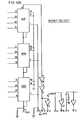
- the money select circuitry When registration signals are generated by the registration circuitry, they are applied to input terminals for money select circuitry as illustrated in Figures 6A and 6B. Connections to this circuitry in general depend upon the types of containers expected. For instance, in a market area wherein there are only 10 cent bottles and 20 cent bottles to be received, the money select circuitry may be connected to receive registration inputs only from terminals M-1 through M-4 as illustrated. Terminal M-1 might be connected to receive registration signals from registration circuitry which recognizes individual 10 cent bottles, while terminal M-2 might be connected to receive registration signals only from circuitry which recognizes pairs of 10 cent bottles arranged side by side in cartons. Similarly, input terminals M-3 and M-4 may receive registration signals for individual 20 cent bottles and 20 cent bottle pairs respectively.
Landscapes
- Physics & Mathematics (AREA)
- General Physics & Mathematics (AREA)
- Sorting Of Articles (AREA)
- Making Paper Articles (AREA)
- Supplying Of Containers To The Packaging Station (AREA)
- Auxiliary Devices For And Details Of Packaging Control (AREA)
Description
- This invention relates to systems for classifying empty beverage containers of a type known in the trade as returnable. These are containers, usually glass bottles, for which the beverage purchaser is charged a deposit fee at the time of purchase. When the purchaser returns the empty container to a designated redemption centre, the deposit fee is refunded. Most beverage sales outlets also operate redemption centres, and the operation of these centres is usually a troublesome matter which takes clerks away from other more profitable tasks.
- Beverages are commonly sold in containers of many different sizes, and in cartons containing groups of six or eight such containers. The customer may return the containers either individually or in cartons and may mix different types of containers in a single carton. It is the task of the redemption centre clerk to sort or classify the containers in accordance with their deposit values and to calculate the refund which is due. The clerk may make an actual refund or may give the customer a refund slip which can be redeemed at another location. This operation is so unprofitable that many supermarkets simply operate on an honour system, whereby customers stack their empties at a receiving location and report the return to a checkout clerk, who makes the appropriate refund.
- An article inspection system is described in U.S. Patent No. 3,837,486 (Gardner) which is concerned with a simplified apparatus capable of checking articles for proper shape or silhouette as these articles are continuously moved by a conveyor through an inspection station.
- In carrying out the Gardner invention, a pulse generating means is adapted to produce a train of pulses proportional in frequency to the speed of the conveyor and hence to the speed of the articles moving through the inspection station. Transducer means is mounted adjacent the conveyor and generates a "diameter" pulse having a duration proportional to the width or diameter of the article being inspected. Counter means is provided for recording the number of pulses produced during the duration of said "diameter" pulse, and means is provided in association with the counter to produce discrete "yes" and "no" output pulses when the count provided in the counter is above predetermined minimum and maximum values. Reject means is operable in response to these "yes" and "no" output signals for removing a defective article from the conveyor at a reject station, which station may be provided at the inspection station or downstream thereof.
- However, the Gardner invention is not suitable for a bottle identification system which has to be capable of recognizing a wide range of bottle types exhibiting unpredictable variations in light transmissivity.
- An alternative to the above described redemption techniques is an automatic system such as a system of the type described in Planke U.S. Patent 3,955,179. This system has a pair of conveyors, one for individual empty bottles and one for cartons. In operation the customer places the returned bottles and cartons on the appropriate conveyor for transportation through an illumination station. At the illumination station the containers are illuminated by a beam of collimated light, and a shadow of the containers is projected against an array of photo-detectors. The containers are identified by their shadows. This identification results in control signals for a logic network which computes the amount of the refund and controls the printing of a refund slip by an associated printer.
- The invention provides apparatus for classifying empty beverage containers (23) comprising conveyor means (10), for accepting said containers and carrying them to a storage area, alignment means (15) for aligning said containers in a single file along said conveyor means, illumination means (16) positioned to direct illumination across said conveyor means in the path of containers being transported therealong, photosensing means (18) which generate sensing signals in response to the reception of illumination of the type generated by said illumination means and which are positioned alongside the said conveyor opposite said illumination means so that said sensing signals in response to the reception of illumination of the type generated by said illumination means and which are positioned alongside the said conveyor opposite said illumination means so that said sensing signals indicate the presence or absence of one of said containers on said conveyor means, a clock pulse generator (36) which generates clock pulses in synchronism with the movement of said conveyor means, and container identification means connected to receive said sensing signal and said clock pulses and comprising a registration circuit (401, 402, 405, 407, 409, 411, 413) which identifies said containers (23) in response to said sensing signal and said clock pulses, characterized in that said registration circuit comprises means (401) for receiving said sensing signals and generating a count enabling signal in response to light-to-dark transitions of said sensing signals, counting means (402, 403, 407) which are connected to commence counting said clock pulses when said count enabling signal is generated and thereafter to generate a recognition enabling count and a recognition disabling count, and registration means (409, 411, 413) which generate a registration signal if and only if a dark-to-light transition of said sensing signals occurs after said recognition enabling count is reached and before said recognition disabling count is reached.
- One way of carrying out the invention is described in detail below with reference to the drawings which illustrate only one specific embodiment, in which:-
- Figure 1 is a schematic drawing of the mechanism of this invention.
- Figure 2 is a plan view of container handling mechanism in accordance with this invention,
- Figure 3 is a schematic illustration of container movement during recognition by a row of photocells and associated circuitry,
- Figures 4A and 4B is a schematic drawing of registration circuitry,
- Figures 5A and 5B are deleted.
- Figures 6A and 6B are a schematic drawing of money select circuitry.
- Figures 7A and 7B are a schematic drawing of calculation circuitry.
- A
conveyor arrangement 10 featured in this invention may be constructed as schematically illustrated in Figure 1. The arrangement includes aconveyor belt 11, with associated driving elements, an aligning mechanism as indicated generally at 15, and a paddle arrangement as indicated generally at 12. The cooperating operation ofconveyor belt 11,paddle arrangement 12, andaligning mechanism 15 can best be understood by reference to Figure 2. - Movement of
belt 11 is initiated by pushing a start button on a control panel (not illustrated). A customer who wishes to obtain a refund for empty beverage containers pushes the start button and thereafter loads individualempty containers 23 and cartons ofempty containers 24 uponbelt 11. Loading is performed at a receiving station, which is separated from the major portions of theconveyor 10 by awall 25. - After being loaded upon
belt 11,individual containers 23 andcartons 24 are met by afriction surface 26 onarm 27 ofaligning mechanism 15. A ratchet arrangement causesarm 27 to oscillate back and forth as illustrated generally by thearrow 28, and this urges the containers and cartons sidewardly againstsideboard 14.Sideboard 14 has a friction surface, which retards forward movement of the containers and cartons. The containers and cartons are trapped againstsideboard 14 and behindarm 27 until released by outward movement of the arm. Ablade 29 is pivotally attached toarm 27 and is urged against the cartons and containers by aspring mechanism 30. This produces separation between the cartons and containers in the direction of belt movement. - After movement past aligning
mechanism 15, the containers and cartons pass a series of microswitches (not illustrated), which are positioned so as to be actuated only by cartons. Thereafter the containers and cartons pass into an illumination region between anilluminating apparatus 16 and a series ofphotosensors 18.Illuminating apparatus 16 generates a series ofilluminating beams 17, which are directed angularly with respect to the direction transverse to the direction of conveyor movement. The angle between the beam direction and the transverse direction is preferably in the order of about 18 degrees, so that the identification circuits can recognize pairs of containers within a carton. Eachbeam 17 is directed toward an individual photocell 31 (Figure 3), and the beams are preferably beams of collimated infrared light produced by TIL 31 infrared light sources and collimating lenses. Preferably eachbeam 17 has a diameter in the order of about 0.635 cm. - After passage through the illuminating station the containers and cartons pass under
paddle arrangement 12.Paddle arrangement 12 includes a series ofpaddles 13, which may be actuated to move in the direction indicated by thearrow 21.Paddle arrangement 12 is actuated whenever acarton 24 is positioned thereunder. As mentioned previously, the system is conditioned by a series of switches to discriminate between cartons and individual containers. Thuspaddle arrangement 12 is never actuated during passage of an individual container thereunder, so that individual containers are carried along to a bottle storage area. - When
paddle arrangement 12 is actuated, apaddle 13 is brought into contact with the side of a carton, and the carton is pushed transversely onto a separating station 19.Paddles 13 swing freely in ferris wheel fashion onchains 51, but during the lower quadrant of their movement, they are held rigidly downward byarms 52 which include aroller 53 for bearing against atrack 54. This enables the paddles to push sidewardly against cartons. - Separating station 19 comprises a series of
rollers 20, which are driven either forwardly or reversely by adrive motor 22. If the system recognizes the carton as being properly loaded, then drivemotor 22 drives rollers forwardly, and the carton is accepted. If the carton is improperly loaded with bottles of different size or has empty cells, thenmotor 22 drivesrollers 22 reversely, and the carton is rejected. - The technique for identifying a container for refund purposes can be understood by reference to Figure 3. As the
belt 33 carries acontainer 23 in front ofphotosensor array 18, the light falling upon the vertically arranged row ofphotocells 31 is periodically blocked. Eachphotocell 31 has anoutput line 32, which transmits an electrical signal corresponding to light and dark conditions at the photocell. By way of example, the illustratedphotocell 31 a may be the first photocell to sense the presence of thecontainer 23. This causes a transition in the output signal fromline 32a as indicated at 33. Asecond photocell 31 b has a light to dark transition somewhat later in time, followed at a still later time by a dark to light transition, both transitions being indicated by the output signal online 32b. The latter transition on the output signal fromline 32b is indicated by thereference numeral 34.Lines 32 are connected through a series of gates to different ones of a plurality of registration circuits. For processing the container illustrated in Figure 3, one such registration circuit is connected tolines transition 34 occurs after time t1 and before time t2. The time period between t1 and t2 is established by counting a series ofclock pulses 35 generated by anencoder 36 arranged for viewing anoptical disc 37 mounted on thedrive motor 38. Output pulses fromencoder 36 are carried byline 39. - It will be seen that
clock pulses 35 occur in synchronism with the actual physical movement ofcontainer 23. In a typical case such an encoding arrangement may generate anew clock pulse 35 eachtime container 23 moves a distance of 0.0254 cm. Thus by counting theclock pulses 35 the registration circuitry responds to beverage containers having a particular horizontal dimension within some predetermined dimensional range. For instance, a particular registration circuit may be configured for recognizing bottles having an illustrated dimension X equal to 6.35 cm. A bottle meeting this criterion would cause thetransition 34 to occur online 32b at a point in time determined by counting 250 of theclock pulses 35. In order to allow for some error a registration "window" of perhaps 20 clock pulses might be employed. This would cause generation of a registration signal for bottles having a dimension X ranging between 6.096 cm and 6.604 cm. It is apparent that a system constructed in accordance with this invention could be made to recognize a great many different registration conditions. - Electrical circuitry for controlling the apparatus of Figures 1 and 2 and generating container value signals is illustrated in Figures 4A, 4B, 6A, 6B, 7A and 7B. In addition to the illustrated circuitry the apparatus utilizes fairly conventional power supplies, display controls, transmission lines, clock signal generators, photosensors, drivers, and amplifiers. Table 1 lists circuit types for integrated circuits illustrated in the detailed electrical schematics presented herein.


- Figures 4A and 4B illustrate the registration circuitry, which generates the above mentioned registration pulses. The circuitry of Figures 4A and 4B generates a registration signal for a container having particular dimension within some predetermined range or for different containers having the specified dimension within that range. Typically empty containers can be grouped in groups having some common dimensional characteristic within a relatively small dimensional range and a common refund value. The circuitry of Figures 4A and 4B would generate a registration signal for all such containers, and this registration signal would appear at
output terminals integrated circuit 413. Containers having a different common dimensional characteristic are identified by registration circuitry similar to the circuitry of Figures 4A and 4B but programmed in a different manner as hereinafter described. -
Conveyor clock pulses 35 are received at terminal J of the registration circuitry and are applied to the clock terminals ofcounters transition 33 appearing online 32a as described above with reference to Figure 3. The signal level at terminal C also controls conveyor clock counting. Terminal C is connected to that one ofphotocells 31 which is located at a height immediately over the top of the container. The photocell which is connected to terminal C must be illuminated to order for counting to be enabled. - It will be seen that
counter 402 is connected to acounter 405 in serial fashion, so that an output appears atterminal 10 ofcounter 405 after a predetermined number of conveyor clock pulses have been counted. This count, which takes place during a time period t1 as illustrated in Figure 3, is controlled by presetting the counting control terminals ofcounters - While
clock 407 is counting,input terminal 5 of flip-flop 411 is H1, so that the flip-flop is conditioned to respond to a signal transition, such as thetransition 34, appearing on input terminal H. If the signal transition occurs at terminal H during the registration window, then flip-flop 411 is triggered to produce an output for application togate portion 416 ofintegrated circuit 413.Integrated circuit 413 produces registration output signals on its N and P terminals. - Six
terminals 421 through 426 are provided for added counting flexibility. For a simple registration, as above described, a jumper is attached betweenterminals terminals counters flops terminals terminals terminals terminals - When registration signals are generated by the registration circuitry, they are applied to input terminals for money select circuitry as illustrated in Figures 6A and 6B. Connections to this circuitry in general depend upon the types of containers expected. For instance, in a market area wherein there are only 10 cent bottles and 20 cent bottles to be received, the money select circuitry may be connected to receive registration inputs only from terminals M-1 through M-4 as illustrated. Terminal M-1 might be connected to receive registration signals from registration circuitry which recognizes individual 10 cent bottles, while terminal M-2 might be connected to receive registration signals only from circuitry which recognizes pairs of 10 cent bottles arranged side by side in cartons. Similarly, input terminals M-3 and M-4 may receive registration signals for individual 20 cent bottles and 20 cent bottle pairs respectively.
- If 10 cent bottles are returned in a six bottle carton, three registration signals will appear at terminal M-2, and three 20 cent counts will be made by the system. If a single 10 cent bottle is registered, then a single 20 cent count is made. The calculation circuitry of Figures 7A and 7B perform a division by 2 in order to reduce such a single 20 cent count to a 10 cent output. 20 cent bottles are handled in a similar manner.
- For the above example money counts are added by
integrated circuits chain comprising counters integrated circuits line 611, which is generated by the calculation circuitry of Figures 7A and 7B and appears as an output atline 715 thereof. The money select circuitry counts 100 KHz clock pulses appearing atline 610, and when the countdown is completed a DONE signal appears atline 612.
Claims (10)
Priority Applications (1)
| Application Number | Priority Date | Filing Date | Title |
|---|---|---|---|
| AT79301419T ATE3914T1 (en) | 1978-07-17 | 1979-07-17 | DEVICE AND METHOD FOR THE CLASSIFICATION OF EMPTY BEVERAGE CONTAINERS. |
Applications Claiming Priority (4)
| Application Number | Priority Date | Filing Date | Title |
|---|---|---|---|
| US92485478A | 1978-07-17 | 1978-07-17 | |
| US924854 | 1978-07-17 | ||
| US05/924,855 US4276467A (en) | 1978-07-17 | 1978-07-17 | Apparatus for receiving empty beverage containers |
| US924855 | 1978-07-17 |
Publications (3)
| Publication Number | Publication Date |
|---|---|
| EP0007248A2 EP0007248A2 (en) | 1980-01-23 |
| EP0007248A3 EP0007248A3 (en) | 1980-02-06 |
| EP0007248B1 true EP0007248B1 (en) | 1983-06-22 |
Family
ID=27129896
Family Applications (1)
| Application Number | Title | Priority Date | Filing Date |
|---|---|---|---|
| EP79301419A Expired EP0007248B1 (en) | 1978-07-17 | 1979-07-17 | Apparatus and method for classifying empty beverage containers |
Country Status (4)
| Country | Link |
|---|---|
| EP (1) | EP0007248B1 (en) |
| DE (1) | DE2965726D1 (en) |
| ES (2) | ES482532A1 (en) |
| NO (1) | NO792325L (en) |
Families Citing this family (8)
| Publication number | Priority date | Publication date | Assignee | Title |
|---|---|---|---|---|
| US4259571A (en) * | 1979-05-25 | 1981-03-31 | The Mead Corporation | Apparatus and method for container recognition |
| SE446509B (en) * | 1985-05-14 | 1986-09-22 | Regionala Stiftelsen I Vermlan | DEVICE FOR SORTING FOOD DINING |
| FR2620053B1 (en) * | 1987-09-04 | 1990-09-07 | Maintenance Manutention Sarl | SORTING DEVICE FOR BOOKS AND SMALL OBJECTS |
| FR2620054B1 (en) * | 1987-09-07 | 1990-02-16 | Maintenance Manutention Sarl | MEDIUM PARCEL SORTING DEVICE "POSTAL PACKAGE TYPE" |
| US5314072A (en) * | 1992-09-02 | 1994-05-24 | Rutgers, The State University | Sorting plastic bottles for recycling |
| WO2013123228A1 (en) * | 2012-02-14 | 2013-08-22 | Miyashiro Thomas H | Apparatus for counting deposit beverage containers |
| US12475339B2 (en) | 2020-05-25 | 2025-11-18 | Trackonomy Systems, Inc. | System and method for enhanced asset tracking and security for border protection and other applications |
| US11954639B2 (en) * | 2021-01-25 | 2024-04-09 | Trackonomy Systems, Inc. | Method for detecting and tracking groups of assets and system thereof |
Family Cites Families (6)
| Publication number | Priority date | Publication date | Assignee | Title |
|---|---|---|---|---|
| US3343638A (en) * | 1961-05-31 | 1967-09-26 | Taylor Mfg | Article receiving and storage apparatus |
| US3549890A (en) * | 1969-01-16 | 1970-12-22 | Emhart Corp | Article inspection apparatus |
| US3955179A (en) * | 1971-12-14 | 1976-05-04 | Tore Planke | Apparatus for automatic pattern recognition and registration of empty bottles |
| US3837486A (en) * | 1973-07-09 | 1974-09-24 | Emhart Corp | Article inspection system |
| SE7511591L (en) * | 1975-10-16 | 1977-04-17 | Ab Platmanufaktur | RECEIVER FOR ARTICLES LOCATED IN THE STORAGE BODY |
| US4120403A (en) * | 1976-06-28 | 1978-10-17 | George E. Lauer | Photoelectric apparatus for sorting variegated articles according to size |
-
1979
- 1979-07-12 NO NO792325A patent/NO792325L/en unknown
- 1979-07-17 EP EP79301419A patent/EP0007248B1/en not_active Expired
- 1979-07-17 DE DE7979301419T patent/DE2965726D1/en not_active Expired
- 1979-07-17 ES ES482532A patent/ES482532A1/en not_active Expired
- 1979-11-22 ES ES486243A patent/ES486243A1/en not_active Expired
Also Published As
| Publication number | Publication date |
|---|---|
| EP0007248A3 (en) | 1980-02-06 |
| ES486243A1 (en) | 1980-05-16 |
| EP0007248A2 (en) | 1980-01-23 |
| NO792325L (en) | 1980-01-18 |
| ES482532A1 (en) | 1980-02-16 |
| DE2965726D1 (en) | 1983-07-28 |
Similar Documents
| Publication | Publication Date | Title |
|---|---|---|
| US4253573A (en) | Apparatus for handling empty beverage containers | |
| US3955179A (en) | Apparatus for automatic pattern recognition and registration of empty bottles | |
| AU2020256359B2 (en) | Material handling apparatus with delivery vehicles | |
| US4707251A (en) | Container scanning and accounting device | |
| US4717026A (en) | Container scanning and accounting device | |
| AU2017308144B2 (en) | Object sensing and handling system and associated methods | |
| US4558212A (en) | Container redemption method and apparatus | |
| US6540062B2 (en) | Method for controlling items belonging to a commissioning order and a device for carrying out said method | |
| WO1998002371A1 (en) | Device for a conveyor means | |
| EP0020108A1 (en) | Apparatus and method for container recognition | |
| EP0007248A2 (en) | Apparatus and method for classifying empty beverage containers | |
| EP0580815B1 (en) | Sortation system for cigarette packs | |
| US4276467A (en) | Apparatus for receiving empty beverage containers | |
| EP0036769A1 (en) | Checkout system | |
| CA1149333A (en) | Single and cartonned beverage container depository and refund determining system | |
| RU2743623C1 (en) | Sorting system and method for sorting items | |
| NZ744108B2 (en) | Material handling apparatus with delivery vehicles | |
| NZ769138B2 (en) | Material handling apparatus with delivery vehicles |
Legal Events
| Date | Code | Title | Description |
|---|---|---|---|
| PUAI | Public reference made under article 153(3) epc to a published international application that has entered the european phase |
Free format text: ORIGINAL CODE: 0009012 |
|
| PUAL | Search report despatched |
Free format text: ORIGINAL CODE: 0009013 |
|
| AK | Designated contracting states |
Designated state(s): AT BE CH DE FR GB IT LU NL SE |
|
| AK | Designated contracting states |
Designated state(s): AT BE CH DE FR GB IT LU NL SE |
|
| 17P | Request for examination filed | ||
| ITF | It: translation for a ep patent filed | ||
| GRAA | (expected) grant |
Free format text: ORIGINAL CODE: 0009210 |
|
| AK | Designated contracting states |
Designated state(s): AT BE CH DE FR GB IT LU NL SE |
|
| REF | Corresponds to: |
Ref document number: 3914 Country of ref document: AT Date of ref document: 19830715 Kind code of ref document: T |
|
| REF | Corresponds to: |
Ref document number: 2965726 Country of ref document: DE Date of ref document: 19830728 |
|
| ET | Fr: translation filed | ||
| PLBE | No opposition filed within time limit |
Free format text: ORIGINAL CODE: 0009261 |
|
| STAA | Information on the status of an ep patent application or granted ep patent |
Free format text: STATUS: NO OPPOSITION FILED WITHIN TIME LIMIT |
|
| PGFP | Annual fee paid to national office [announced via postgrant information from national office to epo] |
Ref country code: CH Payment date: 19840618 Year of fee payment: 6 |
|
| PGFP | Annual fee paid to national office [announced via postgrant information from national office to epo] |
Ref country code: DE Payment date: 19840622 Year of fee payment: 6 |
|
| 26N | No opposition filed | ||
| PGFP | Annual fee paid to national office [announced via postgrant information from national office to epo] |
Ref country code: SE Payment date: 19840630 Year of fee payment: 6 |
|
| PGFP | Annual fee paid to national office [announced via postgrant information from national office to epo] |
Ref country code: AT Payment date: 19850610 Year of fee payment: 7 |
|
| PG25 | Lapsed in a contracting state [announced via postgrant information from national office to epo] |
Ref country code: AT Effective date: 19860717 |
|
| PG25 | Lapsed in a contracting state [announced via postgrant information from national office to epo] |
Ref country code: SE Effective date: 19860718 |
|
| PG25 | Lapsed in a contracting state [announced via postgrant information from national office to epo] |
Ref country code: CH Effective date: 19860731 |
|
| REG | Reference to a national code |
Ref country code: CH Ref legal event code: PL |
|
| PG25 | Lapsed in a contracting state [announced via postgrant information from national office to epo] |
Ref country code: DE Effective date: 19870401 |
|
| GBPC | Gb: european patent ceased through non-payment of renewal fee | ||
| PG25 | Lapsed in a contracting state [announced via postgrant information from national office to epo] |
Ref country code: GB Effective date: 19881118 |
|
| EPTA | Lu: last paid annual fee | ||
| EUG | Se: european patent has lapsed |
Ref document number: 79301419.2 Effective date: 19870518 |
|
| PGFP | Annual fee paid to national office [announced via postgrant information from national office to epo] |
Ref country code: FR Payment date: 19980611 Year of fee payment: 20 |
|
| PGFP | Annual fee paid to national office [announced via postgrant information from national office to epo] |
Ref country code: NL Payment date: 19980629 Year of fee payment: 20 |
|
| PGFP | Annual fee paid to national office [announced via postgrant information from national office to epo] |
Ref country code: LU Payment date: 19980701 Year of fee payment: 20 |
|
| PGFP | Annual fee paid to national office [announced via postgrant information from national office to epo] |
Ref country code: BE Payment date: 19980713 Year of fee payment: 20 |
|
| BE20 | Be: patent expired |
Free format text: 19990717 THE *MEAD CORP. |
|
| PG25 | Lapsed in a contracting state [announced via postgrant information from national office to epo] |
Ref country code: NL Free format text: LAPSE BECAUSE OF EXPIRATION OF PROTECTION Effective date: 19990717 Ref country code: LU Free format text: LAPSE BECAUSE OF EXPIRATION OF PROTECTION Effective date: 19990717 |
|
| NLV7 | Nl: ceased due to reaching the maximum lifetime of a patent |
Effective date: 19990717 |