EP0007009A1 - Method for displaying the magnitude of remote control signals for a rotary press - Google Patents
Method for displaying the magnitude of remote control signals for a rotary press Download PDFInfo
- Publication number
- EP0007009A1 EP0007009A1 EP79101890A EP79101890A EP0007009A1 EP 0007009 A1 EP0007009 A1 EP 0007009A1 EP 79101890 A EP79101890 A EP 79101890A EP 79101890 A EP79101890 A EP 79101890A EP 0007009 A1 EP0007009 A1 EP 0007009A1
- Authority
- EP
- European Patent Office
- Prior art keywords
- display
- rough
- light
- actuators
- fine
- Prior art date
- Legal status (The legal status is an assumption and is not a legal conclusion. Google has not performed a legal analysis and makes no representation as to the accuracy of the status listed.)
- Granted
Links
Images


Classifications
-
- G—PHYSICS
- G01—MEASURING; TESTING
- G01R—MEASURING ELECTRIC VARIABLES; MEASURING MAGNETIC VARIABLES
- G01R13/00—Arrangements for displaying electric variables or waveforms
- G01R13/40—Arrangements for displaying electric variables or waveforms using modulation of a light beam otherwise than by mechanical displacement, e.g. by Kerr effect
- G01R13/404—Arrangements for displaying electric variables or waveforms using modulation of a light beam otherwise than by mechanical displacement, e.g. by Kerr effect for discontinuous display, i.e. display of discrete values
- G01R13/405—Arrangements for displaying electric variables or waveforms using modulation of a light beam otherwise than by mechanical displacement, e.g. by Kerr effect for discontinuous display, i.e. display of discrete values using a plurality of active, i.e. light emitting, e.g. electro-luminescent elements, i.e. bar graphs
- G01R13/406—Arrangements for displaying electric variables or waveforms using modulation of a light beam otherwise than by mechanical displacement, e.g. by Kerr effect for discontinuous display, i.e. display of discrete values using a plurality of active, i.e. light emitting, e.g. electro-luminescent elements, i.e. bar graphs representing measured value by a dot or a single line
-
- B—PERFORMING OPERATIONS; TRANSPORTING
- B41—PRINTING; LINING MACHINES; TYPEWRITERS; STAMPS
- B41F—PRINTING MACHINES OR PRESSES
- B41F31/00—Inking arrangements or devices
-
- B—PERFORMING OPERATIONS; TRANSPORTING
- B41—PRINTING; LINING MACHINES; TYPEWRITERS; STAMPS
- B41F—PRINTING MACHINES OR PRESSES
- B41F33/00—Indicating, counting, warning, control or safety devices
- B41F33/02—Arrangements of indicating devices, e.g. counters
Definitions
- the invention relates to a method for displaying manipulated variables of remote-controlled, zonal actuators for dosing the ink and / or moisture control at a central remote control station of a rotary printing press, the manipulated variables being converted into display signals and the display signals for representing the color and / or moisture profile by means of the individual Color and / or wet zones associated LEDs are made visible.
- the analog display of the color profile can in no way be dispensed with, since this continues to be valuable information for the operating personnel, even if it is also insufficient for setting the coloring of individual specific color zones, especially when the quality of the print product is subject to high quality requirements also makes a not negligible contribution.
- An increase in the number of individual zonal light-emitting diodes is obvious, but it cannot remedy the situation either, since e.g. B. even a doubling of the number of light-emitting diodes is not sufficient for the required display accuracy, especially since the space required for this is usually not available at the central remote control station.
- a multiplication of the accuracy of the existing analog display for reading decimals of the previous display values is therefore subject to spatial limits.
- the object of the invention is to provide, in addition to the already existing analog display of the color profile, a method for fine display, which is a further ge with little effort provides accurate residual information about the state of fine adjustment of the coloring of the individual color zones and displays this to the operating personnel precisely and easily understandable, so that the information about the coloring is complete.
- the object is achieved in that the same display signals are used for two separate displays, one of which is provided as an analog rough display of the color and / or moisture profile, which provides the basic value for the manipulated variables for the rough adjustment of the actuators and the other than digital fine display, which shows the intermediate value for the manipulated variables for fine adjustment of the actuators.
- the analog coarse display is carried out by means of vertical, zonal rows of light-emitting diodes and the digital fine display is by means of a digital signal transmitter which is additionally assigned to each row of light-emitting diodes.
- both displays both the rough analogue display and the digital fine display
- the fine display of the Coarse display is superimposed in the zonal rows of LEDs.
- This display method makes use of the existing LED display to display the color profile. Due to the simultaneous use of the rows of LEDs for both rough and fine display, an additional separate display along with the associated switching electronics is completely unnecessary. The result is considerable cost savings.
- the rough analogue display takes place by constantly lighting up and the digital fine display simultaneously by pulsing individual LEDs of the zonal rows of LEDs.
- the intermediate value of the display signal between the display threshold and the response threshold of the next higher light-emitting diode, which cannot yet be processed is fed to the digital fine display.
- An example of an apparatus for carrying out the method according to the invention is that for the rough analog display of the color and / or moisture profile as a basic value for the manipulated variables for the rough adjustment of the actuators, vertical rows of light-emitting diodes and as a digital fine display for signaling the intermediate values of the display signals that cannot yet be displayed analogously Fine adjustment of the actuators digital signal transmitters are provided.
- Such an arrangement not only enables the operating personnel to obtain a quick and comprehensive overview of the color profile actually present as analog information, but at the same time also provides digital information about the fine-tuning state of the individual zonal color and / or moisture control elements, as a result of which targeted interventions in the form of Fine corrections in the color and / or moisture control in order to achieve good print quality can be carried out within a very short time.
- the digital signal transmitters are designed as numerical displays assigned to each zonal row of light-emitting diodes and arranged above them.
- these numerical displays the intermediate values of the manipulated variable that have not yet been detected by the next higher light-emitting diode within two successive light-emitting diodes for the operating personnel in the form of, for. B. decimals can be made easily recognizable, which is advantageous for increased quality requirements for printing accuracy.
- the printer can get down to speed zest time provide a clear overview of the color and / or moisture profile and the necessary corrections to the color and / or moisture control elements clearly broken down into rough and detailed information.
- zonal light-emitting diode displays in the form of vertical light-emitting diode rows 2 are arranged in accordance with the number of individual color zones of an inking unit, which is not shown and described in more detail, each color zone having a large number of light-emitting diodes 3 corresponding to the desired display accuracy, with increasing order numbers 4 can be assigned.
- a vertical row of light-emitting diodes 2 consists of twenty individual light-emitting diodes 3 arranged one above the other.
- Operating elements in the form of keys 5 are arranged below the rows of light-emitting diodes, with which the control command for reducing or increasing the zonal color quantities can be triggered.
- these higher-level digital signal transmitters are provided in the form of numerical displays 6.
- numerical displays 6 other visual displays, such as. B. flash lamps or acoustic signal generators in the form of signal horns or tickers are provided.
- FIG. 1 shows a section of the control table 1 of the central remote control station for the color zone adjustment in part over a range of four color zones.
- the connection of the light points of all activated light-emitting diodes 3 marks the color profile 7 across the width of the control table 1 as a qualitative rough statement about the actual existing color scheme.
- the color profile 7 is marked from left to right by the eighth, eleventh, tenth and sixth LEDs 3. The color profile in the section shown is thus sufficiently determined.
- the manipulated variable to be measured is by means of an encoder 8, z. B. a commonly used potentiometer, directly detected and supplied by this a downstream signal converter 9, in this case an analog-digital converter, as an analog input signal.
- the Sig nalwandler 9 converts the analog value of the input signal into a corresponding digital value that can be used for display.
- a rough display and a fine display go off parallel to one another.
- the converted display signal is fed to the rough display alone or additionally to the fine display, both of which have a different degree of resolution.
- this display signal becomes visible in the rough display by activating a light-emitting diode 3.
- the simultaneous lighting up of one light emitting diode of 3 different zones results in an analog representation for the color profile.
- this signal provides rough information.
- the activated light-emitting diode 3 does not provide any information about the intermediate values of the signal within the response thresholds of a light-emitting diode 3.
- the additional fine display is used to display these intermediate values in addition to the rough information.
- the value of the display signal which exceeds the lower response threshold of a light-emitting diode 3 is fed to the numerical display 6 and brought to fine display in digital digits.
- the degree of resolution of this digital fine display is considerably greater than that of the rough analog display for the color profile.
- the LED 3 remains activated in accordance with the retracted position of the actuator; the associated numerical display lights up. So z. B. the numerical display in the third numerical display 6 from the left that the actuator for the assigned color zone at deci painterly division by the value 0.2 beyond the numerical value assigned to the tenth light-emitting diode 3 is also open for coloring.
- the number zero in the first numerical display 6 means that the signal value for the lower response threshold of the sixth LED 3 is present here.
- the numerical display As a rule, a single decimal place on the numerical display is sufficient. The accuracy achieved with this corresponds at most to color quality requirements for the printed product.
- another digital, optically operating signal transmitter 6 can also be provided, the number of the transmitted pulses, e.g. B. flashes of light, a measure of the intermediate value of the display signal not yet detected by the light emitting diode 3.
- a simplification for carrying out the display method results in a particularly advantageous manner in that the light-emitting diodes 3 which are already available for the rough display of the color profile 7 are simultaneously used for the fine display, so that an additional display is completely unnecessary.
- sixteen individual light-emitting diodes 3 arranged one above the other are combined to form a vertical row of light-emitting diodes 2.
- the display is carried out in such a way that the light-emitting diode 3 activated for the analog rough display of the color profile 7 glows continuously with the same intensity, while a further light-emitting diode 3 of the same light-emitting diode row 2 with a different order number 4 by flashing in a pulsed manner or by weaker glowing, d.
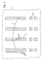
- a second exemplary embodiment of the display device shown in FIG. 4 shows the same structure as that described in FIG. 3, the rough analog display of the color profile 7 likewise taking place in the same way.
- the main difference of this second exemplary embodiment from the first is that the degree of resolution of the digital fine display has been doubled by the possibility of activating either one or two successive light-emitting diodes 3 of a row of light-emitting diodes 2.
- the simultaneous flashing of two successive light-emitting diodes 3 additionally signals an intermediate value lying in the middle between the two flashing light-emitting diodes 3.
- a constant lighting up of the eleventh LED 3 and a simultaneous pulse-like flashing of the seventh and eighth LED 3 in the second row of LEDs 2 from the left of FIG. 4 means that the actuator assigned to this color zone by the value 15/32 of the range from LED 3 to LED 3 is open beyond the lower response value of the eighth LED 3.
- a display with such a high degree of resolution also meets the highest quality requirements for the color quality of the printed product.
Abstract
Die Erfindung betrifft ein Verfahren zum Anzeigen von Stellgrössen fernbedienter, zonaler Stellgliederzum Dosieren der Farb- und oder Feuchtführung an einem zentralen Fernsteuerplatz einer Rotationsdruckmaschine. Die Steligrossen werden in Anzeigesignale umgewandelt und diese jeweils zwei voneinander unabhängigen Anzeigen zugeführt, einer analogen Grobanzeige und einer digitalen Feinanzeige. In der analogen Grobanzeige wird das Farb- und/oder Feuchtprofil mittels einzelnen Farb- und/oder Feuchtzonen zugeordneten Leuchtdiodenreihen (2) dargestellt. Die analoge Grobanzeige liefert ausschliesslich die Grundwerte für die Stellgrossen zur Grobeinstellung der Stellglieder. Die digitale Feinanzeige weist eine weitaus grossere Auflösung auf als die analoge Grobanzeige und liefert zusatzlich zu dieser die analog noch nicht anzeigbaren Zwischenwerte für die Stellgrossen zur Feineinstellung der Stellglieder. Die digitale Feinanzeige ist der analogen Grobanzeige vorzugsweise überlagert, wobei die analogue Grobanzeige durch konstantes Aufleuchten und die digitale Feinanzeige durch gleichzeitiges, impulsartiges Blinken einzelner Leuchtdioden ein und derselben Leuchtdiodenreihen signalisiert wird.The invention relates to a method for displaying manipulated variables of remote-controlled, zonal actuators for metering the ink and / or damp guidance at a central remote control station of a rotary printing press. The final values are converted into display signals and these are each fed to two independent displays, an analog rough display and a digital fine display. In the rough analog display, the color and / or moisture profile is shown by means of light-emitting diode rows (2) assigned to individual color and / or wet zones. The rough analog display only provides the basic values for the actuating variables for the rough adjustment of the actuators. The digital fine display has a much greater resolution than the rough analog display and, in addition to this, supplies the intermediate values for the actuating variables for fine adjustment of the actuators, which cannot yet be displayed analogously. The digital fine display is preferably superimposed on the analog rough display, the analogue rough display being signaled by constant lighting and the digital fine display by simultaneous, pulse-like flashing of individual LEDs of one and the same row of LEDs.
Description
Die Erfindung betrifft ein Verfahren zum Anzeigen von Stellgrößen fernbedienter, zonaler Stellglieder zum Dosieren der Farb- und/oder Feuchtführung an einem zentralen Fernsteuerplatz einer Rotationsdruckmaschine, wobei die Stellgrößen in Anzeigesignale umgewandelt und die Anzeigesignale zur Darstellung des Farb- und/oder Feuchteprofils mittels den einzelnen Farb- und/oder Feuchtzonen zugeordneten Leuchtdioden sichtbar gemacht werden.The invention relates to a method for displaying manipulated variables of remote-controlled, zonal actuators for dosing the ink and / or moisture control at a central remote control station of a rotary printing press, the manipulated variables being converted into display signals and the display signals for representing the color and / or moisture profile by means of the individual Color and / or wet zones associated LEDs are made visible.
Es ist bekannt, im Zuge der weiter fortschreitenden Automatisierungsmaßnahmen an Druckmaschinen der Firma Heidelberger Druckmaschinen AG zur Entlastung des Bedienungspersonals sowie zur Verkürzung der Einrichtezeiten die Farbzonenverstellung zum Verändern der Farbzufuhr mittels den einzelnen Farbzonen eines Farbwerkes zugeordneten Stellgliedern vorzunehmen.It is known, in the course of the progressive automation measures on printing presses from Heidelberger Druckmaschinen AG to relieve the operating personnel and to shorten the set-up times, to carry out the ink zone adjustment to change the ink supply by means of actuators assigned to the individual ink zones of an inking unit.
Wie in den "Heidelberger Nachrichten" 3/35, Jahrgang 1977 und in einer anläßlich der "DRUPA" 1977 herausgegebenen Broschüre "Heidelberg Offset CPC" beschrieben, erweist es sich für die Steuerung derartiger Stellglieder als vorteilhaft, das sogenannte Farbprofil am zentralen Fernsteuerplatz der Druckmaschine in Form einer Analoganzeige anzudeuten. Die der jeweiligen Farbschichtdicke der betreffenden Farbzonen entsprechende Lage einzelner aktivierter Leuchtdioden, bezogen auf eine Nullinie, markiert dabei über die Breite des Fernsteuerplatzes hinweg das sogenannte Farbprofil, das dem Bedienungspersonal eine qualitativ wertvolle Aussage über den momentanen Stand der Farbgebung liefert.As described in the "Heidelberger Nachrichten" 3/35, born in 1977 and in a brochure "Heidelberg Offset CPC" published on the occasion of "DRUPA" 1977, it has proven to be advantageous for the control of such actuators, the so-called color profile at the central remote control station of the printing press in the form of an analog display. The position of individual activated light-emitting diodes, based on a zero line, corresponding to the respective color layer thickness of the respective color zones, marks the so-called color profile across the width of the remote control station, which provides the operating personnel with qualitatively valuable information about the current status of the coloring.
In vielen Fällen, in denen nicht allzu hohe Anforderungen an die Qualität des Druckproduktes gestellt werden, reicht diese relativ genaue Aussage über die Farbgebung aus, insbesondere dann, wenn ohnehin mit einer eingeschränkten Genauigkeit der Rückmeldung der Farbschichtdicke, z. B. infolge eines geringen Auflösungsgrades der Stellgrößen für das Farbprofil gerechnet werden muß, zumal die Erfassung der Stellgröße, wie z. B. die Stellung einer Farbzonenschraube oder die Lage eines bestimmten Punktes am Farbmesser zu einer ortsfesten Koordinate,nicht die tatsächlich vorhandene Farbschichtdicke darstellt.In many cases, in which not too high demands are made on the quality of the printed product, this relatively precise statement about the coloring is sufficient, especially when the accuracy of the feedback of the ink layer thickness, for. B. due to a low degree of resolution of the position sizes for the color profile must be expected, especially since the acquisition of the manipulated variable, such as. B. the position of an ink fountain key or the position of a certain point on the color knife to a fixed coordinate, does not represent the actual thickness of the ink layer.
Die Entwicklung fortschrittlicher, die wirkliche Farbschichtdicke repräsentierender Stellglieder, wie z. B. in der Fernsteuereinrichtung "Heidelberg Offset CPC" realisiert, hat zur Folge, daß die obengenannte Auswertungsmethode zur Erkennung des genauen Farbprofils über die Maschinenbreite nicht mehr ausreicht. Die bessere Reproduzierbarkeit und der mittlerweile erzielbare größere Auflösungsgrad der Stellgrößen für das Farbprofil ermöglichen es, für hinreichende Genauigkeit in der Anzeige zu sorgen, um die Vorteile dieser neuen Steuersysteme optimaler ausnutzen zu können.The development of advanced actuators representing the real ink layer thickness, such as B. realized in the remote control device "Heidelberg Offset CPC", has the consequence that the above-mentioned evaluation method for recognizing the exact color profile across the machine width is no longer sufficient. The better reproducibility and the now achievable higher degree of resolution of the manipulated variables for the color profile make it possible to ensure sufficient accuracy in the display in order to be able to make optimal use of the advantages of these new control systems.
Auf die Analoganzeige des Farbprofils kann aber keinesfalls verzichtet werden, da diese für das Bedienungspersonal nach wie vor eine wertvolle Information darstellt, wenngleich sie auch für die Einstellung der Farbgebung einzelner bestimmter Farbzonen, insbesondere bei hohen Güteanforderungen an die Farbqualität des Druckproduktes, einen ungenügenden, wenn auch nicht zu vernachlässigenden Beitrag liefert. Eine Erhöhung der Anzahl der einzelnen zonalen Leuchtdioden ist naheliegend, kann jedoch auch keine Abhilfe schaffen, da z. B. selbst eine Verdoppelung der Anzahl der Leuchtdioden nicht für die geforderte Anzeigengenauigkeit ausreicht, zumal der dazu benötigte Platzbedarf am zentralen Fernsteuerplatz meistens nicht vorhanden ist. Einer Vervielfachung der Genauigkeit der vorhandenen Analoganzeige zum Ablesen von Dezimalen der bisherigen Anzeigewerte sind somit räumlich Grenzen gesetzt.However, the analog display of the color profile can in no way be dispensed with, since this continues to be valuable information for the operating personnel, even if it is also insufficient for setting the coloring of individual specific color zones, especially when the quality of the print product is subject to high quality requirements also makes a not negligible contribution. An increase in the number of individual zonal light-emitting diodes is obvious, but it cannot remedy the situation either, since e.g. B. even a doubling of the number of light-emitting diodes is not sufficient for the required display accuracy, especially since the space required for this is usually not available at the central remote control station. A multiplication of the accuracy of the existing analog display for reading decimals of the previous display values is therefore subject to spatial limits.
Demgemäß besteht die Aufgabe der Erfindung darin, zusätzlich zu der bereits vorhandenen Analoganzeige des Farbprofils ein Verfahren zur Feinanzeige zu schaffen, das mit geringem Aufwand eine weitere genaue Restinformation über den Feineinstell- Zustand der Farbgebung der einzelnen Farbzonen liefert und diese dem Bedienungspersonal präzise und leicht erfaßbar anzeigt, so daß die Information über die Farbgebung komplett ist.Accordingly, the object of the invention is to provide, in addition to the already existing analog display of the color profile, a method for fine display, which is a further ge with little effort provides accurate residual information about the state of fine adjustment of the coloring of the individual color zones and displays this to the operating personnel precisely and easily understandable, so that the information about the coloring is complete.
Die derart gestellte Aufgabe wird erfindungsgemäß dadurch gelöst, daß dieselben Anzeigesignale verwendet werden für zwei voneinander getrennte Anzeigen, von denen die eine als analoge Grobanzeige des Farb- und/oder Feuchteprofils vorgesehen ist, die den Grundwert für die Stellgrößen zur Grobeinstellung der Stellglieder liefert und die andere als digitale Feinanzeige, die den Zwischenwert für die Stellgrößen zur Feineinstellung der Stellglieder aufzeigt.The object is achieved in that the same display signals are used for two separate displays, one of which is provided as an analog rough display of the color and / or moisture profile, which provides the basic value for the manipulated variables for the rough adjustment of the actuators and the other than digital fine display, which shows the intermediate value for the manipulated variables for fine adjustment of the actuators.
Mit dem Anzeigeverfahren nach der Erfindung läßt sich mit geringem technischen Aufwand nicht nur eine analoge Grundinformation über die Anzeige des Farb- und/oder Feuchteprofils erzielen, sondern gleichzeitig in digitaler Form auch die dem Auflösungsgrad und der Reproduzierfähigkeit der Stellglieder gerade noch zugängliche Restinformation für eine Feineinstellung der einzelnen Farb- und/oder Feuchtzonenglieder gewinnen.With the display method according to the invention, not only analog basic information about the display of the color and / or moisture profile can be achieved with little technical effort, but at the same time in digital form also the remaining information for fine adjustment, which is just accessible to the degree of resolution and the reproducibility of the actuators of the individual color and / or wet zone elements.
Um eine klare Trennung zwischen der Grob- und der Feinanzeige zwecks guter Übersichtlichkeit beim Ablesen zu erzielen, erfolgt in Weiterbildung des Erfindungsgedankens die analoge Grobanzeige mittels vertikaler, zonaler Leuchtdiodenreihen und die digitale Feinanzeige mittels eines, einer jeden Leuchtdiodenreihe zusätzlich zugeordneten digitalen Signalgebers.In order to achieve a clear separation between the coarse and the fine display for the sake of good clarity when reading, in a further development of the inventive idea, the analog coarse display is carried out by means of vertical, zonal rows of light-emitting diodes and the digital fine display is by means of a digital signal transmitter which is additionally assigned to each row of light-emitting diodes.
Eine Möglichkeit zur vorteilhaften Durchführung des erfindungsgemäßen Verfahrens besteht darin, daß beide Anzeigen, sowohl die analoge Grobanzeige als auch die digitale Feinanzeige mittels der zonalen Leuchtdioden vorgenommen werden, wobei die Feinanzeige der Grobanzeige in den zonalen Leuchtdiodenreihen überlagert ist. Dieses Anzeigeverfahren macht sich die bereits vorhandene Leuchtdiodenanzeige zur Darstellung des Farbprofils zunutze. Durch die gleichzeitige Verwendung der Leuchtdiodenreihen sowohl zur Grob- als auch zur Feinanzeige erübrigt sich eine zusätzliche separate Anzeige nebst zugehöriger Schaltelektronik gänzlich. Eine erhebliche Kostenersparnis ist die Folge.One possibility for the advantageous implementation of the method according to the invention is that both displays, both the rough analogue display and the digital fine display, are carried out by means of the zonal light-emitting diodes, the fine display of the Coarse display is superimposed in the zonal rows of LEDs. This display method makes use of the existing LED display to display the color profile. Due to the simultaneous use of the rows of LEDs for both rough and fine display, an additional separate display along with the associated switching electronics is completely unnecessary. The result is considerable cost savings.
Um bei Überlagerung die beiden Anzeigen leicht voneinander unterscheiden zu können, erfolgt die analoge Grobanzeige durch konstantes Aufleuchten und die digitale Feinanzeige gleichzeitig durch impulsartiges Blinken einzelner Leuchtdioden der zonalen Leuchtdiodenreihen.In order to be able to easily distinguish the two displays from one another when superimposed, the rough analogue display takes place by constantly lighting up and the digital fine display simultaneously by pulsing individual LEDs of the zonal rows of LEDs.
In weiterer Ausgestaltung des erfindungsgemäßen Verfahrens wird bei Überschreiten eines der Anzeigesignale über die Ansprechschwelle einer Leuchtdiode einer der zonalen Leuchtdiodenreihen hinaus der zwischen dieser und-der Ansprechschwelle der nächst höheren Leuchtdiode liegende, analog noch nicht verarbeitungsfähige Zwischenwert des Anzeigesignals der digitalen Feinanzeige zugeführt. Durch eine z. B. dezimale Feinaufteilung des Abstandes zweier jeweils übereinanderliegender Leuchtdioden mit, aufeinanderfolgenden Ordnungsnummern wird eine hohe Anzeigegenauigkeit der Stellgrößen und dadurch große Einstellgenauigkeit der zonalen Stellglieder erzielt.In a further embodiment of the method according to the invention, if one of the display signals is exceeded beyond the response threshold of a light-emitting diode, one of the zonal light-emitting diode rows, the intermediate value of the display signal between the display threshold and the response threshold of the next higher light-emitting diode, which cannot yet be processed, is fed to the digital fine display. By a z. B. decimal fine division of the distance between two superimposed LEDs with consecutive order numbers, a high display accuracy of the manipulated variables and thereby great adjustment accuracy of the zonal actuators is achieved.
Eine beispielsweise Vorrichtung zur Durchführung des Verfahrens nach der Erfindung besteht darin, daß zur analogen Grobanzeige des Farb- und/oder Feuchteprofils als Grundwert für die Stellgrößen zur Grobeinstellung der Stellglieder vertikale Leuchtdiodenreihen und als digitale Feinanzeige zur Signalisierung der analog noch nicht anzeigbaren Zwischenwerte der Anzeigesignale zur Feineinstellung der Stellglieder digitale Signalgeber vorgesehen sind.An example of an apparatus for carrying out the method according to the invention is that for the rough analog display of the color and / or moisture profile as a basic value for the manipulated variables for the rough adjustment of the actuators, vertical rows of light-emitting diodes and as a digital fine display for signaling the intermediate values of the display signals that cannot yet be displayed analogously Fine adjustment of the actuators digital signal transmitters are provided.
Eine derartige Anordnung ermöglicht dem Bedienungspersonal nicht nur einen schnellen und umfassenden Überblick über das tatsächlich vorhandene Farbprofil als analoge Information, sondern liefert gleichzeitig auch eine digitale Information über den Feineinstell-Zustand der einzelnen zonalen Farb- und/oder Feuchtestellglieder, wodurch gezielte Eingriffe in Form von Feinkorrekturen in der Farb- und/oder Feuchtführung zwecks Erzielen einer guten Druckqualität innerhalb kürzester Zeit vorgenommen werden können.Such an arrangement not only enables the operating personnel to obtain a quick and comprehensive overview of the color profile actually present as analog information, but at the same time also provides digital information about the fine-tuning state of the individual zonal color and / or moisture control elements, as a result of which targeted interventions in the form of Fine corrections in the color and / or moisture control in order to achieve good print quality can be carried out within a very short time.
In Weiterbildung des Erfindungsgedankens sind die digitalen Signalgeber als einer jeden zonalen Leuchtdiodenreihe zugeordnete, oberhalb derselben angeordnete numerische Displays ausgebildet. In diesen numerischen Displays können die von der nächst höher liegenden Leuchtdiode noch nicht erfaßten Zwischenwerte der Stellgröße innerhalb zweier aufeinanderfolgender Leuchtdioden für das Bedienungspersonal in Form von z. B. Dezimalen leicht erkenntlich zugänglich gemacht werden, was für erhöhte Qualitätsanforderungen an die Druckgenauigkeit vorteilhaft ist.In a further development of the inventive concept, the digital signal transmitters are designed as numerical displays assigned to each zonal row of light-emitting diodes and arranged above them. In these numerical displays, the intermediate values of the manipulated variable that have not yet been detected by the next higher light-emitting diode within two successive light-emitting diodes for the operating personnel in the form of, for. B. decimals can be made easily recognizable, which is advantageous for increased quality requirements for printing accuracy.
Des weiteren besteht die Möglichkeit, daß sowohl für die analoge Grobanzeige des Farb- und/oder Feuchteprofils als Grundwert für die Stellgrößen zur Grobeinstellung der Stellglieder als auch für die digitale Feinanzeige zur Signalisierung der analog noch nicht anzeigbaren Zwischenwerte der Anzeigesignale zur Feineinstellung der Stellglieder dieselben vertikalen Leuchtdiodenreihen vorgesehen sind, wobei für die analoge Grobabzeige konstant aufleuchtende und für die dieser überlagerte digitale Feinanzeige impulsartig blinkende Leuchtdioden zur Anwendung kommen.Furthermore, there is the possibility that both for the analog rough display of the color and / or moisture profile as the basic value for the manipulated variables for the rough setting of the actuators and for the digital fine display for signaling the intermediate values of the display signals for the fine adjustment of the actuators, which cannot yet be displayed, for the same adjustment Rows of light-emitting diodes are provided, with light-emitting diodes being used for the rough analog display and for the digital fine display superimposed on them flashing in a pulsing manner.
Trotz der kostensparenden Zusammenlegung der beiden Anzeigen und Darstellung derselben unter Ausnutzung der gemeinsamen Leuchtdiodenreihen in einer Anzeigevorrichtung kann sich der Drucker in kürzester Zeit einen in Grob- und Feininformation klar aufgegliederten Überblick über das Farb- und/oder Feuchteprofil und die erforderlichen Stellkorrekturen der Farb- und/oder Feuchtestellglieder verschaffen.Despite the cost-saving combination of the two displays and the display of the same using the common rows of light emitting diodes in a display device, the printer can get down to speed zest time provide a clear overview of the color and / or moisture profile and the necessary corrections to the color and / or moisture control elements clearly broken down into rough and detailed information.
Weitere vorteilhafte Ausgestaltungen des Erfindungsgedankens sind in der nachfolgenden Beschreibung und in den Unteransprüchen 3, 4, 7, 9, 10 und 14 enthalten.Further advantageous refinements of the inventive concept are contained in the following description and in
Die Erfindung wird im folgenden in Form einer ausschnittsweise in den Zeichnungen dargestellten Grundausführung sowie anhand zweier Ausführungsbeispiele einer Anzeigevorrichtung für die Farbführung näher erläutert.The invention is explained in more detail below in the form of a basic version shown in detail in the drawings and using two exemplary embodiments of a display device for the color guide.
Es zeigt:
- Fig. 1 Eine ausschnittsweise Darstellung einer Grundausführung einer erfindungsgemäßen Anzeigevorrichtung,
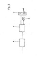
- Fig. 2 ein Blockschaltbild einer Anzeigevorrichtung gemäß Figur 1,
- Fig. 3 eine ausschnittsweise Darstellung einer ersten Ausführungsform der Anzeigevorrichtung und
- Fig. 4 eine ausschnittsweise Darstellung einer zweiten Ausführungsform der Anzeigevorrichtung.
- 1 is a partial representation of a basic embodiment of a display device according to the invention,
- 2 shows a block diagram of a display device according to FIG. 1,
- 3 shows a detail of a first embodiment of the display device and
- Fig. 4 is a partial representation of a second embodiment of the display device.
Auf einem Steuertisch 1 eines zentralen Fernsteuerplatzes sind entsprechend der Anzahl der einzelnen Farbzonen eines nicht näher dargestellten und beschriebenen Farbwerkes zonale Leuchtdiodenanzeigen in Form vertikaler Leuchtdiodenreihen 2 angeordnet, wobei jeder Farbzone eine entsprechend der gewünschten Anzeigegenauigkeit große Anzahl von Leuchtdioden 3 mit steigenden Ordnungsnummern 4 zugeordnet sein kann. In der dargestellten Grundausführung einer Anzeigevorrichtung gemäß Figur 1 besteht eine vertikale Leuchtdiodenreihe 2 aus jeweils zwanzig übereinander angeordneten einzelnen Leuchtdioden 3.On a control table 1 of a central remote control station, zonal light-emitting diode displays in the form of vertical light-
Unterhalb der Leuchtdiodenreihen sind Bedienungselemente in Form von Tasten 5 angeordnet, mit denen der Steuerbefehl für eine Verringerung oder Erhöhung der zonalen Farbmengen ausgelöst werden kann.Operating elements in the form of
Oberhalb der Leuchtdioden sind diesen übergeordnet digitale Signalgeber in Form numerischer Displays 6 vorgesehen. Statt der numerischen Displays 6 können auch andere optische Anzeigen, wie z. B. Blitzlampen oder akustische Signalgeber in Form von Signalhörnern oder Tickern vorgesehen werden.Above the light-emitting diodes, these higher-level digital signal transmitters are provided in the form of
Die Figur 1 stellt einen Ausschnitt aus dem Steuertisch 1 des zentralen Fernsteuerplatzes für die Farbzonenverstellung auszugsweise über einen Bereich von vier Farbzonen dar. Die Verbindung der Leuchtpunkte aller aktivierter Leuchtdioden 3 markiert über die Breite des Steuertisches 1 hinweg das Farbprofil 7 als qualitative Grobaussage über die tatsächlich vorhandene momentane Farbgebung. In der dargestellten Grundausführung mit je zwanzig vertikalen Leuchtdioden 3 pro Farbzonenanzeige wird das Farbprofil 7 von links nach rechts durch die achte, elfte, zehnte und sechste Leuchtdiode 3 markiert. Somit ist das Farbprofil in dem dargestellten Ausschnitt hinreichend bestimmt.1 shows a section of the control table 1 of the central remote control station for the color zone adjustment in part over a range of four color zones. The connection of the light points of all activated light-
Wie im Blockschaltbild der Figur 2 schematisch dargestellt, wird die zu messende Stellgröße mittels eines Gebers 8, z. B. ein allgemein gebräuchliches Potentiometer, direkt erfaßt und von diesem einem nachgeschalteten Signalwandler 9, in diesem Fall ein Analog-Digital-Wandler, als analoges Eingangssignal zugeführt. Der Signalwandler 9 setzt den Analogwert des Eingangssignals in einen entsprechenden,zur Anzeige verwendbaren Digitalwert um. Unmittelbar vom Signalwandler 9 gehen parallel zueinander eine Grobanzeige und eine Feinanzeige ab. Das umgesetzte Anzeigesignal wird, je nach dessen Wert, alleine der Grobanzeige oder zusätzlich auch der Feinanzeige zugeführt, die beide einen jeweils unterschiedlichen Auflösungsgrad aufweisen.As shown schematically in the block diagram of Figure 2, the manipulated variable to be measured is by means of an
Wenn der Wert des Anzeigesystems im Bereich zwischen unterer und oberer Ansprechschwelle einer der Leuchtdioden 3 einer zonalen, vertikalen Leuchtdiodenreihe 2 liegt, wird dieses Anzeigesignal in der Grobanzeige durch Aktivieren einer Leuchtdiode 3 sichtbar. Durch das simultane Aufleuchten je einer Leuchtdiode 3 verschiedener Zonen ergibt sich eine analoge Darstellung für das Farbprofil. Entsprechend dem Auflösungsgrad für dieses Anzeigesignal, der durch die Größe des Bereiches innerhalb der Ansprechschwellen der Leuchtdioden 3 bestimmt ist, liefert dieses Signal eine Grobinformation.If the value of the display system lies in the range between the lower and upper response threshold of one of the light-
Über die Zwischenwerte des Signals innerhalb der Ansprechschwellen einer Leuchtdiode 3 gibt die jeweils aktivierte Leuchtdiode 3 keine Auskunft. Um diese Zwischenwerte zusätzlich zur Grobinformation zur Anzeige zu bringen, wird die zusätzliche Feinanzeige benutzt. Dabei wird der die untere Ansprechschwelle einer Leuchtdiode 3 überschreitende Wert des Anzeigesignals dem numerischen Display 6 zugeführt und in digitalen Ziffern zur Feinanzeige gebracht. Der Auflösungsgrad dieser digitalen Feinanzeige ist erheblich größer als der der analogen Grobanzeige für das Farbprofil.The activated light-
Die Leuchtdiode 3 bleibt entsprechend der eingefahrenen Stellung des Stellgliedes aktiviert; die dazugehörige Ziffernanzeige leuchtet auf. So bedeutet z. B. die Ziffernanzeige im dritten numerischen Display 6 von links, daß das Stellglied für die zugeordnete Farbzone bei dezimaler Aufteilung um den Wert 0,2 über den der zehnten Leuchtdiode 3 zugeordneten Zahlenwert hinaus für die Farbgebung geöffnet ist. Die Ziffer Null im ersten numerischen Display 6 besagt, daß hier genau der Signalwert für die untere Ansprechschwelle der sechsten Leuchtdiode 3 vorliegt.The
In der Regel reicht eine einzige Dezimalstelle in der Ziffernanzeige aus. Die damit erzielte Genauigkeit entspricht höchstens Farbgüteanforderungen an das Druckprodukt. Statt der Ziffernanzeige kann auch ein anderer digitaler, optisch arbeitender Signalgeber 6 vorgesehen werden, wobei die Zahl der ausgesandten Impulse, z. B. Lichtblitze, ein Maß für den durch die Leuchtdiode 3 noch nicht erfaßten Zwischenwert des Anzeigesignales darstellt.As a rule, a single decimal place on the numerical display is sufficient. The accuracy achieved with this corresponds at most to color quality requirements for the printed product. Instead of the numerical display, another digital, optically operating
Eine Vereinfachung zur Durchführung des Anzeigeverfahrens ergibt sich in besonders vorteilhafter Weise dadurch, daß die für die Grobanzeige des Farbprofils 7 bereits vorhandenen Leuchtdioden 3 gleichzeitig auch für die Feinanzeige ausgenutzt werden, so daß sich eine zusätzliche Anzeige vollkommen erübrigt.A simplification for carrying out the display method results in a particularly advantageous manner in that the light-emitting
Gemäß der Darstellung in Figur 3 sind bei einer vorzugsweisen Ausführungsform der Anzeigevorrichtung jeweils sechzehn übereinander angeordnete einzelne Leuchtdioden 3 zu einer vertikalen Leuchtdiodenreihe 2 zusammengefaßt. Wie in dieser Figur angedeutet, wird die Anzeige derart durchgeführt, daß die für die analoge Grobanzeige des Farbprofils 7 aktivierte Leuchtdiode 3 mit gleicher Intensität dauernd glimmt, während eine weitere Leuchtdiode 3 derselben Leuchtdiodenreihe 2 mit anderer Ordnungsnummer 4 durch impulsartiges Blinken oder durch schwächeres Glimmen, d. h. Aufleuchten mit geringerer Intensität, die zusätzliche Information für die Stellgrößen zu deren Feineinstellung in digitaler Form liefert.According to the illustration in FIG. 3, in a preferred embodiment of the display device, sixteen individual light-emitting
So bedeutet z. B. ein konstantes Aufleuchten der achten Leuchtdiode 3 und ein impulsartiges Blinken der zwölften Leuchtdiode 3 in der ersten Leuchtdiodenreihe 2 von links, daß das Stellglied für die zugeordnete Farbzone um den Wert 12/16 über den unteren Ansprechwert der achten Leuchtdiode 3 hinaus geöffnet ist.So z. B. a constant lighting of the
Ein in Figur 4 dargestelltes zweites Ausführungsbeispiel der Anzeigevorrichtung zeigt den gleichen Aufbau wie das zuvor beschriebene der Figur 3, wobei die analoge Grobanzeige des Farbprofils 7 ebenfalls in gleicher Weise erfolgt.A second exemplary embodiment of the display device shown in FIG. 4 shows the same structure as that described in FIG. 3, the rough analog display of the color profile 7 likewise taking place in the same way.
Der wesentliche Unterschied dieses zweiten Ausführungsbeispiels gegenüber dem ersten besteht darin, daß der Auflösungsgrad der digitalen Feinanzeige durch die Möglichkeit der Ansteuerung entweder einer oder gleichzeitig zweier aufeinanderfolgender Leuchtdioden 3 einer Leuchtdiodenreihe 2 verdoppelt worden ist. Das gleichzeitige Aufblinken zweier aufeinanderfolgender Leuchtdioden 3 signalisiert noch zusätzlich einen mittig zwischen den beiden blinkenden Leuchtdioden 3 liegenden Zwischenwert.The main difference of this second exemplary embodiment from the first is that the degree of resolution of the digital fine display has been doubled by the possibility of activating either one or two successive light-emitting
Ein konstantes Aufleuchten der elften Leuchtdiode 3 und ein simultanes impulsartiges Blinken der siebten und achten Leuchtdiode 3 in der zweiten Leuchtdiodenreihe 2 von links der Figur 4 besagt, daß das dieser Farbzone zugeordnete Stellglied um den Wert 15/32 der Spanne von Leuchtdiode 3 zu Leuchtdiode 3 über den unteren Ansprechwert der achten Leuchtdiode 3 hinaus geöffnet ist.A constant lighting up of the
Durch die Ansteuerung der sechzehn Leuchtdioden in der beschriebenen Weise können somit 16 x 32 = 612 Einzelstellungen des Stellgliedes angezeigt werden. Eine Anzeige mit derart großem Auflösungsgrad wird auch höchsten Güteanforderungen an die Farbqualität des Druckproduktes gerecht.By controlling the sixteen LEDs in the manner described, 16 x 32 = 612 individual positions of the actuator can thus be displayed. A display with such a high degree of resolution also meets the highest quality requirements for the color quality of the printed product.
Die Erfindung ist natürlich keinesfalls auf die in den Figuren dargestellten und in der Beschreibung niedergelegten Ausführungsformen beschränkt, die lediglich als die Erfindung nicht begrenzende Beispiele anzusehen sind. Es versteht sich von selbst, daß auch andere Ausführungsformen mit zahlreichen Abwandlungen hinsichtlich baulicher Einzelheiten denkbar sind, wie z. B. die Erhöhung der Ablesegenauigkeit durch Anzeige mehrerer Dezimalstellen oder unterschiedlicher farblicher Abstimmung der Leuchtdioden 3 zur besseren Unterscheidung zwischen Grob- und Feinanzeige.The invention is of course in no way limited to the embodiments shown in the figures and laid down in the description, which are only to be regarded as examples which do not limit the invention. It goes without saying that other embodiments with numerous modifications with regard to structural details are conceivable, such as. B. the increase in reading accuracy by displaying several decimal places or different color matching of the
- 1 Steuertisch1 control table
- 2 Leuchtdiodenreihe2 row of LEDs
- 3 Leuchtdiode3 LEDs
- 4 Ordnungsnummer4 order number
- 5 Taste5 button
- 6 numerisches Display6 numerical display
- 7 Farb- und/oder Feuchteprofil7 color and / or moisture profile
- 8 Geber8 donors
- 9 Signalwandler9 signal converters
Claims (14)
dadurch gekennzeichnet,
daß dieselben Anzeigesignale verwendet werden für zwei voneinander getrennte Anzeigen,
von denen die eine als analoge Grobanzeige des Farb- und/oder Feuchteprofils vorgesehen ist, die den Grundwert für die Stellgrößen zur Grobeinstellung der Stellglieder liefert und die andere als digitale Feinanzeige, die den Zwischenwert für die Stellgrößen zur Feineinstellung der Stellglieder aufzeigt.1. A method for displaying manipulated variables of remote-controlled, zonal actuators for dosing the ink and / or moisture control at a central remote control station of a rotary printing press, the manipulated variables being converted into display signals and the display signals for displaying the color and / or moisture profile (7) by means of individual ones Light-emitting diodes (3) associated with color and / or wet zones are made visible,
characterized,
that the same display signals are used for two separate displays,
One of which is provided as an analog rough display of the color and / or moisture profile, which provides the basic value for the manipulated variables for the rough adjustment of the actuators and the other as a digital fine display, which shows the intermediate value for the manipulated variables for fine adjustment of the actuators.
dadurch gekennzeichnet,
daß die analoge Grobanzeige mittels vertikaler, zonaler Leuchtdiodenreihen (2) und
die digitale Feinanzeige mittels eines einer jeden Leuchtdiodenreihe (2) zusätzlich zugeordneten digitalen Signalgebers (6) erfolgt.2. The method according to claim 1,
characterized,
that the rough analog display by means of vertical, zonal LED rows (2) and
the digital fine display takes place by means of a digital signal transmitter (6) additionally assigned to each row of light-emitting diodes (2).
dadurch gekennzeichnet,
daß der digitale Signalgeber (6) optisch arbeitet.3. The method according to claim 1 and 2,
characterized,
that the digital signal generator (6) works optically.
dadurch gekennzeichnet,
daß der digitale Signalgeber (6) akustisch arbeitet.4. The method according to claim 1 and 2,
characterized,
that the digital signal generator (6) works acoustically.
dadurch gekennzeichnet,
daß beide Anzeigen, sowohl die analoge Grobanzeige als auch die digitale Feinanzeige,mittels der zonalen Leuchtdioden (3) vorgenommen werden,
wobei die Feinanzeige der Grobanzeige in den zonalen Leuchtdiodenreihen (2) überlagert ist.5. The method according to claim 1,
characterized,
that both displays, both the analog rough display and the digital fine display, are made by means of the zonal light-emitting diodes (3),
the fine display of the rough display being superimposed in the zonal light-emitting diode rows (2).
dadurch gekennzeichnet,
daß die analoge Grobanzeige durch konstantes Aufleuchten und die digitale Feinanzeige gleichzeitig durch impulsartiges Blinken einzelner Leuchtdioden (3) der zonalen Leuchtdiodenreihen (2) erfolgt.6. The method according to claim 1 and 5,
characterized,
that the rough analog display by constant lighting and the digital fine display at the same time by pulsing individual LEDs (3) of the zonal rows of LEDs (2).
dadurch gekennzeichnet,
daß die digitale Feinanzeige durch impulsartiges Blinken einer einzelnen oder gleichzeitig jeweils zweier aufeinanderfolgender Leuchtdioden (3) einer Leuchtdiodenreihe (2) erfolgt.7. The method according to claim 1, 5 and 6,
characterized,
that the digital fine display is carried out by pulsing a single or simultaneously two successive LEDs (3) of a row of LEDs (2).
dadurch gekennzeichnet,
daß bei Überschreiten eines der Anzeigesignale über die Ansprechschwelle einer Leuchtdiode (3) einer der zonalen Leuchtdiodenreihen (2) hinaus, der zwischen dieser und der Ansprechschwelle der nächst höheren Leuchtdiode (3) liegende, analog noch nicht verarbeitungsfähige Zwischenwert des Anzeigesignals der digitalen Feinanzeige zugeführt wird.8. The method according to claim 1 to 7,
characterized,
that when one of the display signals is exceeded via the response threshold of a light-emitting diode (3) one of the zonal light-emitting diode rows (2), which is fed between this and the response threshold of the next higher light-emitting diode (3), analog not yet processable intermediate value of the display signal of the digital fine display.
dadurch gekennzeichnet,
daß der Zwischenwert für die Stellgrößen zur Feineinstellung der Stellglieder in der Feinanzeige als Absolutwert bezogen auf eine wählbare Nullinie angezeigt wird.9. The method according to claim 1 to 8,
characterized,
that the intermediate value for the manipulated variables for fine adjustment of the actuators is shown in the fine display as an absolute value based on a selectable zero line.
dadurch gekennzeichnet,
daß der Zwischenwert für die Stellgrößen zur Feineinstellung für die Stellglieder in der Feinanzeige als Differenzwert zwischen zwei Leuchtdioden (3) aufeinanderfolgender Ordnungsnummer (4) einer zonalen Leuchtdiodenreihe (2) sichtbar gemacht wird.10. The method according to claim 1 to 9,
characterized,
that the intermediate value for the manipulated variables for fine adjustment for the actuators is made visible in the fine display as the difference between two light-emitting diodes (3) of consecutive order number (4) of a zonal light-emitting diode row (2).
dadurch gekennzeichnet,
daß zur analogen Grobanzeige des Farb- und/oder Feuchteprofils (7) als Grundwert für die Stellgrößen zur Grobeinstellung der Stellglieder vertikale Leuchtdiodenreihen (2) und
als digitale Feinanzeige zur Signalisierung der analog noch nicht anzeigbaren Zwischenwerte der Anzeigesignale zur Feineinstellung der Stellglieder digitale Signalgeber (6) vorgesehen sind.11. An apparatus for performing the method according to claims 1 to 4 and 8 to 10, with devices (8,9) for measuring manipulated variables of zonal actuators, for converting the manipulated variables into display signals and for making the display signals visible to display the color and / or moisture profile (7) by means of light-emitting diodes (3) assigned to individual color and / or wet zones at a central remote control station,
characterized,
that for the analog rough display of the color and / or moisture profile (7) as the basic value for the manipulated variables for the rough adjustment of the actuators vertical rows of LEDs (2) and
as a digital fine display for signaling the intermediate values of the display signals for fine adjustment that cannot yet be displayed analogously the actuators digital signal transmitters (6) are provided.
dadurch gekennzeichnet,
daß die digitalen Signalgeber als einer jeden zonalen Leuchtdiodenreihe (2) zugeordnete, oberhalb derselben angeordnete numerische Displays (6) ausgebildet sind.12. The device according to claim 11,
characterized,
that the digital signal transmitters are designed as numerical displays (6) which are assigned to each row of light-emitting diodes (2) and are arranged above them.
dadurch gekennzeichnet, daß sowohl für die analoge Grobanzeige des Farb- und/oder Feuchteprofils (7) als Grundwert für die Stellgrößen zur Grobeinstellung der Stellglieder als auch für die digitale Feinanzeige zur Signalisierung der analog noch nicht anzeigbaren Zwischenwerte der Anzeigesignale zur Feineinstellung der Stellglieder dieselben vertikalen Leuchtdiodenreihen (2) vorgesehen sind,
wobei für die analoge Grobanzeige konstant aufleuchtende und für die dieser überlagerte digitale Feinanzeige impulsartig blinkende Leuchtdioden (3) zur Anwendung kommen.13. An apparatus for performing the method according to claim 1 and 5 to 10, with devices (8, 9) for measuring manipulated variables of zonal actuators, for converting the manipulated variables into display signals and for making the display signals visible to display the color and / or moisture profile ( 7) by means of light-emitting diodes (3) assigned to individual color and / or wet zones at a central remote control station,
characterized in that both for the analog rough display of the color and / or moisture profile (7) as the basic value for the manipulated variables for the rough setting of the actuators and for the digital fine display for signaling the intermediate values of the display signals for the fine adjustment of the actuators which cannot yet be displayed for the same adjustment Rows of LEDs (2) are provided,
whereby for the rough analog display and permanently flashing light emitting diodes (3) are used for the superimposed digital fine display.
gekennzeichnet durch
eine Verdoppelung des Auflösungsgrades der digitalen Feinanzeige infolge impulsartigen Blinkens einer oder gleichzeitig zweier aufeinanderfolgender Leuchtdioden (3) einer Leuchtdiodenreihe (2).14. The apparatus according to claim 11,
marked by
a doubling of the degree of resolution of the digital fine display due to the pulse-like flashing of one or two successive LEDs (3) of a row of LEDs (2).
Priority Applications (1)
| Application Number | Priority Date | Filing Date | Title |
|---|---|---|---|
| AT79101890T ATE2494T1 (en) | 1978-07-08 | 1979-06-11 | PROCEDURE FOR DISPLAYING VARIABLES FOR CONTROLLING A ROTARY PRESS. |
Applications Claiming Priority (2)
| Application Number | Priority Date | Filing Date | Title |
|---|---|---|---|
| DE2830085 | 1978-07-08 | ||
| DE2830085A DE2830085C3 (en) | 1978-07-08 | 1978-07-08 | Method and device for displaying manipulated variables |
Publications (2)
| Publication Number | Publication Date |
|---|---|
| EP0007009A1 true EP0007009A1 (en) | 1980-01-23 |
| EP0007009B1 EP0007009B1 (en) | 1983-02-16 |
Family
ID=6043888
Family Applications (1)
| Application Number | Title | Priority Date | Filing Date |
|---|---|---|---|
| EP79101890A Expired EP0007009B1 (en) | 1978-07-08 | 1979-06-11 | Method for displaying the magnitude of remote control signals for a rotary press |
Country Status (13)
| Country | Link |
|---|---|
| US (1) | US4903596A (en) |
| EP (1) | EP0007009B1 (en) |
| JP (2) | JPS5512495A (en) |
| AT (1) | ATE2494T1 (en) |
| AU (1) | AU527495B2 (en) |
| BR (1) | BR7904306A (en) |
| CA (1) | CA1148284A (en) |
| DE (1) | DE2830085C3 (en) |
| DK (1) | DK146380C (en) |
| ES (2) | ES482202A1 (en) |
| MX (1) | MX153236A (en) |
| NO (1) | NO151852C (en) |
| ZA (1) | ZA793044B (en) |
Cited By (2)
| Publication number | Priority date | Publication date | Assignee | Title |
|---|---|---|---|---|
| EP0095649B1 (en) * | 1982-05-29 | 1987-08-12 | Heidelberger Druckmaschinen Aktiengesellschaft | Ink feed control device for a printing press |
| EP0243697A2 (en) * | 1986-04-30 | 1987-11-04 | Heidelberger Druckmaschinen Aktiengesellschaft | Method of adjusting regulating units in printing machines |
Families Citing this family (11)
| Publication number | Priority date | Publication date | Assignee | Title |
|---|---|---|---|---|
| JPS57158953A (en) * | 1981-03-25 | 1982-09-30 | Yuasa Battery Co Ltd | Paste type plate for storage battery |
| DE3112189A1 (en) * | 1981-03-27 | 1982-10-14 | Heidelberger Druckmaschinen Ag, 6900 Heidelberg | PRINTING MACHINE WITH ACTUATORS |
| DE3147312A1 (en) * | 1981-11-28 | 1983-06-09 | Heidelberger Druckmaschinen Ag, 6900 Heidelberg | ADJUSTMENT DEVICE FOR A PRINTING MACHINE |
| US4607571A (en) * | 1982-12-21 | 1986-08-26 | Dai Nippon Insatsu Kabushiki Kaisha | Method for adjusting an ink fountain in a printing press and ink fountains |
| JPS63120653A (en) * | 1986-11-10 | 1988-05-25 | Kinnosuke Ota | Automatic dust remover for plate face of printing press |
| JPS6390120U (en) * | 1986-12-03 | 1988-06-11 | ||
| JPS63230343A (en) * | 1987-03-19 | 1988-09-26 | Toshiba Seiki Kk | Ink supply amount control apparatus of printing press |
| US5832830A (en) * | 1995-01-10 | 1998-11-10 | Heidelberger Druckmaschinen Ag | Method and apparatus for normalizing the display of ink key zero points in an ink fountain |
| JP3062167B2 (en) * | 1998-11-20 | 2000-07-10 | 株式会社東京機械製作所 | Plate mounting position indicating device |
| JP4847113B2 (en) * | 2005-11-30 | 2011-12-28 | 柳井紙工株式会社 | Assembled paper box |
| JP2008037046A (en) * | 2006-08-09 | 2008-02-21 | Mitsubishi Heavy Ind Ltd | Operation desk of printer |
Citations (9)
| Publication number | Priority date | Publication date | Assignee | Title |
|---|---|---|---|---|
| DE1623873A1 (en) * | 1967-06-02 | 1970-10-29 | Vdo Schindling | Device for displaying measured values |
| FR2067650A5 (en) * | 1969-11-12 | 1971-08-20 | Marinoni | |
| DE2141355A1 (en) * | 1970-08-19 | 1972-02-24 | Strachan & Henshaw Ltd | Adjustment mechanism for printing ink supply device and printing ink supply device with such an adjusting mechanism |
| FR2214130A1 (en) * | 1973-01-17 | 1974-08-09 | Sintra | |
| US3930447A (en) * | 1974-07-22 | 1976-01-06 | Harris Corporation | Dual purpose display for printing presses |
| US3990799A (en) * | 1974-01-14 | 1976-11-09 | Minolta Camera Kabushiki Kaisha | Digital exposure meter |
| US4008664A (en) * | 1973-07-23 | 1977-02-22 | Harris-Intertype Corporation | Ink key control system |
| US4014011A (en) * | 1975-04-25 | 1977-03-22 | Hewlett-Packard Company | Variable resolution display |
| BE868221A (en) * | 1977-06-18 | 1978-10-16 | Heidelberger Druckmasch Ag | DEVICE FOR CONTROLLING THE DRIVE OF INKING IN ROTARY PRINTING PRESSES |
Family Cites Families (17)
| Publication number | Priority date | Publication date | Assignee | Title |
|---|---|---|---|---|
| DE7228918U (en) * | 1973-10-04 | Maschinenfabrik Augsburg Nuernberg Ag | Equipment on inking units of printing machines | |
| DD85081A (en) * | ||||
| FR85705E (en) * | 1964-01-22 | 1965-10-01 | Electronique Et D Automatique | Method for controlling the relative position of a fixed part and a rotating member |
| US3644784A (en) * | 1970-04-16 | 1972-02-22 | Honeywell Inc | Solid-state indicator displays |
| US3689835A (en) * | 1970-09-10 | 1972-09-05 | Veeder Industries Inc | Analog/digital meter having front indicator means overlying a rear indicator means |
| US3726250A (en) * | 1971-03-18 | 1973-04-10 | Marconi Co Canada | Indicator |
| JPS542116B1 (en) * | 1971-06-26 | 1979-02-02 | ||
| US3772874A (en) * | 1971-12-09 | 1973-11-20 | Princeton Materials Science | Display apparatus and chronometer utilizing optically variable liquid |
| US3771015A (en) * | 1972-02-09 | 1973-11-06 | Beckman Instruments Inc | Light-emitting diode display |
| US3825827A (en) * | 1972-04-13 | 1974-07-23 | Bendix Corp | Columnar display for electrical signals with digital signal limit set |
| JPS5121370B2 (en) * | 1972-05-26 | 1976-07-02 | ||
| DE2331660B2 (en) * | 1973-06-22 | 1977-02-03 | Robert Bosch Gmbh, 7000 Stuttgart | CIRCUIT ARRANGEMENT FOR DISPLAYING DC VOLTAGE USING ELECTRO-OPTICAL DISPLAY ELEMENTS |
| US3925770A (en) * | 1974-07-29 | 1975-12-09 | Business Electronics Inc | Audible signaling device for a computer |
| JPS5121370U (en) * | 1974-08-03 | 1976-02-17 | ||
| DE2514167B2 (en) * | 1975-03-29 | 1977-04-28 | Schenk, Christoph, Dipl.-Phys., 8551 Adelsdorf | CONTROL CIRCUIT FOR QUASI-ANALOGUE LIGHT BAND DISPLAY |
| US4155084A (en) * | 1977-09-08 | 1979-05-15 | The United States Of America As Represented By The Secretary Of The Navy | Solid state LED display device |
| DE2744946A1 (en) * | 1977-10-06 | 1979-04-19 | Hartmann & Braun Ag | Display unit for measured data - uses luminous cells next to one another with position of single illuminated cell serving as indication criterion |
-
1978
- 1978-07-08 DE DE2830085A patent/DE2830085C3/en not_active Expired
-
1979
- 1979-06-11 AT AT79101890T patent/ATE2494T1/en not_active IP Right Cessation
- 1979-06-11 EP EP79101890A patent/EP0007009B1/en not_active Expired
- 1979-06-19 ZA ZA793044A patent/ZA793044B/en unknown
- 1979-06-29 NO NO792192A patent/NO151852C/en unknown
- 1979-07-04 ES ES482202A patent/ES482202A1/en not_active Expired
- 1979-07-05 DK DK285179A patent/DK146380C/en active
- 1979-07-06 BR BR7904306A patent/BR7904306A/en not_active IP Right Cessation
- 1979-07-06 CA CA000331347A patent/CA1148284A/en not_active Expired
- 1979-07-09 JP JP8600979A patent/JPS5512495A/en active Pending
- 1979-07-09 AU AU48790/79A patent/AU527495B2/en not_active Ceased
- 1979-07-09 MX MX178396A patent/MX153236A/en unknown
-
1980
- 1980-04-15 ES ES490579A patent/ES8100970A1/en not_active Expired
-
1983
- 1983-04-22 JP JP1983059528U patent/JPS594424U/en active Granted
-
1987
- 1987-09-14 US US07/096,595 patent/US4903596A/en not_active Expired - Lifetime
Patent Citations (11)
| Publication number | Priority date | Publication date | Assignee | Title |
|---|---|---|---|---|
| DE1623873A1 (en) * | 1967-06-02 | 1970-10-29 | Vdo Schindling | Device for displaying measured values |
| FR2067650A5 (en) * | 1969-11-12 | 1971-08-20 | Marinoni | |
| DE2141355A1 (en) * | 1970-08-19 | 1972-02-24 | Strachan & Henshaw Ltd | Adjustment mechanism for printing ink supply device and printing ink supply device with such an adjusting mechanism |
| FR2214130A1 (en) * | 1973-01-17 | 1974-08-09 | Sintra | |
| US4008664A (en) * | 1973-07-23 | 1977-02-22 | Harris-Intertype Corporation | Ink key control system |
| US3990799A (en) * | 1974-01-14 | 1976-11-09 | Minolta Camera Kabushiki Kaisha | Digital exposure meter |
| US3930447A (en) * | 1974-07-22 | 1976-01-06 | Harris Corporation | Dual purpose display for printing presses |
| US4014011A (en) * | 1975-04-25 | 1977-03-22 | Hewlett-Packard Company | Variable resolution display |
| BE868221A (en) * | 1977-06-18 | 1978-10-16 | Heidelberger Druckmasch Ag | DEVICE FOR CONTROLLING THE DRIVE OF INKING IN ROTARY PRINTING PRESSES |
| NL7806524A (en) * | 1977-06-18 | 1978-12-20 | Heidelberger Druckmasch Ag | DEVICE FOR CONTROLLING THE INK GUIDE TO ROTARY PRINTING MACHINES. |
| FR2394398A1 (en) * | 1977-06-18 | 1979-01-12 | Heidelberger Druckmasch Ag | INK SUPPLY CONTROL INSTALLATION IN ROTARY PRINTING MACHINES |
Cited By (3)
| Publication number | Priority date | Publication date | Assignee | Title |
|---|---|---|---|---|
| EP0095649B1 (en) * | 1982-05-29 | 1987-08-12 | Heidelberger Druckmaschinen Aktiengesellschaft | Ink feed control device for a printing press |
| EP0243697A2 (en) * | 1986-04-30 | 1987-11-04 | Heidelberger Druckmaschinen Aktiengesellschaft | Method of adjusting regulating units in printing machines |
| EP0243697A3 (en) * | 1986-04-30 | 1989-05-10 | Heidelberger Druckmaschinen Aktiengesellschaft | Method of adjusting regulating units in printing machines |
Also Published As
| Publication number | Publication date |
|---|---|
| NO792192L (en) | 1980-03-24 |
| AU4879079A (en) | 1980-01-17 |
| US4903596A (en) | 1990-02-27 |
| DE2830085A1 (en) | 1980-01-17 |
| ES490579A0 (en) | 1980-12-01 |
| MX153236A (en) | 1986-09-02 |
| NO151852C (en) | 1985-06-19 |
| JPS594424U (en) | 1984-01-12 |
| ES482202A1 (en) | 1980-07-01 |
| EP0007009B1 (en) | 1983-02-16 |
| DE2830085B2 (en) | 1980-07-17 |
| DK146380B (en) | 1983-09-26 |
| DK285179A (en) | 1980-01-09 |
| JPH0114885Y2 (en) | 1989-05-02 |
| DE2830085C3 (en) | 1986-07-10 |
| ZA793044B (en) | 1980-07-30 |
| ES8100970A1 (en) | 1980-12-01 |
| JPS5512495A (en) | 1980-01-29 |
| DK146380C (en) | 1984-03-05 |
| ATE2494T1 (en) | 1983-03-15 |
| NO151852B (en) | 1985-03-11 |
| BR7904306A (en) | 1980-04-01 |
| AU527495B2 (en) | 1983-03-10 |
| CA1148284A (en) | 1983-06-14 |
Similar Documents
| Publication | Publication Date | Title |
|---|---|---|
| EP0095649B1 (en) | Ink feed control device for a printing press | |
| EP0007009A1 (en) | Method for displaying the magnitude of remote control signals for a rotary press | |
| DE3331208C2 (en) | ||
| EP0266515A2 (en) | Method and apparatus for register correction | |
| DE2727426A1 (en) | DEVICE FOR CONTROLLING THE COLOR GUIDE ON ROTARY PRINTING MACHINES | |
| EP0356705B1 (en) | Data reading unit for an ink control devices | |
| DE2947791A1 (en) | DEVICE FOR COLOR MONITORING OF SHEET OR SHAPED MATERIALS IN MOTION, IN PARTICULAR THE PRINTING MATERIALS OF PRINTING MATERIALS OF PRINTING MACHINES | |
| DE3625518C2 (en) | ||
| CH667617A5 (en) | CONTROL DEVICE FOR AN ACTUATOR ON A PRINTING MACHINE. | |
| EP0860276B1 (en) | Device and method for quality control | |
| EP0123257A2 (en) | Method and device for regulating the ink supply in the inking units of multicolour printing machines | |
| DE3104573C2 (en) | ||
| DE3942254C2 (en) | ||
| DE2449287A1 (en) | METROLOGICAL DEVICE | |
| DE3024452A1 (en) | DEVICE FOR DISPLAYING THE ELECTRICALLY DETECTABLE POSITIONS OR SETTINGS OF INDIVIDUAL EQUIPMENT REQUIRED FOR THE PRINTING PROCESS | |
| DE3334019A1 (en) | METHOD AND DEVICE FOR ADJUSTING THE DOSING ORGANS ASSIGNED TO THE COLOR ZONES OF A COLORING PLANT | |
| DE2164351C2 (en) | Display device for the position of the zone screws of the ink knife of an ink fountain of a printing press | |
| DE1671439A1 (en) | Arrangement for measuring the current on the individual electrodes of electrolytic cells | |
| DE2238007A1 (en) | DEVICE FOR CONTROLLING THE CONSTANCE OF COLORING OF PRINT SHEETS | |
| DE2301393A1 (en) | METHOD AND DEVICE FOR ANALYSIS OF A DOCUMENT FOR DETERMINING SCREEN TONE VALUES FOR REPRODUCTION USING THE PRINT CHARACTERISTICS OF A PRINTING INK SCALE OR DGL | |
| DE729673C (en) | Device for determining the relative position of the images or print marks of paper or fabric webs | |
| DE3328810C2 (en) | ||
| DE3102377A1 (en) | Remote adjustment system for inking units | |
| EP0136520A2 (en) | Apparatus for recording densitometric values of a control strip | |
| DE3030266A1 (en) | Analogue chart recorder with alphanumeric printer - embodies data preparation circuit assembling annotation data for synchronised printing |
Legal Events
| Date | Code | Title | Description |
|---|---|---|---|
| PUAI | Public reference made under article 153(3) epc to a published international application that has entered the european phase |
Free format text: ORIGINAL CODE: 0009012 |
|
| AK | Designated contracting states |
Designated state(s): AT BE CH FR GB IT NL SE |
|
| 17P | Request for examination filed | ||
| ITF | It: translation for a ep patent filed |
Owner name: STUDIO JAUMANN |
|
| GRAA | (expected) grant |
Free format text: ORIGINAL CODE: 0009210 |
|
| AK | Designated contracting states |
Designated state(s): AT BE CH FR GB IT NL SE |
|
| REF | Corresponds to: |
Ref document number: 2494 Country of ref document: AT Date of ref document: 19830315 Kind code of ref document: T |
|
| ET | Fr: translation filed | ||
| PLBI | Opposition filed |
Free format text: ORIGINAL CODE: 0009260 |
|
| 26 | Opposition filed |
Opponent name: M.A.N.- ROLAND DRUCKMASCHINEN AKTIENGESELLSCHAFT Effective date: 19831105 |
|
| PLBI | Opposition filed |
Free format text: ORIGINAL CODE: 0009260 |
|
| 26 | Opposition filed |
Opponent name: KOENIG & BAUER AKTIENGESELLSCHAFT Effective date: 19831117 |
|
| PLBN | Opposition rejected |
Free format text: ORIGINAL CODE: 0009273 |
|
| STAA | Information on the status of an ep patent application or granted ep patent |
Free format text: STATUS: OPPOSITION REJECTED |
|
| 27O | Opposition rejected |
Effective date: 19860422 |
|
| NLR2 | Nl: decision of opposition | ||
| ITTA | It: last paid annual fee | ||
| PGFP | Annual fee paid to national office [announced via postgrant information from national office to epo] |
Ref country code: AT Payment date: 19920604 Year of fee payment: 14 |
|
| PGFP | Annual fee paid to national office [announced via postgrant information from national office to epo] |
Ref country code: SE Payment date: 19920615 Year of fee payment: 14 |
|
| PGFP | Annual fee paid to national office [announced via postgrant information from national office to epo] |
Ref country code: NL Payment date: 19920630 Year of fee payment: 14 |
|
| PG25 | Lapsed in a contracting state [announced via postgrant information from national office to epo] |
Ref country code: AT Effective date: 19930611 |
|
| PG25 | Lapsed in a contracting state [announced via postgrant information from national office to epo] |
Ref country code: SE Effective date: 19930612 |
|
| PG25 | Lapsed in a contracting state [announced via postgrant information from national office to epo] |
Ref country code: NL Effective date: 19940101 |
|
| NLV4 | Nl: lapsed or anulled due to non-payment of the annual fee | ||
| EUG | Se: european patent has lapsed |
Ref document number: 79101890.6 Effective date: 19940110 |
|
| PGFP | Annual fee paid to national office [announced via postgrant information from national office to epo] |
Ref country code: FR Payment date: 19950602 Year of fee payment: 17 |
|
| PGFP | Annual fee paid to national office [announced via postgrant information from national office to epo] |
Ref country code: BE Payment date: 19950608 Year of fee payment: 17 |
|
| PGFP | Annual fee paid to national office [announced via postgrant information from national office to epo] |
Ref country code: CH Payment date: 19950808 Year of fee payment: 17 |
|
| PGFP | Annual fee paid to national office [announced via postgrant information from national office to epo] |
Ref country code: GB Payment date: 19960520 Year of fee payment: 18 |
|
| PG25 | Lapsed in a contracting state [announced via postgrant information from national office to epo] |
Ref country code: CH Effective date: 19960630 Ref country code: BE Effective date: 19960630 |
|
| BERE | Be: lapsed |
Owner name: HEIDELBERGER DRUCKMASCHINEN A.G. Effective date: 19960630 |
|
| REG | Reference to a national code |
Ref country code: CH Ref legal event code: PL |
|
| PG25 | Lapsed in a contracting state [announced via postgrant information from national office to epo] |
Ref country code: FR Effective date: 19970228 |
|
| REG | Reference to a national code |
Ref country code: FR Ref legal event code: ST |
|
| PG25 | Lapsed in a contracting state [announced via postgrant information from national office to epo] |
Ref country code: GB Free format text: LAPSE BECAUSE OF NON-PAYMENT OF DUE FEES Effective date: 19970611 |
|
| GBPC | Gb: european patent ceased through non-payment of renewal fee |
Effective date: 19970611 |