EP0006342B1 - Device and method for folding self-sealing envelope flaps - Google Patents
Device and method for folding self-sealing envelope flaps Download PDFInfo
- Publication number
- EP0006342B1 EP0006342B1 EP79301115A EP79301115A EP0006342B1 EP 0006342 B1 EP0006342 B1 EP 0006342B1 EP 79301115 A EP79301115 A EP 79301115A EP 79301115 A EP79301115 A EP 79301115A EP 0006342 B1 EP0006342 B1 EP 0006342B1
- Authority
- EP
- European Patent Office
- Prior art keywords
- roller
- envelope
- flap
- main
- front panel
- Prior art date
- Legal status (The legal status is an assumption and is not a legal conclusion. Google has not performed a legal analysis and makes no representation as to the accuracy of the status listed.)
- Expired
Links
- 238000007789 sealing Methods 0.000 title claims description 12
- 238000000034 method Methods 0.000 title claims 3
- 239000000853 adhesive Substances 0.000 claims description 14
- 230000001070 adhesive effect Effects 0.000 claims description 14
- 210000002105 tongue Anatomy 0.000 description 7
- 239000010410 layer Substances 0.000 description 3
- 239000012790 adhesive layer Substances 0.000 description 2
- 230000000295 complement effect Effects 0.000 description 2
- 239000004816 latex Substances 0.000 description 2
- 229920000126 latex Polymers 0.000 description 2
- 229910000831 Steel Inorganic materials 0.000 description 1
- 230000001154 acute effect Effects 0.000 description 1
- 229920001971 elastomer Polymers 0.000 description 1
- 230000012447 hatching Effects 0.000 description 1
- 239000000463 material Substances 0.000 description 1
- 230000002093 peripheral effect Effects 0.000 description 1
- 239000010959 steel Substances 0.000 description 1
- 238000011144 upstream manufacturing Methods 0.000 description 1
Images

Classifications
-
- B—PERFORMING OPERATIONS; TRANSPORTING
- B65—CONVEYING; PACKING; STORING; HANDLING THIN OR FILAMENTARY MATERIAL
- B65H—HANDLING THIN OR FILAMENTARY MATERIAL, e.g. SHEETS, WEBS, CABLES
- B65H45/00—Folding thin material
- B65H45/12—Folding articles or webs with application of pressure to define or form crease lines
- B65H45/16—Rotary folders
- B65H45/162—Rotary folders with folding jaw cylinders
- B65H45/165—Details of sheet gripping means therefor
-
- B—PERFORMING OPERATIONS; TRANSPORTING
- B65—CONVEYING; PACKING; STORING; HANDLING THIN OR FILAMENTARY MATERIAL
- B65H—HANDLING THIN OR FILAMENTARY MATERIAL, e.g. SHEETS, WEBS, CABLES
- B65H45/00—Folding thin material
- B65H45/12—Folding articles or webs with application of pressure to define or form crease lines
- B65H45/14—Buckling folders
-
- B—PERFORMING OPERATIONS; TRANSPORTING
- B31—MAKING ARTICLES OF PAPER, CARDBOARD OR MATERIAL WORKED IN A MANNER ANALOGOUS TO PAPER; WORKING PAPER, CARDBOARD OR MATERIAL WORKED IN A MANNER ANALOGOUS TO PAPER
- B31B—MAKING CONTAINERS OF PAPER, CARDBOARD OR MATERIAL WORKED IN A MANNER ANALOGOUS TO PAPER
- B31B2150/00—Flexible containers made from sheets or blanks, e.g. from flattened tubes
-
- B—PERFORMING OPERATIONS; TRANSPORTING
- B31—MAKING ARTICLES OF PAPER, CARDBOARD OR MATERIAL WORKED IN A MANNER ANALOGOUS TO PAPER; WORKING PAPER, CARDBOARD OR MATERIAL WORKED IN A MANNER ANALOGOUS TO PAPER
- B31B—MAKING CONTAINERS OF PAPER, CARDBOARD OR MATERIAL WORKED IN A MANNER ANALOGOUS TO PAPER
- B31B2160/00—Shape of flexible containers
- B31B2160/10—Shape of flexible containers rectangular and flat, i.e. without structural provision for thickness of contents
-
- B—PERFORMING OPERATIONS; TRANSPORTING
- B31—MAKING ARTICLES OF PAPER, CARDBOARD OR MATERIAL WORKED IN A MANNER ANALOGOUS TO PAPER; WORKING PAPER, CARDBOARD OR MATERIAL WORKED IN A MANNER ANALOGOUS TO PAPER
- B31B—MAKING CONTAINERS OF PAPER, CARDBOARD OR MATERIAL WORKED IN A MANNER ANALOGOUS TO PAPER
- B31B70/00—Making flexible containers, e.g. envelopes or bags
- B31B70/26—Folding sheets, blanks or webs
- B31B70/261—Folding sheets, blanks or webs involving transversely folding, i.e. along a line perpendicular to the direction of movement
-
- Y—GENERAL TAGGING OF NEW TECHNOLOGICAL DEVELOPMENTS; GENERAL TAGGING OF CROSS-SECTIONAL TECHNOLOGIES SPANNING OVER SEVERAL SECTIONS OF THE IPC; TECHNICAL SUBJECTS COVERED BY FORMER USPC CROSS-REFERENCE ART COLLECTIONS [XRACs] AND DIGESTS
- Y10—TECHNICAL SUBJECTS COVERED BY FORMER USPC
- Y10S—TECHNICAL SUBJECTS COVERED BY FORMER USPC CROSS-REFERENCE ART COLLECTIONS [XRACs] AND DIGESTS
- Y10S493/00—Manufacturing container or tube from paper; or other manufacturing from a sheet or web
- Y10S493/916—Pliable container
- Y10S493/917—Envelope
- Y10S493/92—Envelope having plural compartments
Definitions
- This invention relates to machines for producing self-sealing envelopes, and more particularly to folding the flaps thereof into an inoperative condition.
- a self-sealing envelope has a main flap extension of the top edge of the front panel of the envelope and a secondary flap extension of the top edge of the back panel of the envelope, both flaps having an adhesive material (usually latex adhesive) applied to the same side, the main flap being foldable over the secondary flap so that the two layers of adhesive come into contact and seal the flaps together to close the envelope. Both flaps are foldable downwardly into an inoperative condition in which the adhesive surfaces lie face-to-face with surfaces of the envelope not having adhesive.
- a secondary flap of the back panel of the envelope carries the complementary layer of adhesive and is also foldable downwardly so as to keep this complementary layer out of contact with the adhesive on the main flap until such time as it is desired to close the envelope, whereupon the secondary flap is raised to expose the adhesive layer.
- Specification DE 2142155 discloses for use in a machine for producing self-sealing envelopes a device for folding the main and secondary flaps into the inoperative condition, the flaps having been previously coated with adhesive, the device comprising a roller for receiving a succession of envelopes with their bottom edges leading and their front panels in contact with the roller, suction means on the roller to apply suction to the main flap of the envelope and thereby secure it to the surface of the roller, abutment means adjacent the surface of the roller for engaging the front panel of the envelope as it lifts from the surface of the roller and temporarily arresting its movement with the roller whereby the main flap on being carried around with the roller folds relative to the front panel.
- the present invention provides such a machine in which first stop means are provided on the roller for arresting the bottom edge of an envelope and thereby defining its position on the roller, the suction means on the roller being spaced from the first stop means, said abutment means adjacent the roller initially supporting the envelope in a position relative to the surface of the roller so that as the main flap is carried around with the roller the upper edge of the secondary flap bears slidably upon the surface of the roller, and second stop means are provided on the roller for arresting the upper edge of the secondary flap when in said sliding engagement with the roller so as to carry it around the roller and thereby fold it relative to the back panel.
- Said abutment means preferably includes an element arranged so as to temporarily trap the bottom portion of the back panel of the envelope to maintain the envelope initially in said position, the bottom edge of the envelope moving free of the said element as the movement of the main flap with the roller draws the envelope around the portion of said abutment means which engages the front panel of the envelope.
- a conventional self-sealing envelope has a front panel 10 and back panel 12 secured together by side flaps 14.
- a main closure flap 16 is provided as an extension of the upper edge of the front panel 10
- a secondary closure flap 18 is provided as an extension of the upper edge of the back panel 12.
- a self-sealing latex adhesive Prior to folding of the closure flaps, they are each coated on the same side with a self-sealing latex adhesive, as indicated by the hatching in Fig. 1.
- the two closure flaps are folded downwardly as shown in Fig. 2, the adhesive layers lie face-to-face with portions of the envelope which do not carry adhesive.
- both closure flaps are raised, and then the main closure flap 16 is folded over onto the raised secondary closure flap 18 so that the two adhesive surfaces come into contact and adhere together.
- the device of the present invention is concerned with folding the closure flaps from the position shown in Fig. 1 to the position shown in Fig. 2, and effecting this folding at high speed as part of an envelope making machine.
- this device comprises a steel roller 20 which is driven so as to rotate in the direction of the arrow A.
- the roller is provided with internal ducting (not shown) for connection to a source of vacuum, the ducting being connected to openings on the surface of the roller.
- These openings are arranged as a leading band of openings 22 extending substantially continuously across the roller, and behind this leading band a series of groups 24 of openings spaced apart by unapertured regions.
- the total peripheral extent of the region having these suction openings 22, 24 is substantially the same as the width of the main flap 16 of the envelope.
- a wider region of suction openings may be provided to allow for different sizes of envelopes, and any openings which are not desired for a particular size of envelope can be blanked off.
- Behind the leading band 22 of openings and alternating with the groups 24 of openings the roller is provided with a row of secondary stop elements 28. Again, the circumferential setting of these stop elements can be adjusted.
- a bar 32 is closely spaced from the surface of the roller and extends parallel thereto.
- the bar carries a series of tongues 34 arranged so as to lie over the groups of apertures 24 and between the second stop elements 28 as the roller rotates.
- the bar 32 is pivotable to a small degree so that tongues can be raised and lowered as indicated by the double ended arrow B (see Fig. 4).
- a rubber surfaced roller 36 is located in contact with the roller 20 just before the bar 32.
- a further roller 38 which is slightly spaced from the surface of the roller 20.
- the roller 38 is provided with a series of circumferential grooves which freely receive extension elements 40 at the edge of a table 42.
- Extension elements 40 are curved so as to follow the curvature of the roller 38 within the circumferential grooves (see Fig. 4).
- a plate 44 which extends towards the roller 36 is inclined upwardly at an acute angle with respect to the table 42.
- the plate 44 is adjustably secured to the table by means of a screw clamp 46.
- the self-sealing envelopes are produced on a conventional machine, and adhesive is applied to the extended closure flaps to produce a succession of envelopes in the form shown in Fig. 1. These envelopes travel with their bottom edge leading, and are delivered towards the surface of the roller 20 on the upstream side of the nip with the roller 36. The bottom edge of the envelope (designated 11 in Figs. 4 onwards) is arrested by engagement with the stop elements 26, and proceeds into the nip between the rollers 20, 36.
- the bottom edge of the envelope On emerging from the nip between these rollers, the bottom edge of the envelope passes under the bar 32 and its associated tongues 34, but, since there is nothing to hold it to the surface of the roller, the front panel of the envelope lifts from the surface of the roller after leaving the nip, as can be seen from Fig. 5. guided if necessary by the tongues 34 which are in the raised condition, the front edge of the envelope proceeds up over the roller 38 and extension elements 40 of the table 42, as can be seen in Fig. 6.
- the main flap 16 of the envelope is passing through the nip and lies over the suction apertures 22, 24, at which point the suction is applied to these apertures, for example by means of a conventional rotary valve at one end of the roller 20,
- the flap 16 is therefore secured to the surface of the roller, and this provides transport for the envelope after leaving the nip.
- the continued travel of the main flap 16 with the roller 20 past the nip of the roller 36 causes the envelope to continue travelling over the table 42 in the direction indicated by the arrow C until the bottom edge of the envelope engages the abutment provided by the plate 44 as shown in Fig. 7.
- the tongues 34 are brought into their lowered positions as this happens.
- the upper edge of the flap 18 is engaged by the second stop elements 28, and thereby caused to move with the roller.
- the main body of the envelope, being free of the plate 44 then tends to assume a position generally radial with respect to the roller 20, as can be seen from Fig. 9.
- the secondary closure flap 18 is at this point being folded with respect to the back panel of the envelope, and the tongues 34 prevent the flap folding in the wrong direction, particularly if the envelope tends to fill with air and billow out as it is brought backwards in the direction of arrow D.
Landscapes
- Making Paper Articles (AREA)
- Folding Of Thin Sheet-Like Materials, Special Discharging Devices, And Others (AREA)
Description
- This invention relates to machines for producing self-sealing envelopes, and more particularly to folding the flaps thereof into an inoperative condition.
- A self-sealing envelope has a main flap extension of the top edge of the front panel of the envelope and a secondary flap extension of the top edge of the back panel of the envelope, both flaps having an adhesive material (usually latex adhesive) applied to the same side, the main flap being foldable over the secondary flap so that the two layers of adhesive come into contact and seal the flaps together to close the envelope. Both flaps are foldable downwardly into an inoperative condition in which the adhesive surfaces lie face-to-face with surfaces of the envelope not having adhesive. To put this another way: whereas, in common with conventional envelopes, the main flap can be folded downwardly prior to the envelope being used and is prevented from adhering to the back panel of the envelope because the adhesive has not been moistened, in the case of a self-sealing envlope a secondary flap of the back panel of the envelope carries the complementary layer of adhesive and is also foldable downwardly so as to keep this complementary layer out of contact with the adhesive on the main flap until such time as it is desired to close the envelope, whereupon the secondary flap is raised to expose the adhesive layer.
- Specification DE 2142155 discloses for use in a machine for producing self-sealing envelopes a device for folding the main and secondary flaps into the inoperative condition, the flaps having been previously coated with adhesive, the device comprising a roller for receiving a succession of envelopes with their bottom edges leading and their front panels in contact with the roller, suction means on the roller to apply suction to the main flap of the envelope and thereby secure it to the surface of the roller, abutment means adjacent the surface of the roller for engaging the front panel of the envelope as it lifts from the surface of the roller and temporarily arresting its movement with the roller whereby the main flap on being carried around with the roller folds relative to the front panel.
- The present invention provides such a machine in which first stop means are provided on the roller for arresting the bottom edge of an envelope and thereby defining its position on the roller, the suction means on the roller being spaced from the first stop means, said abutment means adjacent the roller initially supporting the envelope in a position relative to the surface of the roller so that as the main flap is carried around with the roller the upper edge of the secondary flap bears slidably upon the surface of the roller, and second stop means are provided on the roller for arresting the upper edge of the secondary flap when in said sliding engagement with the roller so as to carry it around the roller and thereby fold it relative to the back panel. Said abutment means preferably includes an element arranged so as to temporarily trap the bottom portion of the back panel of the envelope to maintain the envelope initially in said position, the bottom edge of the envelope moving free of the said element as the movement of the main flap with the roller draws the envelope around the portion of said abutment means which engages the front panel of the envelope.
- In order that the invention may be more clearly understood, one embodiment will now be described with reference to the accompanying drawings, wherein:
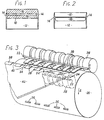
- Fig. 1 shows a plan view of a self-sealing envelope prior to folding of the flaps,
- Fig. 2 shows a similar view of the envelope with the flaps folded,
- Fig. 3 shows a simplified perspective view of part of the device of the present invention, and
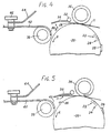
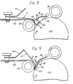
- Figs. 4 to 9 show diagrammatic side views of the device in successive stages of operation.
- Referring to the drawings, and firstly to Figs. 1 and 2; a conventional self-sealing envelope has a
front panel 10 andback panel 12 secured together byside flaps 14. Amain closure flap 16 is provided as an extension of the upper edge of thefront panel 10, and asecondary closure flap 18 is provided as an extension of the upper edge of theback panel 12. Prior to folding of the closure flaps, they are each coated on the same side with a self-sealing latex adhesive, as indicated by the hatching in Fig. 1. When the two closure flaps are folded downwardly as shown in Fig. 2, the adhesive layers lie face-to-face with portions of the envelope which do not carry adhesive. When it is desired to seal the envelope, both closure flaps are raised, and then themain closure flap 16 is folded over onto the raised secondary closure flap 18 so that the two adhesive surfaces come into contact and adhere together. The device of the present invention is concerned with folding the closure flaps from the position shown in Fig. 1 to the position shown in Fig. 2, and effecting this folding at high speed as part of an envelope making machine. - Referring to Fig. 3; this device comprises a
steel roller 20 which is driven so as to rotate in the direction of the arrow A. The roller is provided with internal ducting (not shown) for connection to a source of vacuum, the ducting being connected to openings on the surface of the roller. These openings are arranged as a leading band ofopenings 22 extending substantially continuously across the roller, and behind this leading band a series ofgroups 24 of openings spaced apart by unapertured regions. The total peripheral extent of the region having thesesuction openings main flap 16 of the envelope. In practice, a wider region of suction openings may be provided to allow for different sizes of envelopes, and any openings which are not desired for a particular size of envelope can be blanked off. Ahead of the leadingband 22 of openings, and spaced therefrom by the height of the front panel of the envelope, is a row offirst stop elements 26. These can be circumferentially adjustable to accommodate different sizes of envelopes. Behind the leadingband 22 of openings and alternating with thegroups 24 of openings the roller is provided with a row ofsecondary stop elements 28. Again, the circumferential setting of these stop elements can be adjusted. - A
bar 32 is closely spaced from the surface of the roller and extends parallel thereto. The bar carries a series oftongues 34 arranged so as to lie over the groups ofapertures 24 and between thesecond stop elements 28 as the roller rotates. Thebar 32 is pivotable to a small degree so that tongues can be raised and lowered as indicated by the double ended arrow B (see Fig. 4). A rubber surfacedroller 36 is located in contact with theroller 20 just before thebar 32. Shortly after the ends of thetongues 34 is located afurther roller 38 which is slightly spaced from the surface of theroller 20. Theroller 38 is provided with a series of circumferential grooves which freely receiveextension elements 40 at the edge of a table 42.Extension elements 40 are curved so as to follow the curvature of theroller 38 within the circumferential grooves (see Fig. 4). As can be seen also from Fig. 4, aplate 44 which extends towards theroller 36 is inclined upwardly at an acute angle with respect to the table 42. Theplate 44 is adjustably secured to the table by means of ascrew clamp 46. - In operation, the self-sealing envelopes are produced on a conventional machine, and adhesive is applied to the extended closure flaps to produce a succession of envelopes in the form shown in Fig. 1. These envelopes travel with their bottom edge leading, and are delivered towards the surface of the
roller 20 on the upstream side of the nip with theroller 36. The bottom edge of the envelope (designated 11 in Figs. 4 onwards) is arrested by engagement with thestop elements 26, and proceeds into the nip between therollers bar 32 and its associatedtongues 34, but, since there is nothing to hold it to the surface of the roller, the front panel of the envelope lifts from the surface of the roller after leaving the nip, as can be seen from Fig. 5. guided if necessary by thetongues 34 which are in the raised condition, the front edge of the envelope proceeds up over theroller 38 andextension elements 40 of the table 42, as can be seen in Fig. 6. At the same time, themain flap 16 of the envelope is passing through the nip and lies over thesuction apertures roller 20, Theflap 16 is therefore secured to the surface of the roller, and this provides transport for the envelope after leaving the nip. The continued travel of themain flap 16 with theroller 20 past the nip of theroller 36 causes the envelope to continue travelling over the table 42 in the direction indicated by the arrow C until the bottom edge of the envelope engages the abutment provided by theplate 44 as shown in Fig. 7. This arrests further movement of the envelope in that direction, and holds the main body of the envelope in approximately the same position relative to the surface of the roller, as can be seen in Fig. 7, while themain flap 16 continues to travel with the roller towards the gap between theroller 20 and theroller 38. In so doing, as can be seen from Fig. 8, theflap 16 starts to fold relative to the front panel of the envelope, the fold being properly formed by passage between therollers roller 20 starts to draw the main body of the envelope around theroller 38, and hence back in the direction indicated by the arrow D in Fig. 9. Initially, this causes the upper edge of thesecondary flap 18 to bear slidably upon the surface of theroller 20, and eventually brings the bottom edge of the envelope clear of theplate 44. Thetongues 34 are brought into their lowered positions as this happens. The upper edge of theflap 18 is engaged by thesecond stop elements 28, and thereby caused to move with the roller. The main body of the envelope, being free of theplate 44 then tends to assume a position generally radial with respect to theroller 20, as can be seen from Fig. 9. It will also be apparent that thesecondary closure flap 18 is at this point being folded with respect to the back panel of the envelope, and thetongues 34 prevent the flap folding in the wrong direction, particularly if the envelope tends to fill with air and billow out as it is brought backwards in the direction of arrow D. Continued movement of theroller 20 draws thesecondary closure flap 18 together with the main body of the envelope through the gap between therollers secondary flap 18 and back panel of the envelope. The envelope is now in the condition shown in Fig. 2, and can be delivered to a conventional envelope collating mechanism.
Claims (5)
Applications Claiming Priority (2)
| Application Number | Priority Date | Filing Date | Title |
|---|---|---|---|
| GB7827294 | 1978-06-19 | ||
| GB2729478 | 1978-06-19 |
Publications (2)
| Publication Number | Publication Date |
|---|---|
| EP0006342A1 EP0006342A1 (en) | 1980-01-09 |
| EP0006342B1 true EP0006342B1 (en) | 1982-05-05 |
Family
ID=10498034
Family Applications (1)
| Application Number | Title | Priority Date | Filing Date |
|---|---|---|---|
| EP79301115A Expired EP0006342B1 (en) | 1978-06-19 | 1979-06-12 | Device and method for folding self-sealing envelope flaps |
Country Status (5)
| Country | Link |
|---|---|
| US (1) | US4270909A (en) |
| EP (1) | EP0006342B1 (en) |
| DE (1) | DE2962687D1 (en) |
| DK (1) | DK248279A (en) |
| IL (1) | IL57537A0 (en) |
Families Citing this family (20)
| Publication number | Priority date | Publication date | Assignee | Title |
|---|---|---|---|---|
| JPS59158765A (en) * | 1983-02-28 | 1984-09-08 | Horizon:Kk | Paper folding device |
| DE3613117C2 (en) * | 1986-04-18 | 1995-12-14 | Winkler Duennebier Kg Masch | Folding device |
| FR2634729B1 (en) * | 1988-07-27 | 1990-09-14 | Alcatel Satman Sa | DEVICE FOR CLOSING ENVELOPES |
| DE4030414A1 (en) * | 1990-09-26 | 1992-04-02 | Winkler Duennebier Kg Masch | METHOD FOR PRODUCING SELF-ADHESIVE ENVELOPES |
| US6159330A (en) * | 1998-09-18 | 2000-12-12 | Moore U.S.A. Inc. | Pressure sealer serrated sealing roll |
| US6149752A (en) * | 1998-11-04 | 2000-11-21 | Privatizer Systems, Inc. | Apparatus and method for folding and sealing a mailer form having pressure sensitive adhesive positioned thereon |
| US6086698A (en) * | 1998-11-04 | 2000-07-11 | Privatizer Systems, Inc. | Apparatus and method for folding and sealing a mailer form having a roller with a deformable ring assembly secured thereto |
| US6156147A (en) * | 1998-11-04 | 2000-12-05 | Privatizer Systems, Inc. | Apparatus and method for biasing a first roller into operative contact with a second roller of a folder-sealer device |
| US6080251A (en) * | 1998-11-04 | 2000-06-27 | Privatizer Systems, Inc. | Folder-sealer device which is configured to receive mailer forms from a number of different paper sources |
| US6080259A (en) * | 1998-11-04 | 2000-06-27 | Privatizer Systems, Inc. | Method and apparatus for operating a folder-sealer device having a postage device associated therewith |
| US6162316A (en) * | 1998-11-04 | 2000-12-19 | Privatizer Systems, Inc. | Mailer form for use in a folder-sealer device |
| DE19901821A1 (en) * | 1999-01-19 | 2000-07-20 | Ficker Otto Ag | Envelope comprises a rear flap which is provided with a layer of adhesive agent and is pivotable into a closure position from its storage position on an envelope surface treated with a separation agent |
| US6193641B1 (en) * | 1999-04-14 | 2001-02-27 | Donald Barker | Apparatus for folding and sealing a sheet having pressure sensitive adhesive positioned thereon |
| DE10023712A1 (en) * | 2000-05-16 | 2001-11-22 | Winkler & Duennebier Ag | Device for folding folded products |
| US6790303B2 (en) * | 2001-12-17 | 2004-09-14 | Pitney Bowes Ltd. | Apparatus and method for sealing an envelope |
| US7146890B1 (en) * | 2005-05-13 | 2006-12-12 | Dennis Rowe | Annular octagonal hand held pushing tool for use with cutting and abrasive tools |
| JP6102101B2 (en) * | 2012-07-12 | 2017-03-29 | 富士ゼロックス株式会社 | Paper processing apparatus and image forming system |
| JP2014162577A (en) * | 2013-02-22 | 2014-09-08 | Riso Kagaku Corp | Sheet folding device |
| US9302444B1 (en) * | 2014-03-14 | 2016-04-05 | Chicago Tag & Label, Inc. | Label folding apparatus and methods for its use |
| US9409371B1 (en) | 2014-03-14 | 2016-08-09 | Chicago Tag & Label, Inc. | Label folding apparatus and methods for its use |
Family Cites Families (5)
| Publication number | Priority date | Publication date | Assignee | Title |
|---|---|---|---|---|
| US2019946A (en) * | 1934-03-28 | 1935-11-05 | Winkler Alfred | Process and apparatus for the manufacture of envelopes, bags, and similar articles |
| US2163038A (en) * | 1936-08-13 | 1939-06-20 | Us Envelope Co | Manufacture of dry-sealing envelopes |
| US3793926A (en) * | 1971-02-23 | 1974-02-26 | K Honsel | Apparatus for folding of envelope blanks |
| DE2142155C3 (en) * | 1971-08-23 | 1975-02-27 | Fa. Bruno Pahlitzsch, 1000 Berlin | Method and device for folding the closing flap and the counter flap on envelopes with self-adhesive gum |
| US3897720A (en) * | 1974-01-21 | 1975-08-05 | Tension Envelope Corp | Method of making envelope with insert |
-
1979
- 1979-06-11 IL IL57537A patent/IL57537A0/en unknown
- 1979-06-12 EP EP79301115A patent/EP0006342B1/en not_active Expired
- 1979-06-12 DE DE7979301115T patent/DE2962687D1/en not_active Expired
- 1979-06-12 US US06/047,806 patent/US4270909A/en not_active Expired - Lifetime
- 1979-06-14 DK DK248279A patent/DK248279A/en unknown
Also Published As
| Publication number | Publication date |
|---|---|
| DE2962687D1 (en) | 1982-06-24 |
| US4270909A (en) | 1981-06-02 |
| IL57537A0 (en) | 1979-10-31 |
| EP0006342A1 (en) | 1980-01-09 |
| DK248279A (en) | 1979-12-20 |
Similar Documents
| Publication | Publication Date | Title |
|---|---|---|
| US4270909A (en) | Device and method for folding self-sealing envelope flaps | |
| GB2023551A (en) | Folding Flaps | |
| US2851934A (en) | Manufacture of envelopes | |
| US2811905A (en) | Envelope manufacture | |
| US2772611A (en) | Envelope making method and mechanism | |
| US4862680A (en) | Bottom-folding packer | |
| US3628304A (en) | Method of forming envelopes having inserts therein from a moving blank web | |
| TW201636269A (en) | Method and device for correcting the folded position of a blank in a folder-gluer | |
| US2244723A (en) | Envelope machine | |
| US4179111A (en) | Folding mechanism | |
| US3354798A (en) | Method of making envelopes | |
| US3733982A (en) | Machine for producing self-opening envelopes | |
| US4003183A (en) | Method of enclosing insert material in a continuously advancing envelope blank | |
| US3599970A (en) | Apparatus for feeding blanks from the bottom of a stack | |
| US6811526B2 (en) | Folding-box gluing or adhesive-bonding machine with an ejector or removal device | |
| EP0138028B1 (en) | Slitter assembly for double fold bottomer apparatus | |
| US4173922A (en) | Method for making side seam envelopes from a web | |
| US3166996A (en) | Envelope making machine | |
| US2983201A (en) | Method of and apparatus for making envelopes | |
| US3264954A (en) | Method for manufacturing a taped box | |
| US4175476A (en) | Method and apparatus for forming reinforced top file folders | |
| US2846928A (en) | Method of making bags | |
| US3657975A (en) | Manufacture of bags which have a relatively wide base incorporating a filling valve | |
| US3367249A (en) | Method of making envelopes | |
| US2883917A (en) | Method and apparatus for folding trailing flaps |
Legal Events
| Date | Code | Title | Description |
|---|---|---|---|
| PUAI | Public reference made under article 153(3) epc to a published international application that has entered the european phase |
Free format text: ORIGINAL CODE: 0009012 |
|
| AK | Designated contracting states |
Designated state(s): BE DE FR IT NL SE |
|
| 17P | Request for examination filed | ||
| GRAA | (expected) grant |
Free format text: ORIGINAL CODE: 0009210 |
|
| AK | Designated contracting states |
Designated state(s): DE FR |
|
| REF | Corresponds to: |
Ref document number: 2962687 Country of ref document: DE Date of ref document: 19820624 |
|
| REG | Reference to a national code |
Ref country code: FR Ref legal event code: TP |
|
| PGFP | Annual fee paid to national office [announced via postgrant information from national office to epo] |
Ref country code: FR Payment date: 19900619 Year of fee payment: 12 |
|
| PGFP | Annual fee paid to national office [announced via postgrant information from national office to epo] |
Ref country code: DE Payment date: 19900622 Year of fee payment: 12 |
|
| PG25 | Lapsed in a contracting state [announced via postgrant information from national office to epo] |
Ref country code: FR Effective date: 19920228 |
|
| PG25 | Lapsed in a contracting state [announced via postgrant information from national office to epo] |
Ref country code: DE Effective date: 19920401 |
|
| REG | Reference to a national code |
Ref country code: FR Ref legal event code: ST |
|
| PLBE | No opposition filed within time limit |
Free format text: ORIGINAL CODE: 0009261 |
|
| STAA | Information on the status of an ep patent application or granted ep patent |
Free format text: STATUS: NO OPPOSITION FILED WITHIN TIME LIMIT |