EP0006331B1 - Inking system for pen recorders - Google Patents
Inking system for pen recorders Download PDFInfo
- Publication number
- EP0006331B1 EP0006331B1 EP79301085A EP79301085A EP0006331B1 EP 0006331 B1 EP0006331 B1 EP 0006331B1 EP 79301085 A EP79301085 A EP 79301085A EP 79301085 A EP79301085 A EP 79301085A EP 0006331 B1 EP0006331 B1 EP 0006331B1
- Authority
- EP
- European Patent Office
- Prior art keywords
- ink
- tubular member
- inking system
- recorder
- manifold
- Prior art date
- Legal status (The legal status is an assumption and is not a legal conclusion. Google has not performed a legal analysis and makes no representation as to the accuracy of the status listed.)
- Expired
Links
- 239000002904 solvent Substances 0.000 claims description 18
- 239000004800 polyvinyl chloride Substances 0.000 claims description 9
- 230000008020 evaporation Effects 0.000 claims description 8
- 238000001704 evaporation Methods 0.000 claims description 8
- 229920000915 polyvinyl chloride Polymers 0.000 claims description 8
- 230000037452 priming Effects 0.000 claims description 8
- 229920003023 plastic Polymers 0.000 claims description 4
- 239000004033 plastic Substances 0.000 claims description 4
- 239000000463 material Substances 0.000 claims description 3
- 239000004698 Polyethylene Substances 0.000 claims description 2
- -1 polyethylene Polymers 0.000 claims description 2
- 229920000573 polyethylene Polymers 0.000 claims description 2
- 230000004913 activation Effects 0.000 claims 1
- CURLTUGMZLYLDI-UHFFFAOYSA-N Carbon dioxide Chemical compound O=C=O CURLTUGMZLYLDI-UHFFFAOYSA-N 0.000 description 34
- 229910002092 carbon dioxide Inorganic materials 0.000 description 17
- 239000001569 carbon dioxide Substances 0.000 description 17
- 239000002184 metal Substances 0.000 description 6
- 230000000994 depressogenic effect Effects 0.000 description 5
- 239000007789 gas Substances 0.000 description 5
- 238000007789 sealing Methods 0.000 description 4
- XLYOFNOQVPJJNP-UHFFFAOYSA-N water Substances O XLYOFNOQVPJJNP-UHFFFAOYSA-N 0.000 description 4
- 239000002244 precipitate Substances 0.000 description 3
- JHIVVAPYMSGYDF-UHFFFAOYSA-N cyclohexanone Chemical compound O=C1CCCCC1 JHIVVAPYMSGYDF-UHFFFAOYSA-N 0.000 description 2
- 238000009792 diffusion process Methods 0.000 description 2
- 238000011010 flushing procedure Methods 0.000 description 2
- 239000003292 glue Substances 0.000 description 2
- 239000007788 liquid Substances 0.000 description 2
- XDTMQSROBMDMFD-UHFFFAOYSA-N Cyclohexane Chemical compound C1CCCCC1 XDTMQSROBMDMFD-UHFFFAOYSA-N 0.000 description 1
- 239000004677 Nylon Substances 0.000 description 1
- 229920001756 Polyvinyl chloride acetate Polymers 0.000 description 1
- DQXBYHZEEUGOBF-UHFFFAOYSA-N but-3-enoic acid;ethene Chemical compound C=C.OC(=O)CC=C DQXBYHZEEUGOBF-UHFFFAOYSA-N 0.000 description 1
- 238000000576 coating method Methods 0.000 description 1
- 238000010276 construction Methods 0.000 description 1
- 229920001577 copolymer Polymers 0.000 description 1
- 230000000881 depressing effect Effects 0.000 description 1
- 230000007613 environmental effect Effects 0.000 description 1
- 239000005038 ethylene vinyl acetate Substances 0.000 description 1
- 238000011049 filling Methods 0.000 description 1
- 150000008282 halocarbons Chemical class 0.000 description 1
- 229930195733 hydrocarbon Natural products 0.000 description 1
- 150000002430 hydrocarbons Chemical class 0.000 description 1
- 238000011068 loading method Methods 0.000 description 1
- 238000012986 modification Methods 0.000 description 1
- 230000004048 modification Effects 0.000 description 1
- 229920001778 nylon Polymers 0.000 description 1
- 238000009428 plumbing Methods 0.000 description 1
- 229920001200 poly(ethylene-vinyl acetate) Polymers 0.000 description 1
- 238000001556 precipitation Methods 0.000 description 1
- 238000009877 rendering Methods 0.000 description 1
- 230000004044 response Effects 0.000 description 1
- 230000000717 retained effect Effects 0.000 description 1
- 239000007787 solid Substances 0.000 description 1
Images
Classifications
-
- G—PHYSICS
- G01—MEASURING; TESTING
- G01D—MEASURING NOT SPECIALLY ADAPTED FOR A SPECIFIC VARIABLE; ARRANGEMENTS FOR MEASURING TWO OR MORE VARIABLES NOT COVERED IN A SINGLE OTHER SUBCLASS; TARIFF METERING APPARATUS; MEASURING OR TESTING NOT OTHERWISE PROVIDED FOR
- G01D15/00—Component parts of recorders for measuring arrangements not specially adapted for a specific variable
- G01D15/16—Recording elements transferring recording material, e.g. ink, to the recording surface
-
- G—PHYSICS
- G01—MEASURING; TESTING
- G01D—MEASURING NOT SPECIALLY ADAPTED FOR A SPECIFIC VARIABLE; ARRANGEMENTS FOR MEASURING TWO OR MORE VARIABLES NOT COVERED IN A SINGLE OTHER SUBCLASS; TARIFF METERING APPARATUS; MEASURING OR TESTING NOT OTHERWISE PROVIDED FOR
- G01D9/00—Recording measured values
- G01D9/28—Producing one or more recordings, each recording being of the values of two or more different variables
- G01D9/30—Producing one or more recordings, each recording being of the values of two or more different variables there being a separate recording element for each variable, e.g. multiple-pen recorder
Definitions
- the present invention relates to an inking system for pen recorders, and particularly to pen recorders in which the or each pen element is connected to a respective non-pressurized ink reservoir via a flexible tube.
- the tube is typically a small diameter plastics tube of 15-20 cm length.
- the common plastics materials are quite permeable to the solvents in the ink, which is in the form of dye in solution.
- a problem encountered with such recorders is that if the inking system is not used for some time, say a few weeks, the dye precipitates out and clogs the tube.
- US-A-3,136,597 shows a pen recorder in which the pen is connected to an ink reservoir via an ink supplying tube which consists of portions of normal diameter joined by a flexible intermediate portion of reduced wall thickness. Said intermediate portion is provided to reduce the mechanical loading on the pen element, and thus to enhance the mechanical response of the pen element to its driving signal.
- This prior art document is silent on the problem of clogging caused by ink lying in the ink supplying tube.
- US-A-3 589 402 discloses an inking system for a pen recorder in which the ink supply utilizes flexible tubing of polyvinylchloride.
- This specification teaches that polyvinylchloride is pervious to vapour which causes bubbles to be formed in the ink over a period of time, the bubbles causing the pen to skip.
- This prior specification proposes to overcome this problem by the use of two continuous coatings of finely divided solid resinous copolymer, i.e. suggests rendering the ink supplying tube impervious to gases.
- the invention overcomes the problem of ink clogging by providing in the ink supply a tubular member which has inside and outside diameters which are so related to the length thereof that, as evaporation of the solvent occurs, dye diffuses along the length of the flexible tubular member, toward the ink supply, substantially at a speed sufficient to prevent saturation from occurring in the ink within the flexible tubular member.
- the recorder pen may remain motionless for long periods of time without causing precipitation of the dye and clogging of either the ink supplying tube or the recorder pen.
- the ink priming system of the present invention is therein illustrated with one channel of the multi-pen recorder system being shown in detail.
- the capillary tube pen element 10 which comprises a metal tube having an extremely small diameter hole therethrough, is provided with a nib portion 12 which is adapted to engage the chart paper.
- the recording element 10 is mounted in a lightweight metal frame 14 which is secured to a suitable galvanometer type pen motor (not shown) so that the element 10 is rotated about the axis 15 in accordance with a given input signal, as will readily be understood by those skilled in the art.
- An ink bottle 16 is provided for each channel of the multi-pen recorder, and the ink 18 within the bottle 16 is normally supplied through the metal tube 20, which is mounted in the cap portion 22, a relatively large diameter thick-walled tubing section 24 and a relatively short, small diameter thin-walled tubing section 26 to the downwardly extending rear end portion 28 of the recording pen element 10.
- a pressurized ink priming system is provided for each of the channels of the multi-pen recorder. More particularly, a suitable gas, such as carbon dioxide, is stored in liquid form in a relatively large disposable bottle 32, the liquid carbon dioxide in the bottle 32 being at a relatively high pressure such as 5830 kN/m 2 (845 psig).
- a suitable gas such as carbon dioxide
- a bottle hold and puncturing device 34 is employed to hold the bottle 32 and supplies carbon dioxide through the tube 36, a manifold valve 38, and the tubing 40 to a pressure regulator 42 which reduces the pressure of carbon dioxide from the bottle 32 to a pressure above atmospheric in the range of from 27.6 to 69 kN/m 2 (4 to 10 psig). While other hydrocarbons or halocarbons are available with a lower vapor pressure, which will require a less rugged container 32 and a simpler pressure regulator 42 than when carbon dioxide is employed, carbon dioxide is preferred as a suitable gas from both a fire hazard and an environmental hazard standpoint.
- a spare carbon dioxide bottle 44 is mounted in the bottle holding and puncturing device 46 and may be selectively utilized in place of the bottle 32 by suitable actuation of the manifold valve 38.
- the output of the regulator 42 is supplied through a three-way valve 48 to a gas manifold 50 which is common to all of the recording channels of the multi-pen recorder. More particularly, the manifold 50 comprises a central chamber 52 which extends longitudinally along the length of the manifold 50 and is connected to the valve 48 through the conduit 54.
- a series of control valves indicated generally at 56 are mounted in the top wall of the manifold 50 and individually communicate with the chamber 52 through the vertical bores 58. Each of these control valves is actuated by means of a depressible top member 60.
- a flexible tube 62 is employed to interconnect a metal sleeve 64, which is mounted in the cap 60, and a metal sleeve 66, which is mounted in the ink bottle cap portion 22, the sleeve 66 communicating with the space 30 within the ink bottle 16 through the conduit 68 formed in the cap 22.
- the cap portion 22 is provided with an outwardly extending flange portion 70 which fits within and is engaged by the top wall of an outer cap member 72, a sealing washer 74 being provided on the flange 70 which seals the inner cap member 22 to the upper end of the screw thread portion of the ink bottle 16 so that a pressure seal is provided between the bottle 16 and the cap member 22.
- valve 56 this valve is of the so-called tank valve construction and is similar to a conventional automotive tire valve. More particularly, the valve 56 comprises an outer housing 76 the bottom end of which is threaded into the bore 58, the washer 78 and sealing ring 80 being provided to maintain a tight seal between the housing 76 and the manifold 50.
- a two-piece valve core 82 is threaded into the upper end of the housing 76 so that a tight seal is effected between the valve core seal 84 and the housing 76.
- a valve core pin 86 is slidably mounted in the valve core 82 and carries a valve seat seal 88 which is normally biased upwardly into engagement with the bottom end of the valve core 82 by means of the coil spring 90.
- the depressible cap member 60 is provided with a downwardly extending pin 92 in the top wall thereof so that when the cap 60 is depressed the valve core pin 86 is engaged and depressed and the control valve 56 is opened. As the cap 60 is depressed a sealing member 94 which is mounted in the cap 60 is moved downwardly into engagement with the upper end of the housing 76 to prevent gas supplied to the manifold 52 from escaping to the atmosphere. Accordingly, when the cap 60 is depressed the pressurized carbon dioxide in the manifold 52 is supplied through the valve 56 and the tubing 62 to the space 30 in the top of the ink bottle 1 6. As a result, the ink 18 is forced outwardly through the tubes 20, 24 and 26 and into the recording pen element 10 so that the recording pen tip 12 is primed.
- the cap 60 is depressed by the operator only for a sufficient time to establish the desired capillary ink flow between the bottle 16 and the pen tip 12 after which the cap 60 is released.
- the cap member 60 is positioned by means of the spring 90 with the sealing member 94 spaced above the upper end of the housing 76.
- the pressure established in the space 30 of the ink bottle 16 and the spring 90 cooperate to lift the cap 60 so that the pressurized carbon dioxide in the space 30 is bled off through the space between the outer threads 96 on the upper end of the housing 76 and the inner wall of the cap member 60.
- a threaded insert 98 is secured in the bottom end of the cap 60.
- the cap 60 is assembled on the upper end of the valve 56 by threading the insert 98 over the outer threaded portion 96 on the housing 76 so that the cap 60 is loosely retained on the upper end of the valve 56.
- the tubing 62 may then be connected to the corresponding ink bottle 16.
- control valves 56 are preferably of a tank valve type available from the Schrader Div. of Scovill Mfg. Co. which have a leakage rate of less than one nanoliter per second. Since the rest of the ink priming system is only pressurized intermittently, the corresponding seals do not have to have such a low leakage rate.
- the three-way valve 48 may be moved to the position in which the output of the regulator 42 is blocked so as to discontinue the supply of pressurized carbon dioxide to the manifold chamber 52. This minimizes the chance that one of the control valves 56 may accidently leak and vent all of the carbon dioxide in the bottle 32 to the atmosphere.
- the three-way valve 48 is turned to the position in which the output of the regulator 42 is supplied through the conduit 54 to the manifold chamber 52.
- the conduit 54 may be relatively long so that the carbon dioxide bottles 32, 44, pressure regulator 42, and valves 38, 48 may be positioned in a remote place while the manifold 50 is positioned relatively close to the row of ink bottles 16.
- the conduit 54 is made of nylon which is not permeable to carbon dioxide as other plastic materials.
- the manifold 50 is provided with one or two auxilary control valves 56a in addition to the control valves required for each of the ink bottles 16 associated with each recording pen of the multi-pen recorder.
- auxilary control valves 56a may be employed to flush out any one of the recording pens 10 or to blow ink out of the pens.
- the auxiliary control valve may be connected to a bottle 16 which is filled with a suitable solvent rather than the ink 18.
- the output tube 24a (FIG. 3), which is connected to the bottle of solvent, is then connected to an elbow block indicated generally at 100.
- the elbow. block 100 is provided with a vertically extending opening 102 in the top wall thereof into which the pen nib 12 may be tightly inserted.
- the opening 102 is connected to the end of the tube 24a through the conduit 104 and a metal tube 106 which extends out of the block 100.
- the auxiliary valve 56a When the auxiliary valve 56a is opened the solvent in the associated bottle 16 is forced through the tube 24a and the conduits 104 and 102 in the block 100 into the end of pen tip 12 so that solvent is fed in the reverse direction through the recording pen 10 and its associated tubing elements 26 and 24 so as to flush out these elements and remove any precipitated dye and/or the like which may remain therein.
- the ink bottle 16 is removed from the associated recording pen 10 when such a flushing operation is performed.
- the bottle associated with one of the auxiliary valves 56a may contain air, in which case ink may be blown from a selected one of the recording pens 10 by placing the pen tip 12 in the opening 102 and opening the corresponding auxiliary control valve 56a.
- the valve 56a When the valve 56a is opened carbon dioxide under pressure is forced into the bottle of air so that air under pressure is applied to the pen tip 12 and forces the ink in a reverse direction back through the recording pen 10 and the tubes 26 and 24.
- Such flushing or flowing of air into the recording pens may be utilized, for example, to prepare the recorder for storage, or the like.
- a hand pump indicated generally as 110 which may be used to pressurize the manifold chamber 52 during periods when no carbon dioxide bottle 32 is used. More particularly, the pump 110 comprises a rubber bulb 112 with check valves 114 and 118 at either end thereof.
- the check valve 114 is connected to one end of a long tube 11 6 the other end of which is connected to the three-way valve 48. In the third position of the valve 48 the tube 116 is connected to the tube 54 which communicates with the manifold chamber 52.
- the bulb 112 is squeezed air pressure up to approximately 69 kN/m 2 (10 psig) can be built up in the manifold chamber 52 and is prevented from escaping by means of the check valve 114.
- any one of the control valves 56 may be opened by depressing the cap 60 and air under pressure will be supplied to the space 30 above the ink reservoir 18 so that the corresponding pen 10 is primed in the manner described in detail here before.
- the hand pump 110 may be disconnected from the end of the tube 11 and the check valve 118 in the other end of the bulb 112 may be connected to the tube 116. If the tube 112 is then squeezed and released, a vacuum is established in the manifold chamber 52 as the squeezed bulb 112 expands. A vacuum of approximately -10.34 kN/m 2 (-1.5 psig) may be established with such an arrangement. After a vacuum of this level has been established in the manifold chamber 52, depression of any one of the cap members 60 causes the corresponding control valve 56 to open so that the vacuum in the manifold 52 may be used to draw ink out of the corresponding recorder pen 10 and into the ink bottle 16. Such an arrangement may be employed in place of the above described elbow block arrangement to remove ink from the recording pen 10.
- the tube 24 which is connected at its upper end to the right angle end portion 120 of the tube 20 has a relatively larger inner diameter and has relatively thick walls so that the solvent which is present in the ink 18 cannot readily evaporate through the walls of the tubing section 24.
- the tubing 24 is made of polyvinyl chloride or ethylene vinyl acetate, has an inside diameter of 1.57 mm (0.062 inches) and an outside diameter of 3.18 mm (0.125 inches) and may have an inner lining of polyethylene to reduce evaporation.
- the tubing section 26 is of relatively small inner diameter so it can fit over the capillary tube end portion 28 of the recorder pen 10 and is also flexible enough so it does not restrict movement of the recorder pen during a recording operation.
- the tubing section 26 is also made of polyvinyl chloride and has an inner diameter of 0.584 mm (.023 inches) and an outer diameter of 1.17 mm (.046 inches).
- the tubing section 26 is made relatively short and has a length such that evaporation of the ink solvent through the walls of the tubing section 26 is substantially balanced by diffusion of dye back into the adjacent end of the tubing section 24.
- the tubing 24 has a relatively large inner diameter and relatively little evaporation through the thick walls thereof so that the concentration of dye in the ink adjacent the tubing section 26 is substantially the same as in the bottle 16.
- the ink bottle is thus effectively connected to the end of the short tubing section 26, by employing the large diameter tubing 24, so that dye can diffuse out of the short length of tubing 26 and maintain the ink below saturation value throughout the length of the tubing 26.
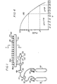
- rho(y) is plotted along the ordinate and y is plotted along the abscissa, where In this formula for y, X is the distance from the pen end of the tubing 26, and D is the diffusion constant for the particular dye molecules which are used in the ink.
- the quantity L/V for a particular tube can be measured by filling a given length of such tubing with water, plugging both ends and measuring the time required for all of the water to evaporate out of the tubing, i.e., the length of tubing divided by the velocity at which ink must enter the tubing to keep it full.
- the time required for all of the water to evaporate out of the tubing i.e., the length of tubing divided by the velocity at which ink must enter the tubing to keep it full.
- a period of from 15 to 20 days is required for all of the water to evaporate out of a length of tubing 20 cm long.
- the idealized characteristic 120 can be employed to determine the proper length of tubing 26 for a particular type of tubing and concentration of dye in the ink supply 18.
- the dye in the ink 18 within the bottle 16 has a concentration of 50% of its saturation blackness thus allowing for a substantial increase in concentration before reaching saturation. If the ink 18 has a higher concentration in the bottle 16 the trace is not any blacker but there is less change in concentration before saturation is reached. On the other hand, if a concentration less than 50% is used the trace will become progressively lighter as the concentration is reduced. From the characteristic 120 of FIG. 4 a concentration of .5 (50%) gives a value for "y" of 1.1774.
- the length of tubing 26 which is permitted under the ideal conditions of the characteristic 120 may then be calculated from the formula On the other hand, if the concentration of the dye in the bottle 26 is 20% (.2) then the length of tubing 26 may be substantially greater corresponding to a value of "y" in FIG. 4 of 1.8.
- the value L/V may be obtained, as discussed previously, by measuring the time required to evaporate all of the water out of a given length of tubing through the walls thereof. It should be emphasized that the characteristic 120 in FIG. 4 is based on the ideal situation in which there is equilibrium of the dye concentration distribution and corresponds to a condition in which the concentration of dye at the pen end of the tubing 26 never exceeds the saturation value of 1.0.
- the length of tubing 26 which is actually used may be somewhat longer than that indicated by the characteristic 120 and still provide non-clogging of the tubing 26 during periods of non-use of many months.
- the tubing 26 may have a length of 31.75 mm (1.25 inches).
- the end of the tube 26 is conveniently secured within the end of the larger tubing 24 by using a suitable glue, such as PVC dissolved in cyclohexanone or cyclohexane, or other suitable glue of the type used with PVC plumbing fixtures.
- a suitable glue such as PVC dissolved in cyclohexanone or cyclohexane, or other suitable glue of the type used with PVC plumbing fixtures.
- a preferred arrangement for supplying ink from the reservoir 18 to the capillary tube end portion 28 would be a conduit having a gradually tapered inner cross-section.
- a tapered pipe is quite difficult to fabricate on an economical basis.
- a tapered pipe may be approximated by employing several lengths of tubing having increasingly larger internal diameters so that a stepped conduit of increasingly larger inner diameter is provided in the direction away from the pen portion 28.
Landscapes
- Physics & Mathematics (AREA)
- General Physics & Mathematics (AREA)
- Pens And Brushes (AREA)
- Recording Measured Values (AREA)
Description
- The present invention relates to an inking system for pen recorders, and particularly to pen recorders in which the or each pen element is connected to a respective non-pressurized ink reservoir via a flexible tube.
- In recorders of this type, the tube is typically a small diameter plastics tube of 15-20 cm length. The common plastics materials are quite permeable to the solvents in the ink, which is in the form of dye in solution. A problem encountered with such recorders is that if the inking system is not used for some time, say a few weeks, the dye precipitates out and clogs the tube.
- Examples of various types of prior art inking systems for recorders are shown in the following documents: US-A-1,849,084; US-A-2,727,802; US-A-2,800,385; US-A-2,820,689; US-A-2,821,919; US-A-3,046,556; US-A-3,060,429; US-A-3,185,991; US-A-3,247,519; US-A-3,299,436; US-A-3,344,424; US-A-3,341,860; US-A-3,371,350; US-A-3,614,940; US-A-4,053,901; and U.S. Reissue Patent 25,692. The following patents are also cited as having general relevance to the present invention : US-A-626,750; US-A-1,907,763; US-A-2,769,573; US-A-3,208,639; and US-A-3,418,054.
- US-A-3,136,597 shows a pen recorder in which the pen is connected to an ink reservoir via an ink supplying tube which consists of portions of normal diameter joined by a flexible intermediate portion of reduced wall thickness. Said intermediate portion is provided to reduce the mechanical loading on the pen element, and thus to enhance the mechanical response of the pen element to its driving signal. This prior art document is silent on the problem of clogging caused by ink lying in the ink supplying tube.
- US-A-3 589 402 discloses an inking system for a pen recorder in which the ink supply utilizes flexible tubing of polyvinylchloride. This specification teaches that polyvinylchloride is pervious to vapour which causes bubbles to be formed in the ink over a period of time, the bubbles causing the pen to skip. This prior specification proposes to overcome this problem by the use of two continuous coatings of finely divided solid resinous copolymer, i.e. suggests rendering the ink supplying tube impervious to gases.
- The invention overcomes the problem of ink clogging by providing in the ink supply a tubular member which has inside and outside diameters which are so related to the length thereof that, as evaporation of the solvent occurs, dye diffuses along the length of the flexible tubular member, toward the ink supply, substantially at a speed sufficient to prevent saturation from occurring in the ink within the flexible tubular member.
- As a result, the recorder pen may remain motionless for long periods of time without causing precipitation of the dye and clogging of either the ink supplying tube or the recorder pen.
- These and other objects and advantages of the present invention will be better understood by reference to the following detailed description and attached drawing wherein:
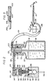
- FIG. 1 is a diagrammatic view of the inking system of the present invention;
- FIG. 2 is a sectional view taken along the line 2-2 of FIG. 1 and showing additionally the ink bottle and tubing connection to the recorder pen for one channel of the multi-channel recorder system;
- FIG. 3 is a sectional view of an attachment which can be used with the system of FIG. 1; and
- FIG. 4 is a graph which is useful in describing the non-clogging feature of the present invention.
- Referring now to the drawings, the ink priming system of the present invention is therein illustrated with one channel of the multi-pen recorder system being shown in detail. More particularly, the capillary
tube pen element 10, which comprises a metal tube having an extremely small diameter hole therethrough, is provided with anib portion 12 which is adapted to engage the chart paper. Therecording element 10 is mounted in alightweight metal frame 14 which is secured to a suitable galvanometer type pen motor (not shown) so that theelement 10 is rotated about theaxis 15 in accordance with a given input signal, as will readily be understood by those skilled in the art. Anink bottle 16 is provided for each channel of the multi-pen recorder, and theink 18 within thebottle 16 is normally supplied through themetal tube 20, which is mounted in thecap portion 22, a relatively large diameter thick-walled tubing section 24 and a relatively short, small diameter thin-walled tubing section 26 to the downwardly extendingrear end portion 28 of therecording pen element 10. - During normal operation of the recording channel, the
space 30 above theink 18 in thebottle 16 is not pressurized and hence the recording system acts as a conventional gravity- fed capillary type system. However, in accordance with the present invention, a pressurized ink priming system is provided for each of the channels of the multi-pen recorder. More particularly, a suitable gas, such as carbon dioxide, is stored in liquid form in a relatively large disposable bottle 32, the liquid carbon dioxide in the bottle 32 being at a relatively high pressure such as 5830 kN/m2 (845 psig). A bottle hold and puncturingdevice 34 is employed to hold the bottle 32 and supplies carbon dioxide through thetube 36, amanifold valve 38, and thetubing 40 to apressure regulator 42 which reduces the pressure of carbon dioxide from the bottle 32 to a pressure above atmospheric in the range of from 27.6 to 69 kN/m2 (4 to 10 psig). While other hydrocarbons or halocarbons are available with a lower vapor pressure, which will require a less rugged container 32 and asimpler pressure regulator 42 than when carbon dioxide is employed, carbon dioxide is preferred as a suitable gas from both a fire hazard and an environmental hazard standpoint. A sparecarbon dioxide bottle 44 is mounted in the bottle holding and puncturingdevice 46 and may be selectively utilized in place of the bottle 32 by suitable actuation of themanifold valve 38. - The output of the
regulator 42 is supplied through a three-way valve 48 to agas manifold 50 which is common to all of the recording channels of the multi-pen recorder. More particularly, themanifold 50 comprises acentral chamber 52 which extends longitudinally along the length of themanifold 50 and is connected to thevalve 48 through theconduit 54. A series of control valves indicated generally at 56 are mounted in the top wall of themanifold 50 and individually communicate with thechamber 52 through thevertical bores 58. Each of these control valves is actuated by means of a depressibletop member 60. Aflexible tube 62 is employed to interconnect ametal sleeve 64, which is mounted in thecap 60, and ametal sleeve 66, which is mounted in the inkbottle cap portion 22, thesleeve 66 communicating with thespace 30 within theink bottle 16 through theconduit 68 formed in thecap 22. Thecap portion 22 is provided with an outwardly extendingflange portion 70 which fits within and is engaged by the top wall of anouter cap member 72, asealing washer 74 being provided on theflange 70 which seals theinner cap member 22 to the upper end of the screw thread portion of theink bottle 16 so that a pressure seal is provided between thebottle 16 and thecap member 22. - Considering now in more detail the
control valve 56, this valve is of the so-called tank valve construction and is similar to a conventional automotive tire valve. More particularly, thevalve 56 comprises anouter housing 76 the bottom end of which is threaded into thebore 58, thewasher 78 and sealingring 80 being provided to maintain a tight seal between thehousing 76 and themanifold 50. A two-piece valve core 82 is threaded into the upper end of thehousing 76 so that a tight seal is effected between thevalve core seal 84 and thehousing 76. Avalve core pin 86 is slidably mounted in thevalve core 82 and carries avalve seat seal 88 which is normally biased upwardly into engagement with the bottom end of thevalve core 82 by means of thecoil spring 90. Thedepressible cap member 60 is provided with a downwardly extendingpin 92 in the top wall thereof so that when thecap 60 is depressed thevalve core pin 86 is engaged and depressed and thecontrol valve 56 is opened. As thecap 60 is depressed a sealingmember 94 which is mounted in thecap 60 is moved downwardly into engagement with the upper end of thehousing 76 to prevent gas supplied to themanifold 52 from escaping to the atmosphere. Accordingly, when thecap 60 is depressed the pressurized carbon dioxide in themanifold 52 is supplied through thevalve 56 and thetubing 62 to thespace 30 in the top of the ink bottle 1 6. As a result, theink 18 is forced outwardly through thetubes recording pen element 10 so that therecording pen tip 12 is primed. - The
cap 60 is depressed by the operator only for a sufficient time to establish the desired capillary ink flow between thebottle 16 and thepen tip 12 after which thecap 60 is released. Normally, thecap member 60 is positioned by means of thespring 90 with the sealingmember 94 spaced above the upper end of thehousing 76. When thecap 60 is released after an ink priming operation the pressure established in thespace 30 of theink bottle 16 and thespring 90 cooperate to lift thecap 60 so that the pressurized carbon dioxide in thespace 30 is bled off through the space between theouter threads 96 on the upper end of thehousing 76 and the inner wall of thecap member 60. - In order to retain the
cap 60 loosely on the upper end of thevalve 56, a threadedinsert 98 is secured in the bottom end of thecap 60. Initially, thecap 60 is assembled on the upper end of thevalve 56 by threading theinsert 98 over the outer threadedportion 96 on thehousing 76 so that thecap 60 is loosely retained on the upper end of thevalve 56. Thetubing 62 may then be connected to thecorresponding ink bottle 16. - In order to prevent the leakage of carbon dioxide from the
manifold 52 during periods when no recorder pen is being primed, thecontrol valves 56 are preferably of a tank valve type available from the Schrader Div. of Scovill Mfg. Co. which have a leakage rate of less than one nanoliter per second. Since the rest of the ink priming system is only pressurized intermittently, the corresponding seals do not have to have such a low leakage rate. - Considering now the operation of the ink priming system of the present invention, during periods when the ink priming system is not required, the three-
way valve 48 may be moved to the position in which the output of theregulator 42 is blocked so as to discontinue the supply of pressurized carbon dioxide to themanifold chamber 52. This minimizes the chance that one of thecontrol valves 56 may accidently leak and vent all of the carbon dioxide in the bottle 32 to the atmosphere. However, when the ink priming system is to be used, the three-way valve 48 is turned to the position in which the output of theregulator 42 is supplied through theconduit 54 to themanifold chamber 52. When the operator desires to prime a particular one of therecording pens 10, he depresses the corresponding one of thecap members 60 so that the associatedcontrol valve 56 is opened and carbon dioxide under pressure is supplied to theink bottle 16 and a flow of ink is established over the above described path to thepen tip 12. In this connection it will be understood that theconduit 54 may be relatively long so that thecarbon dioxide bottles 32, 44,pressure regulator 42, andvalves manifold 50 is positioned relatively close to the row ofink bottles 16. Preferably theconduit 54 is made of nylon which is not permeable to carbon dioxide as other plastic materials. In accordance with a further aspect of the invention, themanifold 50 is provided with one or twoauxilary control valves 56a in addition to the control valves required for each of theink bottles 16 associated with each recording pen of the multi-pen recorder. These auxiliary control valves may be employed to flush out any one of therecording pens 10 or to blow ink out of the pens. More particularly, the auxiliary control valve may be connected to abottle 16 which is filled with a suitable solvent rather than theink 18. Theoutput tube 24a (FIG. 3), which is connected to the bottle of solvent, is then connected to an elbow block indicated generally at 100. The elbow.block 100 is provided with a vertically extending opening 102 in the top wall thereof into which thepen nib 12 may be tightly inserted. The opening 102 is connected to the end of thetube 24a through theconduit 104 and ametal tube 106 which extends out of theblock 100. When theauxiliary valve 56a is opened the solvent in the associatedbottle 16 is forced through thetube 24a and theconduits block 100 into the end ofpen tip 12 so that solvent is fed in the reverse direction through therecording pen 10 and its associatedtubing elements ink bottle 16 is removed from the associatedrecording pen 10 when such a flushing operation is performed. In the alternative, the bottle associated with one of theauxiliary valves 56a may contain air, in which case ink may be blown from a selected one of the recording pens 10 by placing thepen tip 12 in theopening 102 and opening the correspondingauxiliary control valve 56a. When thevalve 56a is opened carbon dioxide under pressure is forced into the bottle of air so that air under pressure is applied to thepen tip 12 and forces the ink in a reverse direction back through therecording pen 10 and thetubes - In accordance with a further aspect of the invention, a hand pump indicated generally as 110 is provided which may be used to pressurize the
manifold chamber 52 during periods when no carbon dioxide bottle 32 is used. More particularly, thepump 110 comprises arubber bulb 112 withcheck valves check valve 114 is connected to one end of a long tube 11 6 the other end of which is connected to the three-way valve 48. In the third position of thevalve 48 thetube 116 is connected to thetube 54 which communicates with themanifold chamber 52. When thebulb 112 is squeezed air pressure up to approximately 69 kN/m2 (10 psig) can be built up in themanifold chamber 52 and is prevented from escaping by means of thecheck valve 114. After a suitable pressure has been established in themanifold chamber 52, any one of thecontrol valves 56 may be opened by depressing thecap 60 and air under pressure will be supplied to thespace 30 above theink reservoir 18 so that the correspondingpen 10 is primed in the manner described in detail here before. - In accordance with a futher aspect of the invention, the
hand pump 110 may be disconnected from the end of the tube 11 and thecheck valve 118 in the other end of thebulb 112 may be connected to thetube 116. If thetube 112 is then squeezed and released, a vacuum is established in themanifold chamber 52 as the squeezedbulb 112 expands. A vacuum of approximately -10.34 kN/m2 (-1.5 psig) may be established with such an arrangement. After a vacuum of this level has been established in themanifold chamber 52, depression of any one of thecap members 60 causes thecorresponding control valve 56 to open so that the vacuum in the manifold 52 may be used to draw ink out of the correspondingrecorder pen 10 and into theink bottle 16. Such an arrangement may be employed in place of the above described elbow block arrangement to remove ink from therecording pen 10. - In accordance with the invention, the
tube 24 which is connected at its upper end to the rightangle end portion 120 of thetube 20 has a relatively larger inner diameter and has relatively thick walls so that the solvent which is present in theink 18 cannot readily evaporate through the walls of thetubing section 24. Preferably thetubing 24 is made of polyvinyl chloride or ethylene vinyl acetate, has an inside diameter of 1.57 mm (0.062 inches) and an outside diameter of 3.18 mm (0.125 inches) and may have an inner lining of polyethylene to reduce evaporation. Thetubing section 26 is of relatively small inner diameter so it can fit over the capillarytube end portion 28 of therecorder pen 10 and is also flexible enough so it does not restrict movement of the recorder pen during a recording operation. Preferably, thetubing section 26 is also made of polyvinyl chloride and has an inner diameter of 0.584 mm (.023 inches) and an outer diameter of 1.17 mm (.046 inches). - In prior art arrangements a tube of the dimensions of the
tubing section 26 was connected all the way from theink bottle 16 to theend portion 28 of therecording pen 10, a distance in some instances of from 15 to 20 centimeters. Such a small diameter tubing was required in prior art arrangements when a rubber bulb was used on the ink bottle cap to prime the recording pens. We have found that when such a long length ofsmall tubing 26 is employed substantial evaporation of the ink solvent occurs through the relatively thin, permeable walls of the tubing when the recorder is not in use and thepen tip 12 is not moving. Since the evaporated solvent had to be replaced by drawing ink from the ink bottle, a relatively large ink current is established, which moves on the order of 10 mm per day, this ink current leaving the ink bottle and moving down the tubing to replace the evaporated solvent. When additional ink is thus drawn out of the ink bottle and into the small diameter tubing the concentration of dye in the tubing is increased and will reach saturation value, at which point the dye will precipitate out and clog the tubing unless some of the dye can diffuse back into the ink bottle. However, we have also found that the dye can diffuse out of such a small diameter tubing at only a rate of approximately 1 mm per day. This means that after a short period of non-use of the inking system the dye will exceed saturation value and will precipitate out and clog a length of tubing in the order of 15 to 20 cm. - In accordance with the present invention, the
tubing section 26 is made relatively short and has a length such that evaporation of the ink solvent through the walls of thetubing section 26 is substantially balanced by diffusion of dye back into the adjacent end of thetubing section 24. As stated heretofore, thetubing 24 has a relatively large inner diameter and relatively little evaporation through the thick walls thereof so that the concentration of dye in the ink adjacent thetubing section 26 is substantially the same as in thebottle 16. The ink bottle is thus effectively connected to the end of theshort tubing section 26, by employing thelarge diameter tubing 24, so that dye can diffuse out of the short length oftubing 26 and maintain the ink below saturation value throughout the length of thetubing 26. - Assuming that evaporation of the ink solvent is uniform along the length of the
tubing section 26, if the density of the dye divided by the saturation density is designated as "rho", the idealized characteristic 120 shown in FIG. 4 may be computed from the steady-state or equilibrium condition in which the dye concentration is at saturation at the end of thetube 26 adjacent therecording pen portion 28, i.e., rho (0) = 1.0 In Fig. 4 the value "rho(y)" is plotted along the ordinate and y is plotted along the abscissa, where
tubing 26, and D is the diffusion constant for the particular dye molecules which are used in the ink. The quantity L/V for a particular tube can be measured by filling a given length of such tubing with water, plugging both ends and measuring the time required for all of the water to evaporate out of the tubing, i.e., the length of tubing divided by the velocity at which ink must enter the tubing to keep it full. For example, with a polyvinyl chloride tubing of the dimensions given above for thetubing 26, a period of from 15 to 20 days is required for all of the water to evaporate out of a length oftubing 20 cm long. - The idealized characteristic 120 can be employed to determine the proper length of
tubing 26 for a particular type of tubing and concentration of dye in theink supply 18. Preferably, the dye in theink 18 within thebottle 16 has a concentration of 50% of its saturation blackness thus allowing for a substantial increase in concentration before reaching saturation. If theink 18 has a higher concentration in thebottle 16 the trace is not any blacker but there is less change in concentration before saturation is reached. On the other hand, if a concentration less than 50% is used the trace will become progressively lighter as the concentration is reduced. From the characteristic 120 of FIG. 4 a concentration of .5 (50%) gives a value for "y" of 1.1774. The length oftubing 26 which is permitted under the ideal conditions of the characteristic 120 may then be calculated from the formula
bottle 26 is 20% (.2) then the length oftubing 26 may be substantially greater corresponding to a value of "y" in FIG. 4 of 1.8. The value L/V may be obtained, as discussed previously, by measuring the time required to evaporate all of the water out of a given length of tubing through the walls thereof. It should be emphasized that the characteristic 120 in FIG. 4 is based on the ideal situation in which there is equilibrium of the dye concentration distribution and corresponds to a condition in which the concentration of dye at the pen end of thetubing 26 never exceeds the saturation value of 1.0. Since it is not necessary to design an inking system with such rigid requirements, the length oftubing 26 which is actually used may be somewhat longer than that indicated by the characteristic 120 and still provide non-clogging of thetubing 26 during periods of non-use of many months. For example, with apolyvinyl chloride tubing 26 of the dimensions given above, thetubing 26 may have a length of 31.75 mm (1.25 inches). - The end of the
tube 26 is conveniently secured within the end of thelarger tubing 24 by using a suitable glue, such as PVC dissolved in cyclohexanone or cyclohexane, or other suitable glue of the type used with PVC plumbing fixtures. In this connection it is pointed out that a preferred arrangement for supplying ink from thereservoir 18 to the capillarytube end portion 28 would be a conduit having a gradually tapered inner cross-section. However, such a tapered pipe is quite difficult to fabricate on an economical basis. In the alternative, a tapered pipe may be approximated by employing several lengths of tubing having increasingly larger internal diameters so that a stepped conduit of increasingly larger inner diameter is provided in the direction away from thepen portion 28. - While there have been described what are at present considered to be the preferred embodiments of the invention, it will be understood that various modifications may be made therein which are within the scope of the invention as defined in the claims.
Claims (11)
Applications Claiming Priority (2)
| Application Number | Priority Date | Filing Date | Title |
|---|---|---|---|
| US05/914,089 US4215352A (en) | 1978-06-09 | 1978-06-09 | Inking system with saturation control means for multi-pen recorders |
| US914089 | 1978-06-09 |
Publications (3)
| Publication Number | Publication Date |
|---|---|
| EP0006331A2 EP0006331A2 (en) | 1980-01-09 |
| EP0006331A3 EP0006331A3 (en) | 1980-08-06 |
| EP0006331B1 true EP0006331B1 (en) | 1984-01-04 |
Family
ID=25433902
Family Applications (1)
| Application Number | Title | Priority Date | Filing Date |
|---|---|---|---|
| EP79301085A Expired EP0006331B1 (en) | 1978-06-09 | 1979-06-07 | Inking system for pen recorders |
Country Status (5)
| Country | Link |
|---|---|
| US (1) | US4215352A (en) |
| EP (1) | EP0006331B1 (en) |
| JP (1) | JPS59617A (en) |
| DE (1) | DE2966520D1 (en) |
| DK (1) | DK239979A (en) |
Families Citing this family (7)
| Publication number | Priority date | Publication date | Assignee | Title |
|---|---|---|---|---|
| DE3024678C2 (en) * | 1980-06-30 | 1982-11-25 | Fa. J.S. Staedtler, 8500 Nürnberg | Device for feeding and controlling the writing medium for the writing unit of automatic writing or drawing machines |
| US5182572A (en) * | 1981-12-17 | 1993-01-26 | Dataproducts Corporation | Demand ink jet utilizing a phase change ink and method of operating |
| US4631557B1 (en) * | 1984-10-15 | 1997-12-16 | Data Products Corp | Ink jet employing phase change ink and method of operation |
| US4658274A (en) * | 1984-10-16 | 1987-04-14 | Exxon Printing Systems, Inc. | Melt ink jet apparatus with means and method for repriming |
| USD352875S (en) | 1993-06-01 | 1994-11-29 | Jetfill, Inc. | Cartridge pressurization tool |
| AU7502996A (en) * | 1995-11-08 | 1997-05-29 | American Ink Jet Corporation | Refilling ink jet cartridges |
| DE202022100433U1 (en) | 2022-01-25 | 2022-01-31 | Sayila Bala Gangadhara Tilak Babu | Smart pen that uses pressure sensors on the grip and machine learning to detect people's mental concentration |
Family Cites Families (12)
| Publication number | Priority date | Publication date | Assignee | Title |
|---|---|---|---|---|
| GB762846A (en) * | ||||
| GB707894A (en) * | 1951-03-12 | 1954-04-28 | Kelvin & Hughes Ltd | Improvements in or relating to pens for recorder instruments |
| US2800385A (en) * | 1953-01-23 | 1957-07-23 | Lloyd J Cannon | Ink feed apparatus |
| US3136597A (en) * | 1961-03-24 | 1964-06-09 | Westinghouse Electric Corp | Recording instrument |
| US3208639A (en) * | 1964-05-06 | 1965-09-28 | Finesse Products Inc | Sealed fluid dispensing system for oxidizable fluids |
| US3266048A (en) * | 1965-07-12 | 1966-08-09 | Clevite Corp | Recorder and inking system therefor |
| US3386102A (en) * | 1966-09-28 | 1968-05-28 | Victor Comptometer Corp | Ink supply system for recording apparatus |
| US3401401A (en) * | 1967-03-10 | 1968-09-10 | California Comp Products Inc | Multiple pen plotter cartridge |
| US3556477A (en) * | 1968-06-14 | 1971-01-19 | Clevite Corp | Ink flow control means for ink pen recorders |
| US3589402A (en) * | 1969-02-26 | 1971-06-29 | Westinghouse Electric Corp | Ink feed tubing |
| US4054883A (en) * | 1975-03-12 | 1977-10-18 | Kabushiki Kaisha Daini Seikosha | Ink pen device |
| US4038667A (en) * | 1976-04-28 | 1977-07-26 | Gould Inc. | Ink jet ink supply system |
-
1978
- 1978-06-09 US US05/914,089 patent/US4215352A/en not_active Expired - Lifetime
-
1979
- 1979-06-07 DE DE7979301085T patent/DE2966520D1/en not_active Expired
- 1979-06-07 EP EP79301085A patent/EP0006331B1/en not_active Expired
- 1979-06-08 DK DK239979A patent/DK239979A/en unknown
-
1983
- 1983-06-06 JP JP58099629A patent/JPS59617A/en active Pending
Also Published As
| Publication number | Publication date |
|---|---|
| DE2966520D1 (en) | 1984-02-09 |
| JPS59617A (en) | 1984-01-05 |
| EP0006331A2 (en) | 1980-01-09 |
| EP0006331A3 (en) | 1980-08-06 |
| DK239979A (en) | 1979-12-10 |
| US4215352A (en) | 1980-07-29 |
Similar Documents
| Publication | Publication Date | Title |
|---|---|---|
| US6854835B2 (en) | Ink cartridge for ink jet printer and method of charging ink into said cartridge | |
| US6612344B2 (en) | Integrated vent and fluid transfer fitment | |
| US4291317A (en) | Inking system for multi-pen recorders | |
| AU1519995A (en) | Thermoplastic closure for a fluid container and system for refilling a fluid reservoir | |
| US4045525A (en) | Gas humidification apparatus | |
| US4531660A (en) | Foam dispensing device | |
| CA2100664A1 (en) | A container for liquid anaesthetic agent | |
| EP0936073B1 (en) | Method of charging ink into an ink cartridge | |
| US4215352A (en) | Inking system with saturation control means for multi-pen recorders | |
| GB2154991A (en) | Liquid container tapping device | |
| GB2030962A (en) | Arrangement for metered dispensing of liquids and a methodof setting up such an arrangement | |
| US2938499A (en) | Combination pen and pressurized filling means | |
| US4974634A (en) | Liquid fertilizer metering system | |
| US2872951A (en) | Hydraulic brake system bleeding and refilling apparatus | |
| US5883652A (en) | Device for filling up a container with fluid | |
| US3985268A (en) | Non-drip dispenser | |
| US3059671A (en) | Device for replenishing fluid in a hydraulic system | |
| JPH0221959B2 (en) | ||
| FR2360479A1 (en) | Sterile plastics container esp. for blood plasma - has bacteria-proof vent and opening to seat needle (NL 7.2.78) | |
| ES2134908T3 (en) | DIFFUSER WITH FLANGE AND AIR CHAMBER RETAINER FOR PRESSURE CONTAINER. | |
| DK462587A (en) | VALVE FOR DELIVERY OF LIQUID FROM A CONTAINER. | |
| US4082163A (en) | Oil replenishing cartridge | |
| US2842291A (en) | Fluid handling means | |
| GB2202836A (en) | Dispensing container closure | |
| WO1987002346A1 (en) | Fluid dispensing apparatus |
Legal Events
| Date | Code | Title | Description |
|---|---|---|---|
| PUAI | Public reference made under article 153(3) epc to a published international application that has entered the european phase |
Free format text: ORIGINAL CODE: 0009012 |
|
| AK | Designated contracting states |
Designated state(s): CH DE FR GB IT SE |
|
| PUAL | Search report despatched |
Free format text: ORIGINAL CODE: 0009013 |
|
| AK | Designated contracting states |
Designated state(s): CH DE FR GB IT SE |
|
| 17P | Request for examination filed | ||
| 18D | Application deemed to be withdrawn |
Effective date: 19830119 |
|
| 18RR | Decision to grant the request for re-establishment of rights before grant |
Effective date: 19830609 |
|
| ITF | It: translation for a ep patent filed | ||
| D18D | Application deemed to be withdrawn (deleted) | ||
| GRAA | (expected) grant |
Free format text: ORIGINAL CODE: 0009210 |
|
| AK | Designated contracting states |
Designated state(s): CH DE FR GB IT SE |
|
| REF | Corresponds to: |
Ref document number: 2966520 Country of ref document: DE Date of ref document: 19840209 |
|
| PGFP | Annual fee paid to national office [announced via postgrant information from national office to epo] |
Ref country code: CH Payment date: 19840319 Year of fee payment: 6 |
|
| PGFP | Annual fee paid to national office [announced via postgrant information from national office to epo] |
Ref country code: FR Payment date: 19840321 Year of fee payment: 6 Ref country code: DE Payment date: 19840321 Year of fee payment: 6 |
|
| ET | Fr: translation filed | ||
| PGFP | Annual fee paid to national office [announced via postgrant information from national office to epo] |
Ref country code: SE Payment date: 19840331 Year of fee payment: 6 |
|
| PLBE | No opposition filed within time limit |
Free format text: ORIGINAL CODE: 0009261 |
|
| STAA | Information on the status of an ep patent application or granted ep patent |
Free format text: STATUS: NO OPPOSITION FILED WITHIN TIME LIMIT |
|
| 26N | No opposition filed | ||
| PG25 | Lapsed in a contracting state [announced via postgrant information from national office to epo] |
Ref country code: SE Effective date: 19860608 |
|
| PG25 | Lapsed in a contracting state [announced via postgrant information from national office to epo] |
Ref country code: CH Effective date: 19860630 |
|
| PG25 | Lapsed in a contracting state [announced via postgrant information from national office to epo] |
Ref country code: FR Free format text: LAPSE BECAUSE OF NON-PAYMENT OF DUE FEES Effective date: 19870227 |
|
| REG | Reference to a national code |
Ref country code: CH Ref legal event code: PL |
|
| PG25 | Lapsed in a contracting state [announced via postgrant information from national office to epo] |
Ref country code: DE Effective date: 19870303 |
|
| GBPC | Gb: european patent ceased through non-payment of renewal fee | ||
| REG | Reference to a national code |
Ref country code: FR Ref legal event code: ST |
|
| PG25 | Lapsed in a contracting state [announced via postgrant information from national office to epo] |
Ref country code: GB Effective date: 19881118 |
|
| EUG | Se: european patent has lapsed |
Ref document number: 79301085.1 Effective date: 19870504 |