EP0005681B1 - Tube support grid and method of making - Google Patents
Tube support grid and method of making Download PDFInfo
- Publication number
- EP0005681B1 EP0005681B1 EP79810037A EP79810037A EP0005681B1 EP 0005681 B1 EP0005681 B1 EP 0005681B1 EP 79810037 A EP79810037 A EP 79810037A EP 79810037 A EP79810037 A EP 79810037A EP 0005681 B1 EP0005681 B1 EP 0005681B1
- Authority
- EP
- European Patent Office
- Prior art keywords
- ring
- frame
- external
- annular
- cylindrical surface
- Prior art date
- Legal status (The legal status is an assumption and is not a legal conclusion. Google has not performed a legal analysis and makes no representation as to the accuracy of the status listed.)
- Expired
Links
- 238000004519 manufacturing process Methods 0.000 title claims description 5
- 125000006850 spacer group Chemical group 0.000 claims description 62
- 241000282472 Canis lupus familiaris Species 0.000 claims description 29
- 239000000463 material Substances 0.000 claims description 15
- 230000002093 peripheral effect Effects 0.000 claims description 12
- 238000004140 cleaning Methods 0.000 claims description 6
- 230000013011 mating Effects 0.000 claims description 2
- 230000000903 blocking effect Effects 0.000 claims 1
- 230000000149 penetrating effect Effects 0.000 claims 1
- 239000010935 stainless steel Substances 0.000 description 24
- 229910001220 stainless steel Inorganic materials 0.000 description 24
- 229910000975 Carbon steel Inorganic materials 0.000 description 11
- 239000010962 carbon steel Substances 0.000 description 11
- XLYOFNOQVPJJNP-UHFFFAOYSA-N water Substances O XLYOFNOQVPJJNP-UHFFFAOYSA-N 0.000 description 8
- 239000003292 glue Substances 0.000 description 6
- 238000005304 joining Methods 0.000 description 6
- 230000007797 corrosion Effects 0.000 description 4
- 238000005260 corrosion Methods 0.000 description 4
- 239000002184 metal Substances 0.000 description 3
- 239000000853 adhesive Substances 0.000 description 2
- 230000001070 adhesive effect Effects 0.000 description 2
- 230000015572 biosynthetic process Effects 0.000 description 2
- 239000012530 fluid Substances 0.000 description 2
- 238000003466 welding Methods 0.000 description 2
- 230000009471 action Effects 0.000 description 1
- 238000009835 boiling Methods 0.000 description 1
- 210000001520 comb Anatomy 0.000 description 1
- 238000010276 construction Methods 0.000 description 1
- 230000008878 coupling Effects 0.000 description 1
- 238000010168 coupling process Methods 0.000 description 1
- 238000005859 coupling reaction Methods 0.000 description 1
- 230000000694 effects Effects 0.000 description 1
- 230000008030 elimination Effects 0.000 description 1
- 238000003379 elimination reaction Methods 0.000 description 1
- 230000005284 excitation Effects 0.000 description 1
- 230000001771 impaired effect Effects 0.000 description 1
- SZVJSHCCFOBDDC-UHFFFAOYSA-N iron(II,III) oxide Inorganic materials O=[Fe]O[Fe]O[Fe]=O SZVJSHCCFOBDDC-UHFFFAOYSA-N 0.000 description 1
- 238000003754 machining Methods 0.000 description 1
- 239000000155 melt Substances 0.000 description 1
- 230000000379 polymerizing effect Effects 0.000 description 1
- 230000009467 reduction Effects 0.000 description 1
- 230000000717 retained effect Effects 0.000 description 1
- 229920006395 saturated elastomer Polymers 0.000 description 1
- 239000002904 solvent Substances 0.000 description 1
- 239000000126 substance Substances 0.000 description 1
Images




Classifications
-
- F—MECHANICAL ENGINEERING; LIGHTING; HEATING; WEAPONS; BLASTING
- F28—HEAT EXCHANGE IN GENERAL
- F28F—DETAILS OF HEAT-EXCHANGE AND HEAT-TRANSFER APPARATUS, OF GENERAL APPLICATION
- F28F9/00—Casings; Header boxes; Auxiliary supports for elements; Auxiliary members within casings
- F28F9/007—Auxiliary supports for elements
- F28F9/013—Auxiliary supports for elements for tubes or tube-assemblies
- F28F9/0135—Auxiliary supports for elements for tubes or tube-assemblies formed by grids having only one tube per closed grid opening
- F28F9/0136—Auxiliary supports for elements for tubes or tube-assemblies formed by grids having only one tube per closed grid opening formed by intersecting strips
-
- Y—GENERAL TAGGING OF NEW TECHNOLOGICAL DEVELOPMENTS; GENERAL TAGGING OF CROSS-SECTIONAL TECHNOLOGIES SPANNING OVER SEVERAL SECTIONS OF THE IPC; TECHNICAL SUBJECTS COVERED BY FORMER USPC CROSS-REFERENCE ART COLLECTIONS [XRACs] AND DIGESTS
- Y10—TECHNICAL SUBJECTS COVERED BY FORMER USPC
- Y10S—TECHNICAL SUBJECTS COVERED BY FORMER USPC CROSS-REFERENCE ART COLLECTIONS [XRACs] AND DIGESTS
- Y10S165/00—Heat exchange
- Y10S165/355—Heat exchange having separate flow passage for two distinct fluids
- Y10S165/40—Shell enclosed conduit assembly
- Y10S165/401—Shell enclosed conduit assembly including tube support or shell-side flow director
- Y10S165/405—Extending in a longitudinal direction
- Y10S165/407—Extending in a longitudinal direction internal casing or tube sleeve
- Y10S165/409—Extending in a longitudinal direction internal casing or tube sleeve including transverse element, e.g. fin, baffle
- Y10S165/41—Movable internal casing connecting to transverse element
Definitions
- This invention relates to a grid for supporting tubes in steam generators, heat exchangers and the like.
- conventional apparatus such as steam generators for use, for example, in a P.W.R. reactor system
- conventional tubes plates, welded tube grid supports and more recent tube grid supports with mechanical fitting joints are used to receive the tubes or pipes and to support them during the assembling of the tube bundle in said steam generator and during the operating time.
- a grid support has been described in DE-A-2.541.986.
- This grid consists of a peripheral frame which receives a reticular structure formed of lower and upper set of equally spaced main intersecting strips having interengaging main milled slots at the intersecting zones and equally spaced secondary milled slots therebetween and a lower and an upper set of equally spaced secondary strips located in said secondary milled slots.
- the frame holds the reticular structure by means of lower and upper dogs which penetrate in grooves provided in the strip ends.
- the present invention is directed to a solution of such problems and has as a general objective the provision of a novel tube grid support, wherein the supported tubes, the support grid and particularly the mechanical fitting joints between the strip ends and the peripheral frame structure have increased rigidity and are not subjected to chemical, mechanical and/or thermic stresses during the assembling and/or the operating time.
- a further object of the present invention is to provide a tube grid support, which is economical to manufacture, rigid in construction, rigid during the assembling in the apparatus, during the transportation and erection of the apparatus at the site, elastic in operation and reliable for long operating time.
- the present invention provides a new support grid for tubes in two different materials, comprising a central reticular structure, formed for example of stainless steel strips, and a peripheral inner annular frame, formed in the same material as the reticular structure, for example stainless steel, containing the strip ends and being higher than said reticular structure, so as two projecting portions are formed; and an external annular frame formed in a different material and consisting of an external box ring and of a cover ring capable of receiving and containing therein said projecting portions of the inner frame, axially extended and inwardly facing dogs being provided at the inner portion of said external frame; the inner frame and the external frame being assembled so that at room temperature said dogs of the external frame fit into the inner cylindrical surface of said projecting portions while play exists between the external cylindrical surface of the inner frame and the internal cylindrical surface of the external frame.
- the support grid structure produced in accordance with the invention is particularly suitable for supporting the tubes in apparatus such as steam generators, for example nuclear steam generators of P.W.R. Reactors, heat exchangers and the like.
- the central reticular structure is formed of a lower and an upper set of main and secondary strips, equally spaced, intersecting each other by means of milled slots in the main strips, the strips fitting together in the manner of combs.
- the inner annular frame is formed in a single piece provided with milled slots so as to receive the strip ends or it may comprise an independent intermediate frame ring, thereto being rigidly connected, by means of pins and/or by welds, a lower and an upper set of block-like spacers forming slots between one another so as to receive the ends of said lower and upper strips respectively, said intermediate annular frame ring being fitted to the lower and upper main strip ends.
- the external annular frame is formed of a lower L-shaped box frame ring and an upper L-shaped cover frame ring rigidly fixed together and having internal annular dogs axially extending, inwardly facing and overlapping an external annular portion of the reticular structure, said annular dogs fitting, in the manner of a free thermal expansion joint, the conjugate internal cylindrical surfaces of the peripheral inner frame, said cylindrical surfaces projecting on both sides, with respect to the upper and lower surfaces of the reticular structure.
- the type of grid in accordance with the invention has the following advantages as compared to the conventional welded joints or to more recent conventional mechanical joints produced with fitting grooves into the ends of the strips:
- the strip ends have in every point of the contacting area with the adjacent spacers the full cross section corresponding to the total height of the strip end.
- strip ends are not subjected to the forces produced by the fluid circulation or by boiling.
- the radial forces in the supporting grid due to the transverse hydraulic excitation of the tubes caused by the cross-flow of the feed water or of the recirculated water will be transmitted by the reticular structure directly to the inner annular frame.
- strip ends and the contacted adjacent spacers are both of the same material, for example of stainless steel.
- the external generally cylindrical surfaces 1-s, 2-s, 3-s, 4-s, 5-s, of the strip ends 1, 2, 3, 4 and independent intermediate frame ring 5 respectively are generally aligned to each other both at room and operating temperatures, that is all said surfaces are always positioned on a unique envelopping cylindrical surface.
- the milled slots of the main strips are equally mutually spaced and are of two kinds:
- a normal grid of this type comprises, for example, two dozen main or carrying strips and eight secondary strips for each main strip, the finished grid having a diameter of about 3m.
- the lower main strips 1 are first placed on the assembly template 20; at the bottom such strips terminate with an L end 1-o covering piece 6-m at the conjugate surface 6-o thereof.
- piece 5 in stainless steel is assembled, piece 5 being a continuous ring rigidly joined to the main spacers 6-m and 7-m (by means like through pins 13 and/or by welds 14), whereupon and between the adjacent main spacers 7-m the upper main strips 2 are assembled, these strips also having an L-end 2-o downwards facing. That is the end thereof is such to cover piece 7-m, at the conjugate surface thereof 7-o.
- a lower secondary spacer block 6 is inserted; in the axial extending blind hole 6-z thereof has been previously assembled a spring 11 and thereupon a pin 10, so that the spacer 6 is fixed by pushing out of the pin 10 in the groove 5-v of the ring 5 under the action of said spring 11, when said spacer 6 has been pushed in its definitive position under the ring 5 and stopped by the auxiliary assembly ring segment 21.
- an upper secondary spacer block 7 is now inserted and stopped by the auxiliary assembly ring segment 22, thereafter the pin 12 is inserted in the axial extending through hole 7-z of the spacer 7 and in the groove 5-x of the frame ring 5.
- auxiliary assembly ring segments 21 and 22 are successively dismounted and the external frame rings 8 and 9, the surfaces 8-i and 9-i thereof and/or the conjugate surfaces 6-i and 7-i respectively being previously covered with a layer of said metal paste or glue, are at last assembled and interconnected by means of welded bolts or pins 15.
- the flow of water and saturated steam melts the glue or paste and the strips and the intermediate framework are free to expand, that is strips 1, 2, 3 and 4 of stainless steel, the independent frame ring 5 interengaged with spacers 6, 6-m and 7, 7-m also in stainless steel slide together at substantially same rate with little or no relative thermal expansion, the required clearances being provided.
- the said last mentioned parts assume the position 5', 6-m', 7-m' as shown in the drawing Figure 6.
- the external frame components that is pieces 8, 9, which are of carbon steel, may expand freely to a lesser extent.
- the mutual position of the lower and upper dogs 8-a and 9-a of the box frame ring and cover frame ring respectively with the conjugate lower and upper spacer surfaces 6-t and 7-t respectively is such that at room temperature the outer surfaces 8-t and 9-t of the dogs 8-a and 9-a respectively contact rigidly the inner conjugate surfaces 6-t and 7-t of the spacers, as shown in the drawing, while at operating temperature, for example 300°C, between said outer cylindrical surfaces 8-t and 9-t of the dogs 8-a and 9-a respectively and the inner conjugate cylindrical surfaces 6-t and 7-t of the lower and upper spacers respectively is sufficient play 18 to allow flow of the hot water 19 through the lower and upper set of the radial cleaning ducts 6-e and 7-e respectively, between the adjacent spacers, overlying the strip ends, and through the axial extending interspaced holes 8-e, 9-e, formed through the external frame ring annular region facing the play 17 between said external frame rings and the inner frame.
- the glue layer 32 applied on the external surface of the wedges 30 inserted about the grid will unglue and leave a free clearance equal to the thickness of the previously inserted glue or paste.
- This enables a free axial sliding between the pack of grids maintained spaced apart from one another by spacers 33 made of stainless steel and the casing 31 of carbon steel.
- said dogs 8-a and 9-a on the external frame serve also the purpose of retaining the spacers, when unglued, during operation, in the case of breakage of the interconnecting pins 10 and 12.
- the unique difference to be noted in the above mentioned drawings is the different embodiment of the inner frame, that consists of a single intermediate spacer ring 45 in stainless steel having a height equal to the sum of the partial height of lower spacer 6 or 6-m, intermediate spacer ring 5 and upper spacer 7 or 7-m represented in the Figure 1-10, said single ring 45 having a set of lower milled teeth 45-o generally radially extending and a set of upper milled teeth 45-o' also generally radially extending, both sets of teeth provided to receive in the space-like slot (45r; 45v) between adjacent teeth the ends 1-o, 3-o and 2-o, 4-o of the lower and upper strips respectively.
- the material described above for the preferred and the alternative embodiment of the grid support may also be substituted by equivalent material and for each pair of said different materials for the circular grid structure and for the outer box frame there will be suitable play therebetween to allow free differential thermal expansion in the area of the joint.
- a template for the final assembling of the finished component parts of the supporting grid is comprising:
Landscapes
- Engineering & Computer Science (AREA)
- Physics & Mathematics (AREA)
- Thermal Sciences (AREA)
- Mechanical Engineering (AREA)
- General Engineering & Computer Science (AREA)
- Heat-Exchange Devices With Radiators And Conduit Assemblies (AREA)
- Structure Of Emergency Protection For Nuclear Reactors (AREA)
- Monitoring And Testing Of Nuclear Reactors (AREA)
Description
- This invention relates to a grid for supporting tubes in steam generators, heat exchangers and the like. In conventional apparatus, such as steam generators for use, for example, in a P.W.R. reactor system, conventional tubes plates, welded tube grid supports and more recent tube grid supports with mechanical fitting joints (produced with grooves in the strip ends) are used to receive the tubes or pipes and to support them during the assembling of the tube bundle in said steam generator and during the operating time.
- A grid support has been described in DE-A-2.541.986. This grid consists of a peripheral frame which receives a reticular structure formed of lower and upper set of equally spaced main intersecting strips having interengaging main milled slots at the intersecting zones and equally spaced secondary milled slots therebetween and a lower and an upper set of equally spaced secondary strips located in said secondary milled slots. The frame holds the reticular structure by means of lower and upper dogs which penetrate in grooves provided in the strip ends.
- This solution creates in the strip ends zones of possible failure. Moreover pockets are created between strips and frame where corrosion products may be retained, so that the life of the tubes and of the support is impaired.
- The present invention is directed to a solution of such problems and has as a general objective the provision of a novel tube grid support, wherein the supported tubes, the support grid and particularly the mechanical fitting joints between the strip ends and the peripheral frame structure have increased rigidity and are not subjected to chemical, mechanical and/or thermic stresses during the assembling and/or the operating time. A further object of the present invention is to provide a tube grid support, which is economical to manufacture, rigid in construction, rigid during the assembling in the apparatus, during the transportation and erection of the apparatus at the site, elastic in operation and reliable for long operating time.
- The present invention provides a new support grid for tubes in two different materials, comprising a central reticular structure, formed for example of stainless steel strips, and a peripheral inner annular frame, formed in the same material as the reticular structure, for example stainless steel, containing the strip ends and being higher than said reticular structure, so as two projecting portions are formed; and an external annular frame formed in a different material and consisting of an external box ring and of a cover ring capable of receiving and containing therein said projecting portions of the inner frame, axially extended and inwardly facing dogs being provided at the inner portion of said external frame; the inner frame and the external frame being assembled so that at room temperature said dogs of the external frame fit into the inner cylindrical surface of said projecting portions while play exists between the external cylindrical surface of the inner frame and the internal cylindrical surface of the external frame.
- The support grid structure produced in accordance with the invention is particularly suitable for supporting the tubes in apparatus such as steam generators, for example nuclear steam generators of P.W.R. Reactors, heat exchangers and the like.
- Between the reticular structure and the peripheral inner annular frame is provided a mechanical fit, while between the peripheral inner annular frame containing the strip ends and the external frame structure is provided a sliding mechanical fit, with play for free differential thermal expansion between the two different materials.
- The central reticular structure is formed of a lower and an upper set of main and secondary strips, equally spaced, intersecting each other by means of milled slots in the main strips, the strips fitting together in the manner of combs.
- The inner annular frame is formed in a single piece provided with milled slots so as to receive the strip ends or it may comprise an independent intermediate frame ring, thereto being rigidly connected, by means of pins and/or by welds, a lower and an upper set of block-like spacers forming slots between one another so as to receive the ends of said lower and upper strips respectively, said intermediate annular frame ring being fitted to the lower and upper main strip ends.
- The external annular frame is formed of a lower L-shaped box frame ring and an upper L-shaped cover frame ring rigidly fixed together and having internal annular dogs axially extending, inwardly facing and overlapping an external annular portion of the reticular structure, said annular dogs fitting, in the manner of a free thermal expansion joint, the conjugate internal cylindrical surfaces of the peripheral inner frame, said cylindrical surfaces projecting on both sides, with respect to the upper and lower surfaces of the reticular structure.
- With reference particularly to the use of the supporting grid for tubes in the nuclear steam generators of P.W.R. reactors, wherein flow velocities, temperatures and fluid pressures are all of a high order, the type of grid in accordance with the invention has the following advantages as compared to the conventional welded joints or to more recent conventional mechanical joints produced with fitting grooves into the ends of the strips:
- a) increased mechanical strength of the joint, high reliability and consequent long duration of the same.
- In fact the strip ends have in every point of the contacting area with the adjacent spacers the full cross section corresponding to the total height of the strip end.
- Moreover the strip ends are not subjected to the forces produced by the fluid circulation or by boiling. In fact, the radial forces in the supporting grid due to the transverse hydraulic excitation of the tubes caused by the cross-flow of the feed water or of the recirculated water will be transmitted by the reticular structure directly to the inner annular frame.
- Also the axial forces on the supporting grid due to the flow of the feed water or of the recirculated water parallel to and along the supported tubes and therefore perpendicular to the plane of the supporting grid will be transmitted directly from the reticular structure to the internal annular dogs of the external frame rings of the support.
- b) Absence or considerable reduction of the formation of build-up corrosion products in the contact zone between the two materials during the operating time. The new design concept of the new joint, that is the proper selection of the materials and the proper geometry of the joint, minimizes considerably the potential for the concentration of corrosion products in that area. This could prevent the free expansion of the circular grid structure and could damage the joint.
- In fact the strip ends and the contacted adjacent spacers are both of the same material, for example of stainless steel.
- Moreover there is no relative movement and therefore no fretting between the ends of the main supporting strips of the reticular grid structure and the adjacent spacers, fixed rigidly to the independent intermediate frame ring since said ring, said spacers and said main strip being fitted one in the other and having a substantially equal thermic expansion coefficient, will expand and contract together at the same rate under varying temperature.
- If fretting between the above mentioned spacers in stainless steel and the facing overlying flange rings of the external framework in carbon steel will cause the formation of some magnetite corrosion products these will be removed, as hereinafter described, by forcing water through the numerous axial interspaced cleaning holes provided in the upper and lower parts of the external frame, through the substantial play provided between the stainless steel inner frame and the carbon steel external frame and through the cleaning ducts provided in the projecting portions of the inner frame.
- c) Precision in achieving a more correct geometry of the circular grid structure, that is centered without play on the external box shaped annular frame during the assembly operation, only mechanical and very few not deforming welding operations being involved during the manufacture.
- d) Assembly of the complete supporting grid at one time, that is no moving of the circular grid structure, in partial assembled condition, for a subsequent machining and after again moving for the final assembly.
- All component parts are prepared and arranged properly on a template before the final assembly at one time, thus reducing considerably the total time and therefore the total cost for the manufacture and assembling of the complete supporting grid.
- e) More precision in the alignment of several support grids of the type described having the same geometrical configuration and a more rigid structure particularly in the external frame in carbon steel.
- f) More facility and speed in inserting the pipes in the tube places.
- g) Elimination of damage to the tubes during the inserting operation and/or during operation, caused by fretting and/or denting between the tubes and the supports in carbon steel and/or of less precision such as those of tube plate type or of grid type having welded joints or mechanical joints produced with fitting grooves in the strip ends.
- The objects and the advantages of the present invention will become apparent as the description proceeds with the aid of the accompanying drawings, which show a typical but not limiting solution of a preferred embodiment and of an alternate embodiment of the supporting grid.
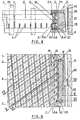
- Figure 1 represents schematically the support grid in a plan view.
- Figure 2 represents in a larger scale a portion of the preferred embodiment of the circular grid structure of the support in a perspective view.
- Figure 3 represents in a larger scale a portion of the preferred embodiment of the support in a partial plan view.
- Figure 4 represents in a larger scale a portion of the preferred embodiment of the support in cross-section along the line IV-IV of the plan view of Figure 3.
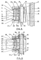
- Figure 5 represents in a larger scale a portion of the preferred embodiment of the support in cross-section along the line V-V of the plan view of Figure 3 (when the support is at room temperature).
- Figure 5a represents in a larger scale a portion of an alternative embodiment of the support in a modified cross-section along the line V-V of the plan view of Figure 3 (support at room temperature).
- Figure 6 represents in a larger scale a portion of the preferred embodiment of the support in cross-section along the line VI-VI of the plan view of Figure 3 (when the supports is at operating temperature, for example at 250÷ 350° C) .
- Figure 6a represents in a larger scale a portion of said alternative embodiment of the support in a modified cross-section along the line VI-VI of the plan view of Figure 3 (support at operating temperature).
- Figure 7 represents the component parts of the preferred embodiment of the circular grid structure of the support in an exploded perspective view.
- Figure 7a represents in a larger scale and in an exploded cross-section the component parts of an alternative embodiment of the peripheral inner frame of the circular grid structure, of the strips and of the external frame rings, said strips and rings being the same for the preferred and for the alternate embodiments of the grid support.
- Figure 8 represents in a larger scale a portion of the preferred embodiment of the grid support and of the template used for the final assembling in a typical cross-section.
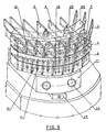
- Figure 9 represents in a larger scale a portion of the preferred embodiment of the grid support and of the template used for the final assembling in a perspective view.
- Figure 10 represents in a real scale a portion of the preferred embodiment of the circular grid structure in a partial plan view (for example for a grid support having a 3 m. outside diameter).
- Figure 11 represents schematically a partial view of a nuclear steam generator of P.W.R. reactors in a typical cross-section.
- As represented in the drawings Figure 1-10 and Figure 7a (the last Figure 7a will be taken as reference only for the external frame rings and for the strips (the preferred embodiment of the support grid, of the template used for the assembling of the support grid and of the assembling of the same in a typical steam generator, consists of the following components:
- For the support grid:
- -lower
main strips 1 in stainless steel; uppermain strips 2 in stainless steel; lowersecondary strips 3 in stainless steel; uppersecondary strips 4 in stainless steel;intermediate spacer ring 5 in stainless steel; lowersecondary spacers 6 adjacent to the secondary strip ends, in stainless steel; lower main spacers 6 m adjacent to the main strip ends in stainless steel; uppersecondary spacers 7 adjacent to the secondary strip ends, in stainless steel; uppermain spacers 7 m adjacent to the main strip ends, in stainless steel; lowerexternal box ring 8 in carbon steel; upperexternal cover ring 9 in carbon steel;lower retainer pins 10 in stainless steel between the lowersecondary spacers 6 and thespacer ring 5;lower springs 11 underlying theretainer pin 10;upper retainer pins 12 in stainless steel between the uppersecondary spacers 7 and thespacer ring 5; long joiningpins 13 in stainless steel interconnecting the lower main spacers 6m, thespacer ring 5 and the uppermain spacers 7m; joiningwelds 14 in stainless steel between the main spacers 6m-7m and thespacer ring 5; joiningpins 15 in carbon steel between the lowerexternal box ring 8 and the upperexternal cover ring 9; joiningwelds 16 in carbon steel between the joiningpins 15 and the external rings 8-9;
- -lower
- For the template used for the assembling of the support grid:
-
main template 20; auxiliarytemplate ring segments 21 for the positioning of lowersecondary spacers 6; auxiliarytemplate ring segment 22 for the positioning of the uppersecondary spacers 7; calibratedstakes 23 with threaded ends for the positioning of the main strips 1-2 and of the secondary strips 3-4 and for the fixing of the auxiliarytemplate ring segments 22; joiningscrews 24 between thering segments 21 and thetemplate 20; supportingwedges 25 for supporting thering segment 21 during the assembling of the support grid; supports 26 for supporting temporarily theexternal box ring 8 during the assembling of the support grid; mountingscrews 27 for lifting and supporting theexternal box ring 8 during its assembling on the inner frame formed ofintermediate ring 5 and spacers 6-7; - For the assembling of the grid in the steam generator represented in Figure 11:
- -wedges 30 for the alignment and for the fixing of the grid to the
casing 31;spacer 32 of proper adhesive between thecasing 31 and thewedge 30;spacer tube 33 between two facing grid supports for the axial positioning of the grids in the steam generator; throughbolts 34 for the axial fixing of a plurality ofsupport grids 40 to thetube sheet 35 of the steam generator. - The mutual position of the component part surfaces of the grid support at cold temperature (room temperature) and at high temperature (the parts expanded at the operating temperature have the same reference number of the same parts at room temperature with the added index « », as for example 5' and 5, 6 m' and 6 m) is specified hereinafter, with reference to the above mentioned drawings and assuming that the conjugate surfaces have the same reference letter index, as for example 3-o and 6-0, 4-o and 7-o; it would be noted that the play or
offset play 17 has been provided to allow the stainless steel circular grid structure to expand radially during periods of normal and high thermal activity, relative to the slower thermal expanding external frame in carbon steel of the support: - a) conjugate surfaces in surface-to-surface contact only at cold temperature:
- external cylindrical dog surface 8-t of the lower external
box frame ring 8 and the internal generally cylindrical surfaces 6-t of the outer projecting portion of thelower spacers 6, 6m; external cylindrical surfaces 9-t of the internal dog 9-a of the upper externalcover frame ring 9 and the internal generally cylindrical surfaces 7-t of the outer projecting portion of theupper spacers
- external cylindrical dog surface 8-t of the lower external
- b) Conjugate surfaces in surface-to-surface contact or facing each other with a substantially small play therebetween only at operating temperature (the
play 17 is reduced to said substantially small play 17'):- -external generally cylindrical surfaces 6-s of the
lower spacers 6, 6m and the internal cylindrical box surface 8-s of the lower externalbox frame ring 8; external cylindrical surface 5-s of the independentintermediate frame ring 5 and the internal cylindrical box surface 8-s of the lower externalbox frame ring 8; external generally cylindrical surfaces 7-s of theupper spacers box frame ring 8;
- -external generally cylindrical surfaces 6-s of the
- c) Conjugate surfaces facing each other with a substantially small play therebetween at cold and high temperature:
- - internal annular dog surface 8-p of the lower external
box frame ring 8 and the external annular reticular portion surface formed of the lower strip end portion surfaces 1-p and 3-p of thelower strips external cover ring 9 and the external annular reticular portion surface formed of the upper strip end portion surfaces 2-p and 4-p of theupper strip
- - internal annular dog surface 8-p of the lower external
- d) Conjugate surfaces in surface-to-surface contact at cold and high temperature or facing each other with a substantially small play therebetween at high temperature, as the case of a thin layer of metal adhesive therebetween being melted at high temperature as hereinafter described or as the case of a small difference of the thermal expansion coefficient of the fitting materials:
- -axially and generally radially extending surfaces 6-o of the lower spacers 6, 6m and the strip end surfaces 1-o, 3-o of the lower strips 1, 3 respectively; axially and generally radially extending surfaces 7-o of the upper spacers 7m, 7 and the strip end surfaces 2-o, 4-o of the upper strips 2, 4 respectively; upper strip end surfaces 1-r, 3-r of the lower strip end 1, 3 respectively and the lower annular surface 5-r of the independent intermediate frame ring 5; lower strip end surfaces 2-v, 4-v of the upper strip 2, 4 respectively and the upper annular surface 5-v of the independent intermediate frame ring 5; axially and generally tangential extending end surfaces 1-c of the lower main strip 1 and the internal cylindrical surface 5-c of the independent intermediate frame ring 5 (this ring assuming position 5 at cold temperature, Figure 5, and position 5' shown in dotted line at operating temperature, Figure 6); axially and generally tangential extending strip end surfaces 2-c of the upper main strip 2 and the internal cylindrical surface 5-c of the independent intermediate frame ring 5 (this ring assuming two different positions as above described); external lower annular flange surface 9-c of the upper external cover frame ring 9 and the upper external annular flange surface 8-c of the lower external box frame ring 8 (said surfaces being always in surface-to-surface contact both at room and operating temperatures); internal cylindrical surface 9-u of the external dog 9-b of the upper external cover frame ring 9 and the upper external cylindrical surface 8-u of the lower external box frame ring 8 (said surfaces being generally in surface-to-surface contact both at room and operating temperature); upper internal annular flange surface 8-i of the lower external box frame ring 8 and the lower annular surface 6-i of the lower spacers 6, 6m (said surfaces having generally a substantially small play therebetween at operating temperature); internal lower annular flange surface 9-i of the external cover frame ring 9 and the upper annular surface 7-i of the upper spacers 7, 7m (said surfaces having generally a substantially small play at operating temperature).
- It should be noted that the external generally cylindrical surfaces 1-s, 2-s, 3-s, 4-s, 5-s, of the strip ends 1, 2, 3, 4 and independent
intermediate frame ring 5 respectively, are generally aligned to each other both at room and operating temperatures, that is all said surfaces are always positioned on a unique envelopping cylindrical surface. - As shown in the drawings and as is well known, the milled slots of the main strips are equally mutually spaced and are of two kinds:
- main slots-with a depth equal to half of the width of the strip, for the coupling of the
main strips - -secondary slots-with a depth equal to 1/3 of the width of the strip able to receive the
secondary strips - The assembling of the individual strips, which will then form the grid, is carried out on a horizontal plane of a
template 20 with the aid of an assembly jig. At each main crossing, this jig hasstakes 23 assuring the position of each intersection for all main strips. A normal grid of this type comprises, for example, two dozen main or carrying strips and eight secondary strips for each main strip, the finished grid having a diameter of about 3m. - The lower
main strips 1 are first placed on theassembly template 20; at the bottom such strips terminate with an L end 1-o covering piece 6-m at the conjugate surface 6-o thereof. - Now
piece 5 in stainless steel is assembled,piece 5 being a continuous ring rigidly joined to the main spacers 6-m and 7-m (by means like throughpins 13 and/or by welds 14), whereupon and between the adjacent main spacers 7-m the uppermain strips 2 are assembled, these strips also having an L-end 2-o downwards facing. That is the end thereof is such to cover piece 7-m, at the conjugate surface thereof 7-o. - Finally the lower and the upper
secondary strips intermediate frame ring 5. - Between the adjacent strip end surfaces 3-o of each pair of secondary lower strips 3 a lower
secondary spacer block 6 is inserted; in the axial extending blind hole 6-z thereof has been previously assembled aspring 11 and thereupon apin 10, so that thespacer 6 is fixed by pushing out of thepin 10 in the groove 5-v of thering 5 under the action of saidspring 11, when saidspacer 6 has been pushed in its definitive position under thering 5 and stopped by the auxiliaryassembly ring segment 21. Also between the adjacent strip end surfaces 4-o of each pair of the secondaryupper strips 4 an uppersecondary spacer block 7 is now inserted and stopped by the auxiliaryassembly ring segment 22, thereafter thepin 12 is inserted in the axial extending through hole 7-z of thespacer 7 and in the groove 5-x of theframe ring 5. - The surfaces of mutual contact between the ends of the
strips spacers 6, 6-m and 7, 7-m, as well the surfaces 5-r, 5-v ofring 5 contacting the spacers, have been previously prepared for receiving a layer of metal paste or glue (for example, base and reactor polymerizing under cold or slightly warm condition) of hot water soluble type, or eventually soluble with other solvents. This paste or glue completely locks the parts of the grid together forming a rigid inner frame. - The auxiliary
assembly ring segments - When the generator is set in operation, the flow of water and saturated steam, for example at a temperature of 150°-200°C, melts the glue or paste and the strips and the intermediate framework are free to expand, that is strips 1, 2, 3 and 4 of stainless steel, the
independent frame ring 5 interengaged withspacers 6, 6-m and 7, 7-m also in stainless steel slide together at substantially same rate with little or no relative thermal expansion, the required clearances being provided. Thus the said last mentioned parts assume the position 5', 6-m', 7-m' as shown in the drawing Figure 6. Thus the external frame components, that ispieces - The mutual position of the lower and upper dogs 8-a and 9-a of the box frame ring and cover frame ring respectively with the conjugate lower and upper spacer surfaces 6-t and 7-t respectively is such that at room temperature the outer surfaces 8-t and 9-t of the dogs 8-a and 9-a respectively contact rigidly the inner conjugate surfaces 6-t and 7-t of the spacers, as shown in the drawing, while at operating temperature, for example 300°C, between said outer cylindrical surfaces 8-t and 9-t of the dogs 8-a and 9-a respectively and the inner conjugate cylindrical surfaces 6-t and 7-t of the lower and upper spacers respectively is
sufficient play 18 to allow flow of thehot water 19 through the lower and upper set of the radial cleaning ducts 6-e and 7-e respectively, between the adjacent spacers, overlying the strip ends, and through the axial extending interspaced holes 8-e, 9-e, formed through the external frame ring annular region facing theplay 17 between said external frame rings and the inner frame. - Also the
glue layer 32 applied on the external surface of thewedges 30 inserted about the grid will unglue and leave a free clearance equal to the thickness of the previously inserted glue or paste. This enables a free axial sliding between the pack of grids maintained spaced apart from one another by spacers 33 made of stainless steel and thecasing 31 of carbon steel. It should be noted that said dogs 8-a and 9-a on the external frame serve also the purpose of retaining the spacers, when unglued, during operation, in the case of breakage of the interconnecting pins 10 and 12. - An alternative embodiment of the support grid is represented in the drawings Figure 5a-6a and 7a. Most of the component parts shown in these drawings are the same represented in the drawings Figure 1-10 and therefore bear the same reference number.
- The unique difference to be noted in the above mentioned drawings is the different embodiment of the inner frame, that consists of a single
intermediate spacer ring 45 in stainless steel having a height equal to the sum of the partial height oflower spacer 6 or 6-m,intermediate spacer ring 5 andupper spacer 7 or 7-m represented in the Figure 1-10, saidsingle ring 45 having a set of lower milled teeth 45-o generally radially extending and a set of upper milled teeth 45-o' also generally radially extending, both sets of teeth provided to receive in the space-like slot (45r; 45v) between adjacent teeth the ends 1-o, 3-o and 2-o, 4-o of the lower and upper strips respectively. - For this alternative embodiment of the support grid the mutual position of the component part surfaces will be the same as above described for the preferred embodiment, assuming that the lower teeth 45-o and the upper teeth 45-o' of Figure 7a perform the same functions as the lower and
upper spacers 6, 6-m and 7, 7-m of Figure 7 respectively and the conjugate contacting surfaces thereof with the outer cylindrical surfaces 8-t and 9t of the dogs 8-a and 9-a respectively are the tooth inner lower and upper cylindrical surfaces 45-t and 45-t' respectively, so also as the contacting conjugate surfaces of said teeth with the annular flange surfaces 8-i and 9-i are the lower and the upper tooth annular surfaces 45-i and 45-i' respectively. - The material described above for the preferred and the alternative embodiment of the grid support may also be substituted by equivalent material and for each pair of said different materials for the circular grid structure and for the outer box frame there will be suitable play therebetween to allow free differential thermal expansion in the area of the joint.
- Description of the preferred embodiment of the template for the final assembling of the above described supporting grid.
- As represented in the drawing Figure 8; a template for the final assembling of the finished component parts of the supporting grid is comprising:
- a) an horizontal rigid cylindrical
main template 20 having rigidly connected, by welding, at the peripheral annular lower surface thereof, shaped interspacedsupport legs 26, the external cylindrical surface 26-c of the inner axially extending portion 26-b thereof being aligned with the external cylindrical surface 20-c of saidmain template 20, the annular radially extending portion 26-a of said L-shapedsupport legs 26 being provided to support temporarily the lower externalbox frame ring 8 of the supporting grid, during the final assembling thereof, and incorporating threaded interspaced through axial holes 26-e provided to receive the mating lifting screws 27 for lifting said lower externalbox frame ring 8 along the said external cylindrical surface 26-c of saidsupport legs 26 and successively along said external cylindrical surface 20-c of saidmain template 20. - b) auxiliary template ring segments 21, the inner cylindrical surface thereof 21-c being tight interconnected with the conjugate external cylindrical surface 20-c of said main template 20, by the fixing screws 24, said auxiliary ring segments 21 having an internal annular dog 21-a axially extending, the upper radially extending annular surface thereof 21-p being aligned with the horizontal upper surface 20-p of said main template 20, the external cylindrical surface 21-t of said ring segment dog 21-a being aligned with the inner cylindrical surface 5-c of said intermediate frame ring 5, said dog 21-a having an axial height 21-t equal to the height of the internal annular dog 8-t of the said external lower box frame ring 8 and being provided to allow the exact radial positioning of the inner frame assembly 5, 6, 7 or 45, 45-o, 45-o' on said auxiliary template ring segments 21 for purpose of successively dismounting said template ring segments 21, previously having dismounted the underlaying conjugate supporting wedges 25 (disposed between said ring segments 21 and said external lower box frame ring 8) and the conjugate fixing screws 24, and successively assembling of said external lower box frame ring 8 on said intermediate frame-work assembly 5, 6, 7 or 45, 45-o, 45-0' by operating said lifting screws 27.
- c) auxiliary
template ring segments 22 supported and fixed on calibratedstakes 23, said stakes axially extending, peripherally interspaced and screwed to saidmain template 20, saidring segments 22 having the external cylindrical surface 22-t aligned with the internal cylindrical surface 5-c of saidintermediate frame ring 5 and being provided to allow the exact radial positioning of saidintermediate framework assembly - Assembly of the alternative embodiment is carried out as above described. In this case however the inner frame consist only of the
single ring 45 so that no spacers are inserted.
Claims (8)
Applications Claiming Priority (2)
| Application Number | Priority Date | Filing Date | Title |
|---|---|---|---|
| IT23511/78A IT1096096B (en) | 1978-05-17 | 1978-05-17 | GUIDE-SUPPORT OF THE GRID TYPE FOR PIPES FOR STEAM GENERATORS |
| IT2351178 | 1978-05-17 |
Publications (2)
| Publication Number | Publication Date |
|---|---|
| EP0005681A1 EP0005681A1 (en) | 1979-11-28 |
| EP0005681B1 true EP0005681B1 (en) | 1983-05-18 |
Family
ID=11207738
Family Applications (1)
| Application Number | Title | Priority Date | Filing Date |
|---|---|---|---|
| EP79810037A Expired EP0005681B1 (en) | 1978-05-17 | 1979-05-14 | Tube support grid and method of making |
Country Status (7)
| Country | Link |
|---|---|
| US (1) | US4371035A (en) |
| EP (1) | EP0005681B1 (en) |
| JP (1) | JPS5514493A (en) |
| CA (1) | CA1131516A (en) |
| DE (1) | DE2965423D1 (en) |
| ES (1) | ES480607A1 (en) |
| IT (1) | IT1096096B (en) |
Families Citing this family (21)
| Publication number | Priority date | Publication date | Assignee | Title |
|---|---|---|---|---|
| US4299276A (en) * | 1980-04-21 | 1981-11-10 | Phillips Petroleum Company | Heat exchanger having radial support |
| IT8025181A0 (en) * | 1980-10-08 | 1980-10-08 | Ponte Nizza Pavia | ANTI-SEISMIC GRID SUPPORT FOR STEAM GENERATORS PIPES, HEAT EXCHANGERS, PARTICULARLY FOR PWR TYPE STEAM GENERATORS. |
| US4485069A (en) * | 1982-01-20 | 1984-11-27 | Westinghouse Electric Corp. | Moisture separator reheater with round tube bundle |
| FR2523712B1 (en) * | 1982-03-18 | 1985-11-15 | Cass International Gmbh | INTERMEDIATE SUPPORT GRID FOR TUBE BEAM HEAT EXCHANGERS |
| US4503903A (en) * | 1982-07-06 | 1985-03-12 | Westinghouse Electric Corp. | Heat exchanger tube sheet radial support |
| US4711758A (en) * | 1984-12-24 | 1987-12-08 | Westinghouse Electric Corp. | Spent fuel storage cask having basket with grid assemblies |
| DE3540229A1 (en) * | 1985-11-13 | 1987-05-14 | MAN Gutehoffnungshütte GmbH, 4200 Oberhausen | PIPE GRID FOR GUIDING THE TUBES OF EXAMPLE STEAM GENERATORS |
| DE3631886A1 (en) * | 1986-09-19 | 1988-03-31 | Gutehoffnungshuette Man | SPACER FOR GRID ROD OF A PIPE GRID IN HEAT EXCHANGERS |
| US6240156B1 (en) * | 1997-08-29 | 2001-05-29 | General Electric Company | Top guide grid attachment for a boiling water reactor |
| US7665270B1 (en) * | 2007-08-06 | 2010-02-23 | LatticeStix, Inc. | Lattice structure assembly having members with overlapping end sections connected by connection rods |
| US9163857B2 (en) * | 2009-02-12 | 2015-10-20 | Babcock Power Services, Inc. | Spray stations for temperature control in solar boilers |
| AU2010213745B2 (en) * | 2009-02-12 | 2016-03-17 | Babcock Power Services Inc. | Panel support system for solar boilers |
| US8316843B2 (en) | 2009-02-12 | 2012-11-27 | Babcock Power Services Inc. | Arrangement of tubing in solar boiler panels |
| US9134043B2 (en) | 2009-02-12 | 2015-09-15 | Babcock Power Services Inc. | Heat transfer passes for solar boilers |
| US8893714B2 (en) | 2009-02-12 | 2014-11-25 | Babcock Power Services, Inc. | Expansion joints for panels in solar boilers |
| US8356591B2 (en) * | 2009-02-12 | 2013-01-22 | Babcock Power Services, Inc. | Corner structure for walls of panels in solar boilers |
| US8397710B2 (en) * | 2009-02-12 | 2013-03-19 | Babcock Power Services Inc. | Solar receiver panels |
| US8517008B2 (en) * | 2009-02-12 | 2013-08-27 | Babcock Power Services, Inc. | Modular solar receiver panels and solar boilers with modular receiver panels |
| US20110079217A1 (en) * | 2009-02-12 | 2011-04-07 | Babcock Power Services, Inc. | Piping, header, and tubing arrangements for solar boilers |
| US8573196B2 (en) | 2010-08-05 | 2013-11-05 | Babcock Power Services, Inc. | Startup/shutdown systems and methods for a solar thermal power generating facility |
| US9038624B2 (en) | 2011-06-08 | 2015-05-26 | Babcock Power Services, Inc. | Solar boiler tube panel supports |
Family Cites Families (9)
| Publication number | Priority date | Publication date | Assignee | Title |
|---|---|---|---|---|
| US3361197A (en) * | 1966-02-03 | 1968-01-02 | Du Pont | Tube support |
| US3420297A (en) * | 1967-04-25 | 1969-01-07 | Combustion Eng | Heat exchanger tube support and spacing structure |
| DE2204280A1 (en) * | 1972-01-29 | 1973-08-30 | Babcock & Wilcox Ag | HEAT EXCHANGER WITH PIPES LONG IN RELATION TO THE PIPE DIAMETER |
| DE2263056C3 (en) * | 1972-12-22 | 1980-10-23 | Siemens Ag, 1000 Berlin Und 8000 Muenchen | Spacer grille for tube bundle heat exchangers |
| DE2316133C2 (en) * | 1973-03-30 | 1983-11-17 | Siemens AG, 1000 Berlin und 8000 München | Shell and tube heat exchanger |
| IT981824B (en) | 1973-04-02 | 1974-10-10 | Breda Termomeccanica E Locomot | GRID-TYPE PIPE SUPPORT GUIDE WITH DIFFERENT ELASTIC JOINT FOR STEAM GENERATORS HEAT EXCHANGERS AND DIFFERENT APPLIANCES |
| IT1038778B (en) * | 1975-06-09 | 1979-11-30 | Breda Termomeccanica Spa | METHOD FOR MAKING A GRID CONSISTING OF TWO DIFFERENT MATERIALS ABLE TO BE INITIALLY RIGID WHILE AFTER COMMISSIONING IT ALLOWS DIFFERENTIAL THERMAL EXPANSION |
| FR2373770A1 (en) | 1976-12-07 | 1978-07-07 | Breda Termomeccanica Spa | PROCESS FOR CONSTRUCTING A RIGID GRID CAPABLE OF DIFFERENTIAL THERMAL EXPANSIONS AND GRID THUS OBTAINED ACCORDING TO THIS PROCEDURE |
| IT1065374B (en) * | 1976-12-21 | 1985-02-25 | Breda Termomeccanica Spa | SUPPORT GRID FOR TUBES AND ITS ASSEMBLY IN A STEAM GENERATOR OR SIMILAR |
-
1978
- 1978-05-17 IT IT23511/78A patent/IT1096096B/en active
-
1979
- 1979-05-11 CA CA327,459A patent/CA1131516A/en not_active Expired
- 1979-05-14 DE DE7979810037T patent/DE2965423D1/en not_active Expired
- 1979-05-14 EP EP79810037A patent/EP0005681B1/en not_active Expired
- 1979-05-16 JP JP6023379A patent/JPS5514493A/en active Granted
- 1979-05-16 ES ES480607A patent/ES480607A1/en not_active Expired
- 1979-05-16 US US06/039,680 patent/US4371035A/en not_active Expired - Lifetime
Also Published As
| Publication number | Publication date |
|---|---|
| US4371035A (en) | 1983-02-01 |
| ES480607A1 (en) | 1980-01-16 |
| JPS5514493A (en) | 1980-01-31 |
| IT7823511A0 (en) | 1978-05-17 |
| CA1131516A (en) | 1982-09-14 |
| IT1096096B (en) | 1985-08-17 |
| EP0005681A1 (en) | 1979-11-28 |
| DE2965423D1 (en) | 1983-07-07 |
| JPS5652225B2 (en) | 1981-12-10 |
Similar Documents
| Publication | Publication Date | Title |
|---|---|---|
| EP0005681A1 (en) | Tube support grid and method of making | |
| CA1048760A (en) | Method of mounting a grill to accommodate thermal expansion | |
| EP0304724B1 (en) | Nuclear fuel assembly grid | |
| JP2521002B2 (en) | Swirl vanes for addition to spring metal grid spacers and methods of adding swirl vanes to spring metal grid spacers | |
| US3941188A (en) | Tube spacer grid for a heat-exchanger tube bundle | |
| US4036461A (en) | Supporting grid for pipes | |
| JP3605171B2 (en) | Reactor fuel assembly | |
| JPH01130939A (en) | Honeycomb structure assembly | |
| JPS6023280B2 (en) | Pipe row holding device inside the container | |
| JPS6142834B2 (en) | ||
| JPH032436B2 (en) | ||
| JPH0752637Y2 (en) | Fuel assembly | |
| US4059483A (en) | Nuclear fuel assembly seismic amplitude limiter | |
| CA2078809A1 (en) | Spacer sleeve for nuclear fuel assembly | |
| US4381815A (en) | Thermal shock resistant honeycomb structures | |
| JPH0310196A (en) | Fuel-element support grid | |
| US4174123A (en) | Vessel penetration apparatus | |
| CA1185965A (en) | Rotor construction for rotary regenerative air heater | |
| US4786463A (en) | Emergency heat exchanger for cooling the primary fluid of a nuclear reactor, and a process for assembling this heat exchanger | |
| EP0049691A2 (en) | Earthquake-proof tube support grid | |
| JPH0321878B2 (en) | ||
| SU1334039A1 (en) | Remote tube plate for heat exchanger | |
| US3287231A (en) | Fuel element assembly for a neutronic reactor | |
| US4330028A (en) | Seal column apparatus and method | |
| US3636674A (en) | Insulation module with superposed deformed core sheets |
Legal Events
| Date | Code | Title | Description |
|---|---|---|---|
| PUAI | Public reference made under article 153(3) epc to a published international application that has entered the european phase |
Free format text: ORIGINAL CODE: 0009012 |
|
| AK | Designated contracting states |
Designated state(s): BE DE GB SE |
|
| 17P | Request for examination filed | ||
| GRAA | (expected) grant |
Free format text: ORIGINAL CODE: 0009210 |
|
| RAP1 | Party data changed (applicant data changed or rights of an application transferred) |
Owner name: SOLIGNO, VINCENZO |
|
| AK | Designated contracting states |
Designated state(s): BE DE GB SE |
|
| PG25 | Lapsed in a contracting state [announced via postgrant information from national office to epo] |
Ref country code: SE Free format text: THE PATENT HAS BEEN ANNULLED BY A DECISION OF A NATIONAL AUTHORITY Effective date: 19830518 Ref country code: BE Effective date: 19830518 |
|
| REF | Corresponds to: |
Ref document number: 2965423 Country of ref document: DE Date of ref document: 19830707 |
|
| PLBE | No opposition filed within time limit |
Free format text: ORIGINAL CODE: 0009261 |
|
| STAA | Information on the status of an ep patent application or granted ep patent |
Free format text: STATUS: NO OPPOSITION FILED WITHIN TIME LIMIT |
|
| 26N | No opposition filed | ||
| GBPC | Gb: european patent ceased through non-payment of renewal fee | ||
| PG25 | Lapsed in a contracting state [announced via postgrant information from national office to epo] |
Ref country code: DE Effective date: 19850201 |
|
| PG25 | Lapsed in a contracting state [announced via postgrant information from national office to epo] |
Ref country code: GB Effective date: 19881118 |