EP0005317B1 - Data receiving apparatus - Google Patents
Data receiving apparatus Download PDFInfo
- Publication number
- EP0005317B1 EP0005317B1 EP79300523A EP79300523A EP0005317B1 EP 0005317 B1 EP0005317 B1 EP 0005317B1 EP 79300523 A EP79300523 A EP 79300523A EP 79300523 A EP79300523 A EP 79300523A EP 0005317 B1 EP0005317 B1 EP 0005317B1
- Authority
- EP
- European Patent Office
- Prior art keywords
- word
- flag bit
- data
- data receiving
- receiving apparatus
- Prior art date
- Legal status (The legal status is an assumption and is not a legal conclusion. Google has not performed a legal analysis and makes no representation as to the accuracy of the status listed.)
- Expired
Links
Images

Classifications
-
- H—ELECTRICITY
- H04—ELECTRIC COMMUNICATION TECHNIQUE
- H04L—TRANSMISSION OF DIGITAL INFORMATION, e.g. TELEGRAPHIC COMMUNICATION
- H04L1/00—Arrangements for detecting or preventing errors in the information received
- H04L1/08—Arrangements for detecting or preventing errors in the information received by repeating transmission, e.g. Verdan system
Definitions
- the present invention relates to data receiving apparatus of the type which receives and stores a block of data consisting of a plurality of words, and which is used to receive repetitively transmitted blocks of data. From the point of view of the receiving apparatus, each transmission constitutes a refresh cycle.
- An example of such apparatus is a teletext receiver.
- the invention is not restricted to such use, it will be described largely in terms of the U.K. "Broadcast Teletext Specification" as set forth in a document so entitled, published September 1976 by us and others.
- a block of data is a page of data to be displayed on the screen of a television receiver incorporating or coupled to the data receiving apparatus.
- the words or bytes correspond to characters and consists each of 7 data bits plus an odd parity bit.
- the object of the present invention is to provide data receiving apparatus which makes use of the repeated transmissions of blocks of data to effect error correction without the use of parity checks and without the need for long-term recording or observations, as would be necessary if a majority decision technique were to be employed.
- French patent specification 2,297,528 for "Receiver for majority detection of repeated messages” describes a system wherein a previously received byte is stored in a buffer register and compared in a comparator with a currently received byte. When a first match occurs, the buffer register contents are frozen and a flag bit is set. A second match then, if received in a total of seven receptions, sets a second flag bit to signal valid byte.
- this system does not enable the best choice between using the new and the old byte when a mismatch occurs.
- non-cyclic count operation an operation bounded by limit states in both senses; once a limit state is reached, further count operations in the corresponding sense do not cause any further change of state.
- the flag bit is counted down to 0, if not already there. If the old flag bit was 1 (meaning that the bytes in the two preceding refresh cycles matched) it is assumed that the old byte is likely to be correct and accordingly (row 4) this is the byte which is stored. If the old flag bit was 0 the new byte is clearly preferred and is thus the byte which is stored (row 3).
- the apparatus can be left to adapt to the new block as follows, (ignoring the fact that some particular bytes may not change):
- the apparatus can, however, be modified to adapt more quickly, cutting out Refresh Cycle 1 of the above scheme.
- Use is made of a signal, which is referred to as UPDATE and which indicates that the block is a new or changed block, to force the flags to 0 with storage of the new bytes, regardless of the states of the old flags and of the match conditions, (row 5 of Table 1).
- the invention can be extended to employ more than one flag bit per byte. For example two bits could be counted up to 1 by matches and down to 00 by mismatches, 00 and 11 representing limit states corresponding to minimum confidence and maximum confidence respectively in the old byte. It may then be decided that the new byte is always stored unless the old flag is 11 or it could be decided that the new byte is stored when the old flag is 00 or 01, while the old byte is stored when the old flag is 10 or 11. It should be emphasised that, although the flag bits store a history going back over several cycles, only a single block of data is stored at any one time.
- the illustrated apparatus is part of an otherwise conventional teletext receiver which demodulates 8-bit characters (bytes) from a television signal and feeds the characters as bit-parallel input data DI to a data register 10 which has one address location per character.
- An addressing circuit 11 addresses these locations in sequence in synchronism with the received characters, as is conventional in teletext receivers. Such addressing may be by random access techniques or by employment of a bit-parallel recirculating shift register as the data register 10, as is well known in the art.
- the register locations are accessed in sequence, the characters are read out and rewritten, the read-out characters constituting output data DO which is conventionally fed to a decoder for display on a television screen.
- the comparator 12 can compare only the 7 data bits of the character if the 8th bit has no information content. If, as proposed in the aforementioned application 41265/77, the 8th bit does have information content, the comparator should compare all 8 bits.
- the signal M constitutes one input to a logic circuit 13.
- a third input is F(n), namely the old flag bit from a flag bit register 14 which is addressed in synchronism with the register 10 so that, as each character of D(n) is presented for read/rewrite, so is the corresponding flag bit of F(n).
- the circuit 13 also provides F(N + 1) for writing back into the register 14.
- the circuit 13 is constructed in accordance with the truth table constituting Table 2.
- the non-cyclic counter need not necessarily increment and decrement in unit steps and the sizes of the steps may be functions of the state of the counter.
- a status circuit 16 is connected to the output of the flag register and controls a signal device 17, which could be a green lamp lit when all flag bits are 1 or a red lamp lit when any flag bit is 0.
- the status circuit could comprise parallel AND logic or be a serial device such as a bistable circuit which is reset at the beginning of each refresh cycle and set by any zero flag bit in the serial output F(n) from the register 14.
- a substitute character such as "delete” can be displayed when a flag bit is zero, just as a substitute character is displayed in known teletext systems until a parity check is satisfied.
- the stored character can be displayed but with some means of drawing attention to the doubt attaching thereto, e.g. display and background colours transposed, display flashing quickly or character underlined. All such techniques are within the capabilities of state of the art teletext receivers.
- the data selector 15 selects D(n) or DI for writing into the register 10. In practice the same result may well be achieved by enabling a Di write operation when the new byte is selected, otherwise leaving the contents of the register 10 unchanged. The selector 15 will not be required and the signal S will act as "write-enable" to the register 10.
Landscapes
- Engineering & Computer Science (AREA)
- Computer Networks & Wireless Communication (AREA)
- Signal Processing (AREA)
- Television Systems (AREA)
- Detection And Prevention Of Errors In Transmission (AREA)
- Communication Control (AREA)
- Circuits Of Receivers In General (AREA)
Description
- The present invention relates to data receiving apparatus of the type which receives and stores a block of data consisting of a plurality of words, and which is used to receive repetitively transmitted blocks of data. From the point of view of the receiving apparatus, each transmission constitutes a refresh cycle. An example of such apparatus is a teletext receiver. Although the invention is not restricted to such use, it will be described largely in terms of the U.K. "Broadcast Teletext Specification" as set forth in a document so entitled, published September 1976 by ourselves and others. In this context a block of data is a page of data to be displayed on the screen of a television receiver incorporating or coupled to the data receiving apparatus. Furthermore the words or bytes correspond to characters and consists each of 7 data bits plus an odd parity bit.
- One of the strengths of the U.K. Broadcast Teletext System is the operation of the receivers in such a way that any isolated errors in a received and displayed page are usually corrected automatically when the page is next transmitted, as new information takes precedence over old. Only character bytes satisfying the odd-parity check are written into storage and, until the first such byte has been received for each position in a new page, a substitute character, normally a space is displayed to give an indication of error. Although this correction by repeated transmission could be used to advantage simply by recording the page as received many times and using a character-by-character 'majority' decision, the use of odd-parity detection as described above does give a more immediate indication of a correctly received page. Nevertheless, there are circumstances where this protection is clearly insufficient, and methods offering improved security have already been described in our British patent application 12698/77, corresponding to German Offenlegungsschrift 2 812 435 published 28.9.78.
- In order to offer the possibility of an extended alphabet of up to, perhaps, 200 characters for use in a common European teletext system it has been proposed in our British patent application 41265/77, (the corresponding German Offenlegungsschrift 2 821 886 is due to be published in May 1979), that almost the entire range of 8-bit codes be used for characters, the odd-parity codes being used in the same way as is set forth in the document "Broadcast Teletext Specification" in order to maintain compatibility. (CEEFAX is our Trade Mark for our broadcast teletext system). Thus a basic character set (including control characters) is provided by the odd-parity codes. At least some additional characters are transmitted as even-parity codes. This proposal precludes the use of a simple parity check to detect errors although more complex methods of error detection such as are described in the aforesaid application No 12698/77 could still be used.
- The object of the present invention is to provide data receiving apparatus which makes use of the repeated transmissions of blocks of data to effect error correction without the use of parity checks and without the need for long-term recording or observations, as would be necessary if a majority decision technique were to be employed.
- In this respect, French patent specification 2,297,528 for "Receiver for majority detection of repeated messages" describes a system wherein a previously received byte is stored in a buffer register and compared in a comparator with a currently received byte. When a first match occurs, the buffer register contents are frozen and a flag bit is set. A second match then, if received in a total of seven receptions, sets a second flag bit to signal valid byte. However this system does not enable the best choice between using the new and the old byte when a mismatch occurs.
- Accordingly the starting point of the present invention is set forth in the introductory part of
claim 1 and the invention is characterised as further set forth inclaim 1. - By a non-cyclic count operation, is meant an operation bounded by limit states in both senses; once a limit state is reached, further count operations in the corresponding sense do not cause any further change of state.
- Of particular interest is the simplest possible case in which there is a single flag bit per byte capable of assuming only the
states 0 and 1 which can be arbitrarily assigned to match and mismatch conditions. In the example below it is assumed that match = 1 and mismatch = 0. Operation can then be as set out in Table 1.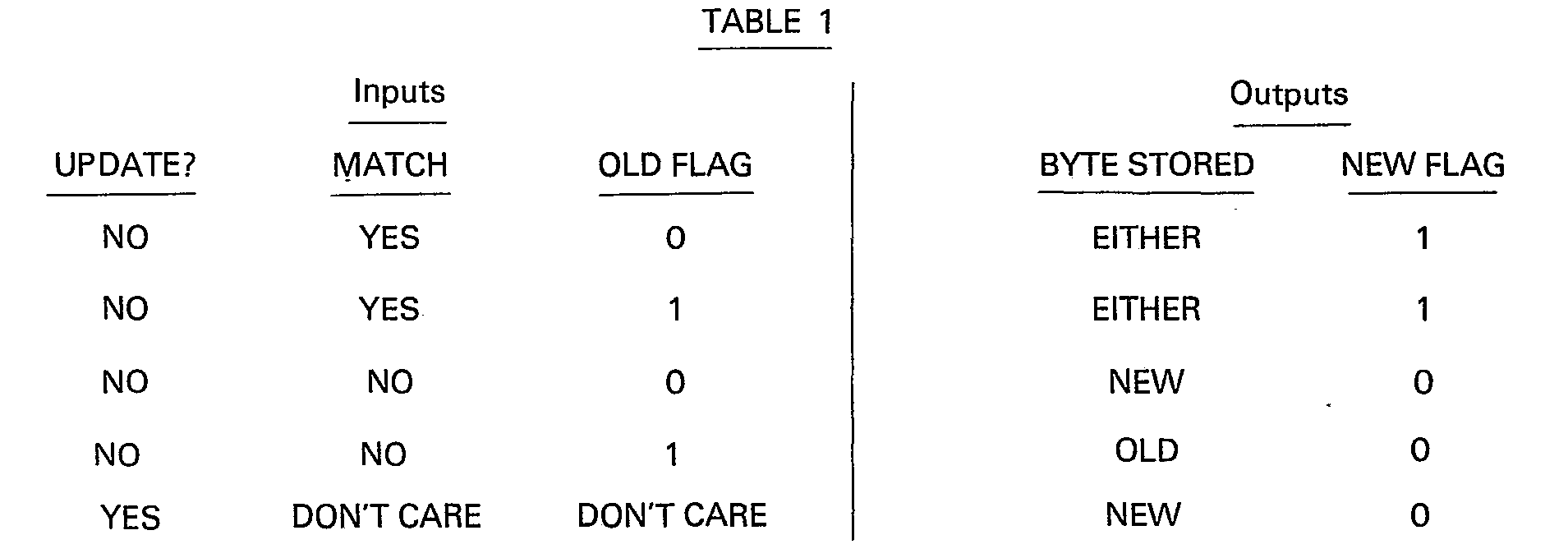
- The meaning of UPDATE will be explained below. Consider firstly
rows 1 to 4 of Table 1. If the old (currently stored) byte matches the new (currently received byte), the existing flag state does not matter and (rows 1 and 2) the newly stored byte may be either the old byte or the new byte, since they are the same. Moreover the flag bit counts up to 1, if not already there to indicate that a match occurred. Although either byte can logically be stored, a decision has to be taken which to store as a matter of hardware design. - If the old and new bytes do not match, (rows 3 and 4 of Table 1), the flag bit is counted down to 0, if not already there. If the old flag bit was 1 (meaning that the bytes in the two preceding refresh cycles matched) it is assumed that the old byte is likely to be correct and accordingly (row 4) this is the byte which is stored. If the old flag bit was 0 the new byte is clearly preferred and is thus the byte which is stored (row 3).
- From time to time the block of data may be changed. The apparatus can be left to adapt to the new block as follows, (ignoring the fact that some particular bytes may not change):
-
Refresh Cycle 1.- Old flags all at 1 are all set to 0 but the old block of data is retained (row 4 of Table 1).
- Refresh Cycle 2.
- Flags remain at 0 but the new block of data is stored (row 3 of Table 1).
- Refresh Cycle 3.
- Flags set to 1 and either block of data is stored (
row 1 of Table 1).
- Flags set to 1 and either block of data is stored (
- Refresh Cycles 4, etc.
- Flags remain at 1 and either block of data is stored (row 2 of Table 1).
- The apparatus can, however, be modified to adapt more quickly, cutting out Refresh
Cycle 1 of the above scheme. Use is made of a signal, which is referred to as UPDATE and which indicates that the block is a new or changed block, to force the flags to 0 with storage of the new bytes, regardless of the states of the old flags and of the match conditions, (row 5 of Table 1). - The invention can be extended to employ more than one flag bit per byte. For example two bits could be counted up to 1 by matches and down to 00 by mismatches, 00 and 11 representing limit states corresponding to minimum confidence and maximum confidence respectively in the old byte. It may then be decided that the new byte is always stored unless the old flag is 11 or it could be decided that the new byte is stored when the old flag is 00 or 01, while the old byte is stored when the old flag is 10 or 11. It should be emphasised that, although the flag bits store a history going back over several cycles, only a single block of data is stored at any one time.
- It may be important for the user of the receiver to know whether the currently stored block of data has complete integrity or not; this may be signalled on the basis of the collective state of the flag bits as explained below.
- An embodiment of the invention will now be described, by way of example, with reference to the block diagram constituting the sole figure of the accompanying drawing.
- The illustrated apparatus is part of an otherwise conventional teletext receiver which demodulates 8-bit characters (bytes) from a television signal and feeds the characters as bit-parallel input data DI to a
data register 10 which has one address location per character. An addressing circuit 11 addresses these locations in sequence in synchronism with the received characters, as is conventional in teletext receivers. Such addressing may be by random access techniques or by employment of a bit-parallel recirculating shift register as thedata register 10, as is well known in the art. As the register locations are accessed in sequence, the characters are read out and rewritten, the read-out characters constituting output data DO which is conventionally fed to a decoder for display on a television screen. - The read-out characters are also fed back as data D(n), i.e. data for the nth refresh cycle, to a
comparator 12 which compares each old character of D(n) with the corresponding new character of DI producing a match signal M = 1 if the characters match or M = 0 if they do not match. Thecomparator 12 can compare only the 7 data bits of the character if the 8th bit has no information content. If, as proposed in the aforementioned application 41265/77, the 8th bit does have information content, the comparator should compare all 8 bits. - The signal M constitutes one input to a
logic circuit 13. A second input is UI where UI = 1 means UPDATE. This signal is provided when a page is changed or is updated as indicated by the update control bit referred to in the document "Broadcast Teletext Specification". A third input is F(n), namely the old flag bit from aflag bit register 14 which is addressed in synchronism with theregister 10 so that, as each character of D(n) is presented for read/rewrite, so is the corresponding flag bit of F(n). - The
logic circuit 13 provides a selection signal S to a data selector ormultiplexer 15 which selects either the old character D(n) to be written back into theregister 10 as D(n + 1) when S = 0, or the new character Dl when S = 1. Thecircuit 13 also provides F(N + 1) for writing back into theregister 14. Thecircuit 13 is constructed in accordance with the truth table constituting Table 2.
- In this Table X means "don't care" and E means "either", i.e. a system design option.
- One way of exercising the option is to say that, whenever UI = 0, S is always complementary to F(n).
- It can be seen that operation of the logic circuit in accordance with the truth table correctly establishes the conditions of Table 1.
- It has been assumed so far that F(n) is a single flag bit per character. In this case the
register 14 can comprise one bistable circuit for each character which is set by F(n + ) = 1 and reset by F(n + 1) = 0. If F(n) is two flag bits per character, theregister 14 can comprise a non-cyclic two bit counter for each character, which counter counts up (to 11) for each F(n + 1) = 1 and counts down (to 00) for each F(n + 1) = 0. In this case thelogic 13 has to be developed in accordance with which states of F(n) make S = 1 and which make S = 0. The non-cyclic counter need not necessarily increment and decrement in unit steps and the sizes of the steps may be functions of the state of the counter. - Although the described embodiment will give a high degree of probability that the data in the
register 10 is correct, even when there have been errors in DI, it may be necessary for the user to know when any suspicion attaches to the data. This may be done by signalling whether all the flag bits in theregister 14 are 1 or not. For this reason astatus circuit 16 is connected to the output of the flag register and controls asignal device 17, which could be a green lamp lit when all flag bits are 1 or a red lamp lit when any flag bit is 0. The status circuit could comprise parallel AND logic or be a serial device such as a bistable circuit which is reset at the beginning of each refresh cycle and set by any zero flag bit in the serial output F(n) from theregister 14. - Other techniques may be employed. A substitute character such as "delete" can be displayed when a flag bit is zero, just as a substitute character is displayed in known teletext systems until a parity check is satisfied. Alternatively the stored character can be displayed but with some means of drawing attention to the doubt attaching thereto, e.g. display and background colours transposed, display flashing quickly or character underlined. All such techniques are within the capabilities of state of the art teletext receivers.
- As described, the
data selector 15 selects D(n) or DI for writing into theregister 10. In practice the same result may well be achieved by enabling a Di write operation when the new byte is selected, otherwise leaving the contents of theregister 10 unchanged. Theselector 15 will not be required and the signal S will act as "write-enable" to theregister 10.
Claims (4)

Applications Claiming Priority (2)
| Application Number | Priority Date | Filing Date | Title |
|---|---|---|---|
| GB1829378 | 1978-05-08 | ||
| GB1829378 | 1978-05-08 |
Publications (2)
| Publication Number | Publication Date |
|---|---|
| EP0005317A1 EP0005317A1 (en) | 1979-11-14 |
| EP0005317B1 true EP0005317B1 (en) | 1981-10-28 |
Family
ID=10109986
Family Applications (1)
| Application Number | Title | Priority Date | Filing Date |
|---|---|---|---|
| EP79300523A Expired EP0005317B1 (en) | 1978-05-08 | 1979-03-30 | Data receiving apparatus |
Country Status (6)
| Country | Link |
|---|---|
| US (1) | US4277838A (en) |
| EP (1) | EP0005317B1 (en) |
| DE (1) | DE2961097D1 (en) |
| DK (1) | DK146790C (en) |
| GB (1) | GB2020514B (en) |
| NO (1) | NO155560C (en) |
Families Citing this family (24)
| Publication number | Priority date | Publication date | Assignee | Title |
|---|---|---|---|---|
| FR2514974B1 (en) * | 1981-10-15 | 1986-11-28 | Telediffusion Fse | PACKET DATA BROADCASTING SYSTEM |
| US4700184A (en) * | 1981-10-15 | 1987-10-13 | L'etat Francais | One-way data packet transmission system for processing data arranged in groups |
| FR2559631B1 (en) * | 1984-02-10 | 1990-08-17 | Radiotechnique Compelec | METHOD FOR ELIMINATING ERRORS IN RECEIVING DATA |
| SE445686B (en) * | 1984-11-26 | 1986-07-07 | Ericsson Telefon Ab L M | PROCEDURE FOR RECEIVING THE RADIO SENDING MESSAGES AND RECEIVERS FOR THE END |
| SE445786B (en) * | 1984-11-26 | 1986-07-14 | Ericsson Telefon Ab L M | PROCEDURE FOR AVOIDING RADIO RECEPTION AVOIDING TO STORE A MESSAGE MORE THAN ONE TIME AND THE RECEIVER |
| GB8501276D0 (en) * | 1985-01-18 | 1985-02-20 | Multitone Electronics Plc | Radio pager |
| EP0193332B1 (en) * | 1985-02-22 | 1992-07-22 | Nec Corporation | Received signal processing apparatus |
| US4885755A (en) * | 1985-04-10 | 1989-12-05 | Canon Kabushiki Kaisha | Method and apparatus for data communication |
| DE3702527A1 (en) * | 1987-01-28 | 1988-08-11 | Siemens Ag | Data transmission device with repetition of data telegrams to be transmitted |
| US4989180A (en) * | 1989-03-10 | 1991-01-29 | Board Of Regents, The University Of Texas System | Dynamic memory with logic-in-refresh |
| US5758148A (en) * | 1989-03-10 | 1998-05-26 | Board Of Regents, The University Of Texas System | System and method for searching a data base using a content-searchable memory |
| US5777608A (en) * | 1989-03-10 | 1998-07-07 | Board Of Regents, The University Of Texas System | Apparatus and method for in-parallel scan-line graphics rendering using content-searchable memories |
| FR2655498B1 (en) * | 1989-12-01 | 1994-09-16 | Thomson Csf | METHOD FOR RECONSTITUTING A MESSAGE FROM THE RECEPTION OF A REPETITION OF SUBMESSAGES. |
| JP2803351B2 (en) * | 1990-09-14 | 1998-09-24 | 日本電気株式会社 | Majority circuit |
| US5374961A (en) * | 1993-11-29 | 1994-12-20 | Samsung Electronics Co., Ltd. | Apparatus and method therefor for providing the latest information in receiving teletext |
| USRE44685E1 (en) * | 1994-04-28 | 2013-12-31 | Opentv, Inc. | Apparatus for transmitting and receiving executable applications as for a multimedia system, and method and system to order an item using a distributed computing system |
| JP3257259B2 (en) * | 1994-07-01 | 2002-02-18 | ソニー株式会社 | Data extraction device |
| DE4423232A1 (en) * | 1994-07-02 | 1996-01-04 | Thomson Brandt Gmbh | Process for minimizing the storage requirements for teletext data |
| JP2768287B2 (en) * | 1995-01-13 | 1998-06-25 | 日本電気株式会社 | Match detection circuit |
| US6148034A (en) * | 1996-12-05 | 2000-11-14 | Linden Technology Limited | Apparatus and method for determining video encoding motion compensation vectors |
| JPH10215439A (en) * | 1997-01-29 | 1998-08-11 | Toshiba Microelectron Corp | Data reproduction device for character multiplexed video signal |
| DE60036455T2 (en) * | 2000-04-25 | 2008-07-03 | Vdo Automotive Ag | Method and device for reducing data communication in a RDS TMC system |
| US6728156B2 (en) * | 2002-03-11 | 2004-04-27 | International Business Machines Corporation | Memory array system |
| US6973003B1 (en) * | 2003-10-01 | 2005-12-06 | Advanced Micro Devices, Inc. | Memory device and method |
Family Cites Families (5)
| Publication number | Priority date | Publication date | Assignee | Title |
|---|---|---|---|---|
| US3713114A (en) * | 1969-12-18 | 1973-01-23 | Ibm | Data regeneration scheme for stored charge storage cell |
| DE2058681C3 (en) * | 1970-11-28 | 1974-04-11 | Licentia Patent-Verwaltungs-Gmbh, 6000 Frankfurt | Device operating in television mode for sending, receiving and displaying coded information |
| US3737879A (en) * | 1972-01-05 | 1973-06-05 | Mos Technology Inc | Self-refreshing memory |
| US3863215A (en) * | 1973-07-03 | 1975-01-28 | Rca Corp | Detector for repetitive digital codes |
| FR2297528A1 (en) * | 1975-01-09 | 1976-08-06 | Cit Alcatel | RECEIVER WITH MAJORITY DETECTION OF REPETITIVE MESSAGES |
-
1979
- 1979-03-30 EP EP79300523A patent/EP0005317B1/en not_active Expired
- 1979-03-30 DE DE7979300523T patent/DE2961097D1/en not_active Expired
- 1979-03-30 GB GB7911253A patent/GB2020514B/en not_active Expired
- 1979-04-25 NO NO791372A patent/NO155560C/en unknown
- 1979-05-04 US US06/036,259 patent/US4277838A/en not_active Expired - Lifetime
- 1979-05-04 DK DK184479A patent/DK146790C/en active
Also Published As
| Publication number | Publication date |
|---|---|
| US4277838A (en) | 1981-07-07 |
| GB2020514A (en) | 1979-11-14 |
| NO791372L (en) | 1979-11-09 |
| DK146790C (en) | 1984-06-12 |
| NO155560B (en) | 1987-01-05 |
| EP0005317A1 (en) | 1979-11-14 |
| NO155560C (en) | 1987-04-15 |
| DK146790B (en) | 1984-01-02 |
| DE2961097D1 (en) | 1982-01-07 |
| DK184479A (en) | 1979-11-09 |
| GB2020514B (en) | 1982-04-28 |
Similar Documents
| Publication | Publication Date | Title |
|---|---|---|
| US4277838A (en) | Data receiving apparatus | |
| US4953022A (en) | Teletext decoders | |
| US4759022A (en) | Method and receiver for receiving messages sent by radio | |
| EP0028443B1 (en) | Broadcast teletext system | |
| US3906480A (en) | Digital television display system employing coded vector graphics | |
| US4283787A (en) | Cyclic redundancy data check encoding method and apparatus | |
| US3924078A (en) | Apparatus for displaying an extreme value among a succession of digital values | |
| CA1257910A (en) | Radio paging device having circuitry for rewriting a stored message with error-free characters | |
| CA1152631A (en) | Error correction circuit for digital information | |
| CA1206265A (en) | System for correction of single-bit error in buffer storage unit | |
| KR860002907A (en) | Method and device of the interface | |
| US4312018A (en) | Demodulator in a facsimile system | |
| EP0015023B1 (en) | Character generator arrangement for controlling the display of alpha-numeric characters | |
| JP2916504B2 (en) | Teletext decoder | |
| US4614972A (en) | Teletext receiver | |
| US4999706A (en) | Teletext decoders with inhibit means for precluding over-writing codes in page memory | |
| JPH0244190B2 (en) | ||
| US4963968A (en) | Method and apparatus for validating teletext data | |
| EP0498660A1 (en) | Pager receiver with message display function | |
| US3949377A (en) | Data storage and processing apparatus including processing of spacer characters | |
| JPS582497B2 (en) | Signal speed compensator | |
| EP0463692A2 (en) | Ideographic teletext transmissions | |
| EP0351912A1 (en) | Teletext decoders | |
| US5012232A (en) | Bit mapped memory plane with character attributes for video display | |
| US4584556A (en) | Ratio comparator for digital signals |
Legal Events
| Date | Code | Title | Description |
|---|---|---|---|
| PUAI | Public reference made under article 153(3) epc to a published international application that has entered the european phase |
Free format text: ORIGINAL CODE: 0009012 |
|
| AK | Designated contracting states |
Designated state(s): DE FR NL SE |
|
| 17P | Request for examination filed | ||
| R17P | Request for examination filed (corrected) | ||
| GRAA | (expected) grant |
Free format text: ORIGINAL CODE: 0009210 |
|
| AK | Designated contracting states |
Designated state(s): DE FR NL SE |
|
| REF | Corresponds to: |
Ref document number: 2961097 Country of ref document: DE Date of ref document: 19820107 |
|
| PGFP | Annual fee paid to national office [announced via postgrant information from national office to epo] |
Ref country code: FR Payment date: 19840330 Year of fee payment: 6 |
|
| PGFP | Annual fee paid to national office [announced via postgrant information from national office to epo] |
Ref country code: SE Payment date: 19840331 Year of fee payment: 6 |
|
| PGFP | Annual fee paid to national office [announced via postgrant information from national office to epo] |
Ref country code: DE Payment date: 19840525 Year of fee payment: 6 |
|
| PGFP | Annual fee paid to national office [announced via postgrant information from national office to epo] |
Ref country code: NL Payment date: 19870331 Year of fee payment: 9 |
|
| PG25 | Lapsed in a contracting state [announced via postgrant information from national office to epo] |
Ref country code: SE Effective date: 19890331 |
|
| PG25 | Lapsed in a contracting state [announced via postgrant information from national office to epo] |
Ref country code: NL Effective date: 19891001 |
|
| NLV4 | Nl: lapsed or anulled due to non-payment of the annual fee | ||
| PG25 | Lapsed in a contracting state [announced via postgrant information from national office to epo] |
Ref country code: FR Free format text: LAPSE BECAUSE OF NON-PAYMENT OF DUE FEES Effective date: 19891130 |
|
| PG25 | Lapsed in a contracting state [announced via postgrant information from national office to epo] |
Ref country code: DE Effective date: 19891201 |
|
| REG | Reference to a national code |
Ref country code: FR Ref legal event code: ST |
|
| EUG | Se: european patent has lapsed |
Ref document number: 79300523.2 Effective date: 19900118 |
|
| PLBE | No opposition filed within time limit |
Free format text: ORIGINAL CODE: 0009261 |
|
| STAA | Information on the status of an ep patent application or granted ep patent |
Free format text: STATUS: NO OPPOSITION FILED WITHIN TIME LIMIT |