EP0004988A1 - Hearing-aid with combined potentiometer and cylindrical battery holder - Google Patents
Hearing-aid with combined potentiometer and cylindrical battery holder Download PDFInfo
- Publication number
- EP0004988A1 EP0004988A1 EP79200162A EP79200162A EP0004988A1 EP 0004988 A1 EP0004988 A1 EP 0004988A1 EP 79200162 A EP79200162 A EP 79200162A EP 79200162 A EP79200162 A EP 79200162A EP 0004988 A1 EP0004988 A1 EP 0004988A1
- Authority
- EP
- European Patent Office
- Prior art keywords
- battery holder
- hearing aid
- battery
- contact
- holder
- Prior art date
- Legal status (The legal status is an assumption and is not a legal conclusion. Google has not performed a legal analysis and makes no representation as to the accuracy of the status listed.)
- Withdrawn
Links
Images


Classifications
-
- H—ELECTRICITY
- H04—ELECTRIC COMMUNICATION TECHNIQUE
- H04R—LOUDSPEAKERS, MICROPHONES, GRAMOPHONE PICK-UPS OR LIKE ACOUSTIC ELECTROMECHANICAL TRANSDUCERS; ELECTRIC HEARING AIDS; PUBLIC ADDRESS SYSTEMS
- H04R25/00—Electric hearing aids
- H04R25/60—Mounting or interconnection of hearing aid parts, e.g. inside tips, housings or to ossicles
- H04R25/602—Mounting or interconnection of hearing aid parts, e.g. inside tips, housings or to ossicles of batteries
-
- H—ELECTRICITY
- H01—ELECTRIC ELEMENTS
- H01H—ELECTRIC SWITCHES; RELAYS; SELECTORS; EMERGENCY PROTECTIVE DEVICES
- H01H2300/00—Orthogonal indexing scheme relating to electric switches, relays, selectors or emergency protective devices covered by H01H
- H01H2300/004—Application hearing aid
-
- H—ELECTRICITY
- H04—ELECTRIC COMMUNICATION TECHNIQUE
- H04R—LOUDSPEAKERS, MICROPHONES, GRAMOPHONE PICK-UPS OR LIKE ACOUSTIC ELECTROMECHANICAL TRANSDUCERS; ELECTRIC HEARING AIDS; PUBLIC ADDRESS SYSTEMS
- H04R2225/00—Details of deaf aids covered by H04R25/00, not provided for in any of its subgroups
- H04R2225/61—Aspects relating to mechanical or electronic switches or control elements, e.g. functioning
-
- H—ELECTRICITY
- H04—ELECTRIC COMMUNICATION TECHNIQUE
- H04R—LOUDSPEAKERS, MICROPHONES, GRAMOPHONE PICK-UPS OR LIKE ACOUSTIC ELECTROMECHANICAL TRANSDUCERS; ELECTRIC HEARING AIDS; PUBLIC ADDRESS SYSTEMS
- H04R25/00—Electric hearing aids
- H04R25/60—Mounting or interconnection of hearing aid parts, e.g. inside tips, housings or to ossicles
- H04R25/603—Mounting or interconnection of hearing aid parts, e.g. inside tips, housings or to ossicles of mechanical or electronic switches or control elements
Definitions
- Hearing aids are equipped with a volume control for the built-in amplifier.
- This control generally comprises a rotary potentiometer, which is manually adjustable with a knurled disc which slightly projects from the housing surface of the hearing aid. The person wearing the hearing aid turns this disc until a position is found which corresponds to the desired amplification of the sound to be transmitted.
- hearing aids were miniaturised. This resulted in hearing aids which are worn behind the ear, that is, the so-called "behind-the-ear” type hearing aid; the shape being adapted to that of the earshell and the size being crescent-shape so that this type of hearing aid can be situated almost completely behind the earshell.
- the essential components such as microphone, receiver, amplifier, battery for the power supply and volume control are very small.
- the hearing aid has a minimum number of projecting elements.
- the invention relates to a hearing aid, in particular a "behind-the-ear" hearing aid, provided with a cylindrical battery holder, which in a certain position enables a battery to be inserted radially and is rotatably journalled in a housing, said battery holder extending partly outside the outer wall of the housing and being provided with a switch, which switches on the associated amplifier upon rotation of the battery holder.
- Such a hearing aid is for example known from Austrian Patent Specification 278,933.
- a hearing aid of the aforesaid kind and which is suitable for use by being worn behind the ear by the user is provided with a cylindrical battery holder, which enables a battery to be inserted radially which the holder is in one position and which is rotatably journalled in a housing, said battery holder extending partly outside the outer wall of the housing, and being provided with a switch which switches on an associated amplifier upon rotation of the battery holder, characterized in that the battery holder is coupled to a volume control of the amplifier.
- the amplifier volume is also controlled.
- the contact track is then included in the electrical circuit of the amplifier.
- volume control is provided with a single annular contact track, which takes the form of a carbon track. This enables the volume of sound to be controlled continuously.
- the volume control comprises a plurality of concentrically disposed flat, partly annular, contact tracks, each contact track being connected to an associated resistor.
- the contact tracks then consist of thin metal electrically conducting"strips, which are disposed on a flat insulating base.
- the location of the concentric contact tracks relative to each other permits the gain to be controlled in steps.
- the contact tracks may form part of the battery holder or to be located outside the battery holder. In the first-mentioned case they are arranged on the outside of one of the flat side walls.
- each contact track on a substrate which is intended for the amplifier.
- substrate is to be understood to mean the supporting body for the various electronic elements forming the amplifier.
- a kapton foil or a ceramic plate, accommodating printed circuitry and the amplifier in the form of an integrated semiconductor device, may for example be used as substrate.
- the battery holder being provided with a circumferential rim with a plurality of recesses, which cooperate with a resilient latching means, a small number of said recesses are regularly spaced over the circumference, a number of consecutive recesses corresponding to a specific setting of the amplifier sensitivity and the latching means comprising a helical spring enclosed in the housing, which spring urges a ball against the rim or into the recesses.
- the circumference may for example be provided with 12 recesses, of which for example 6 recesses can each produce a difference in sensitivity of 5 dB.
- the person wearing the hearing aid can then easily adjust the sensitivity of the hearing aid by counting the number of "clicks".
- a flat side wall of the battery holder in order to form a resilient tab, is provided with two incisions which extend inwards from the insertion opening, the tab being provided with a battery-retaining cam over at least a part of the width of said tab on the battery side and near the circumference.
- the battery can be retained in a different manner in an embodiment of the invention in which the battery holder is rotatable about a pin on one side and via a pivot bearing on the other side.
- the pin serving as an electrical contact and being urged awards by a leaf spring which is rigidly connected to said pin and which is secured to the housing, whilst around the pin the battery holder is provided with a partly helical latching cam which cooperates with the leaf spring, the electrical connection between the pin and the battery being interrupted in the open position of the battery holder.
- the battery holder 1 has a flat cylindrical shape and is manufactured from a thin-walled plastics material.
- the battery holder is journalled in a frame 2, which belongs to the housing 3.
- This housing comprises two precisely engaging shell sections.
- the housing 3 has an oblong opening 4, so that a part of the battery holder 1 projects from the outer surface of the housing, as a result of which approximately 120 0 of the battery holder circumference is available for manual control.
- the battery holder 1 is provided with a U-shaped cavity 5, whose width substantially corresponds to that of the opening 4. This cavity serves for accommodating a flat cylindrical battery.
- One of the side walls 6 of the battery holder 1 is provided with a tab 7, which extends in the direction of the insertion opening and which is formed by means of two incisions 8.
- this tab is provided with a cam 9 over at least part of its full width, which cam has the shape of a sawtooth which slopes upwards towards the axis of rotation of the holder.
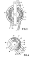
- the other side wall 10 of the battery holder is provided with a carbon track 11 and a contact track 11A, which tracks are arranged as flat rings around an axis of rotation 12. Electrical slip contact 13 and 13A slide along the carbon track 11' and the contact track 11A.
- the contact track 11A consists of a vacuum-deposited metallic layer, which is galvanically connected to the carbon track.
- the potentiometer thus formed is included in the electrical circuit of an amplifier, not shown, with which every hearing aid is equipped.
- each side wall 6 and 10 On the periphery of each side wall 6 and 10 a number of recesses 14 are formed, which are regularly spaced over the circumference. Six of said recesses correspond to a discrete position of the potentiometer or volume control. Furthermore, there has been provided a stop cam 17 on the periphery, which cam corresponds to the initial position.
- the amplifier When the battery holder 1 is rotated, the amplifier is switched on first of all by means of a switch (not shown). Subsequently, the gain is increased depending of course on the position of the slip contact 13 on the carbon track 11, i.e. the position of the volume control.
- the battery holder 1 is to be rotated against a resilient force.
- this is achieved by providing the frame 2 with a radial cylindrical recess, which receives a helical spring 15 ( Figure 2).
- the end of the helical spring is provided with a ball 16, which is made to engage with one of the recesses 14 by the helical spring 15 each time that the battery holder 1 is rotated.
- Figure 4 schematically shows a number of contact tracks, which are disposed concentrically relative to each other.
- the contact tracks consist of thin copper conductors, which are arranged on a flat base. This base may be mounting plate for all electronic components, which mainly belong to the audio amplifier.
- For mounting said contact tracks and electronic components use can be made of the so-called "thick-film" technique, the conductors - including the contact tracks - being printed on a kapton foil and the various electronic components mainly taking the form of integrated semiconductors.
- the contact tracks may also be disposed on a side wall - for example side wall 10 in Figures 1-3.
- the slip contacts which co-operate with the contact tracks, are connected to one of the side walls of the battery holder. By rotation of said holder the position of the slip contacts on the contact tracks is changed.
- the contact tracks form part of three concentric rings.
- the outer ring 40 is provided with an uninterrupted contact track 41 over on. half.
- the centre ring 42 is provided with two contact tracks 43 and 44 disposed circumferentially one after the other.
- the second track 44 is offset from the contact track 41 by one step in the anti-clockwise direction.
- the first track 43 terminates at the same location as the contact track 41.
- the inner ring 45 has a contact track 46 which extends over a quarter circle which is arranged to terminate at the same location as the contact tracks'41 and 43. All contact tracks are galvanically interconnected.
- slip contacts On the rings a number of slip contacts are disposed, namely a slip contact 50 on the ring 40, slip contacts 51 and 53 on the ring 42; slip contact 52 on the ring 45.
- the slip contacts are each arranged one after the other in the numerical sequence in the anti-clockwise direction; the mutual distance corresponds to one step.
- the slip contacts 50-53 retain their position relative to each other.
- Each slip contact is connected to an appropriate resistor.
- one or more slip contacts are electrically ; interconnected in the following positions:
- slip contact 50 is connected to a 500 ⁇ ; 51 to 100 ⁇ ; 52 to 50 ⁇ , and 53 to 20 ⁇ resistor, the positions A-E correspond to the following resistance values: 500 ⁇ , 83 ⁇ , 31 ⁇ , 14 ⁇ and 40 ⁇ .
- FIG. 5 shows an alternative embodiment of the previously described battery holder in accordance with Figures 1-3.
- the carbon track 20 is now situated on the substrate for the associated amplifier, described in the foregoing, and is thus located outside the battery holder 1.
- An electrical slip contact 21 is rigidly connected to said battery holder i.
- the battery holder 1 rotates about pin 30 and pivot bearing 31 in the frame 2.
- the battery holder is provided with a sleeve bearing 32, which is disposed around pin 30.
- One end of pin 30 - which serves as an electrical contact for the battery - is connected to a leaf spring 33.
- Leaf spring 33 is secured to the housing 3.
- the sleeve bearing 32 is provided with a latching cam 34, which has a partly helical shape.
- the leaf spring 33 bears against said cam 34 so that the deflection of the leaf spring 33, i.e. the deflection of the pin 30, depends on the rotary position of the battery holder 1.
- a resilient tab 35 is arranged on the inside of the battery holder 1.
- the leafspring 33 In the open position of the battery holder the leafspring 33 is in the extreme position.
- the cam 34 Upon a slight rotation of the battery holder 1 the cam 34 no longer bears against the leaf spring 33 and pin 30 bears against the side of the battery. The battery is then retained between pin 30 and the resilient tab 35, which tab then functions as the other electrical contact.
Landscapes
- Health & Medical Sciences (AREA)
- General Health & Medical Sciences (AREA)
- Neurosurgery (AREA)
- Otolaryngology (AREA)
- Physics & Mathematics (AREA)
- Engineering & Computer Science (AREA)
- Acoustics & Sound (AREA)
- Signal Processing (AREA)
- Battery Mounting, Suspending (AREA)
Abstract
"This invention relates to a hearing aid of the kind which is provided with a cylindrical battery holder.
A hearing aid, in particular a "behind-the-ear" hearing aid, provided with a cylindrical battery holder which in a specific position permits a battery to be inserted radially and is rotatably journalled in a housing the battery holder extending partly outside the outer wall of the housing and being provided with a switch which switches on the associated amplifier upon rotation of the battery holder, which battery holder is coupled to the volume control of the amplifier.
The volume control may comprise a single annular carbon track or a plurality of conductive contact tracks, which tracks may be arranged either on one of the flat side walls of the battery holder or outside said holder.
Description
- Hearing aids are equipped with a volume control for the built-in amplifier. This control generally comprises a rotary potentiometer, which is manually adjustable with a knurled disc which slightly projects from the housing surface of the hearing aid. The person wearing the hearing aid turns this disc until a position is found which corresponds to the desired amplification of the sound to be transmitted.
- In the last decade hearing aids were miniaturised. This resulted in hearing aids which are worn behind the ear, that is, the so-called "behind-the-ear" type hearing aid; the shape being adapted to that of the earshell and the size being crescent-shape so that this type of hearing aid can be situated almost completely behind the earshell. For such an aid it is of importance that the essential components, such as microphone, receiver, amplifier, battery for the power supply and volume control are very small. In this respect it is also of importance, that the hearing aid has a minimum number of projecting elements.
- The invention relates to a hearing aid, in particular a "behind-the-ear" hearing aid, provided with a cylindrical battery holder, which in a certain position enables a battery to be inserted radially and is rotatably journalled in a housing, said battery holder extending partly outside the outer wall of the housing and being provided with a switch, which switches on the associated amplifier upon rotation of the battery holder.
- Such a hearing aid is for example known from Austrian Patent Specification 278,933.
- The invention is based on the principle of combining the functions of battery holder and volume control. According to the present invention there is provided a hearing aid of the aforesaid kind and which is suitable for use by being worn behind the ear by the user is provided with a cylindrical battery holder, which enables a battery to be inserted radially which the holder is in one position and which is rotatably journalled in a housing, said battery holder extending partly outside the outer wall of the housing, and being provided with a switch which switches on an associated amplifier upon rotation of the battery holder, characterized in that the battery holder is coupled to a volume control of the amplifier.
- By rotating the cylindrical battery holder the amplifier volume is also controlled.
- In one embodiment of the invention the volume control comprises at least one flat and at least partly annular contact track with a cooperating slip contact springs
- Obviously, the contact track is then included in the electrical circuit of the amplifier.
- In a further embodiment the volume control is provided with a single annular contact track, which takes the form of a carbon track. This enables the volume of sound to be controlled continuously.
- In another embodiment the volume control comprises a plurality of concentrically disposed flat, partly annular, contact tracks, each contact track being connected to an associated resistor. The contact tracks then consist of thin metal electrically conducting"strips, which are disposed on a flat insulating base.
- The location of the concentric contact tracks relative to each other permits the gain to be controlled in steps.
- The contact tracks may form part of the battery holder or to be located outside the battery holder. In the first-mentioned case they are arranged on the outside of one of the flat side walls.
- In the other case it is desirable to arrange each contact track on a substrate which is intended for the amplifier. In this respect substrate is to be understood to mean the supporting body for the various electronic elements forming the amplifier. A kapton foil or a ceramic plate, accommodating printed circuitry and the amplifier in the form of an integrated semiconductor device, may for example be used as substrate.
- In a satisfactorily performing hearing aid, the battery holder being provided with a circumferential rim with a plurality of recesses, which cooperate with a resilient latching means, a small number of said recesses are regularly spaced over the circumference, a number of consecutive recesses corresponding to a specific setting of the amplifier sensitivity and the latching means comprising a helical spring enclosed in the housing, which spring urges a ball against the rim or into the recesses.
- The circumference may for example be provided with 12 recesses, of which for example 6 recesses can each produce a difference in sensitivity of 5 dB. The person wearing the hearing aid can then easily adjust the sensitivity of the hearing aid by counting the number of "clicks".
- In order to retain the battery, which is also cy7 lindrical, in the battery holder a flat side wall of the battery holder, in order to form a resilient tab, is provided with two incisions which extend inwards from the insertion opening, the tab being provided with a battery-retaining cam over at least a part of the width of said tab on the battery side and near the circumference.
- The battery can be retained in a different manner in an embodiment of the invention in which the battery holder is rotatable about a pin on one side and via a pivot bearing on the other side. the pin serving as an electrical contact and being urged awards by a leaf spring which is rigidly connected to said pin and which is secured to the housing, whilst around the pin the battery holder is provided with a partly helical latching cam which cooperates with the leaf spring, the electrical connection between the pin and the battery being interrupted in the open position of the battery holder.
- Certain embodiments of the invention will now be described in more detail with reference to the accompanying drawing, in which:
- Figures 1-3 show a battery holder for a hearing aid in accordance with the invention, provided with a carbon- track potentiometer, wherein
- Fig. 1 is a cross-sectional view,
- Fig. 2 is a side view of Figure 1
- Fig. 2a is a cross-section of the tab, taken on the line A-A in Fig. 2,
- Fig. 3 is a different side view of Figure 1,
- Fig. 4 represents a diagram of a number of concentrically arranged contact tracks,
- Fig. 5 shows a cross-sectional view of an alternative arrangement for a number of contact tracks, and
- Fig. 6 shows a cross-sectional view of a further embodiment with battery-retaining means.
- Figures 1-3 show a battery holder, which battery holder is particularly suitable for incorporation in a so-called "behind-the-ear" hearing aid. In view of the overall dimensions of this type of hearing aid such a battery holder should have very small dimensions, although, it is still desirable for the battery holder to be of such a dimension and shape that it can conveniently be operated by hand.
- The battery holder 1 has a flat cylindrical shape and is manufactured from a thin-walled plastics material. The battery holder is journalled in a
frame 2, which belongs to thehousing 3. This housing comprises two precisely engaging shell sections. At the top thehousing 3 has anoblong opening 4, so that a part of the battery holder 1 projects from the outer surface of the housing, as a result of which approximately 1200 of the battery holder circumference is available for manual control. - The battery holder 1 is provided with a
U-shaped cavity 5, whose width substantially corresponds to that of theopening 4. This cavity serves for accommodating a flat cylindrical battery. One of theside walls 6 of the battery holder 1 is provided with atab 7, which extends in the direction of the insertion opening and which is formed by means of twoincisions 8. On the battery side and near the end of the tab, this tab is provided with acam 9 over at least part of its full width, which cam has the shape of a sawtooth which slopes upwards towards the axis of rotation of the holder. When a battery is inserted into thecavity 5 thecam 9 slides along one of the flat side walls of the battery and owing to the resilient force of thetab 7 thecam 9 snaps behind the battery in theend position 1A of the battery, so that the battery is latched in position. - The
other side wall 10 of the battery holder is provided with acarbon track 11 and acontact track 11A, which tracks are arranged as flat rings around an axis ofrotation 12.Electrical slip contact contact track 11A. Thecontact track 11A consists of a vacuum-deposited metallic layer, which is galvanically connected to the carbon track. The potentiometer thus formed is included in the electrical circuit of an amplifier, not shown, with which every hearing aid is equipped. - On the periphery of each
side wall 6 and 10 a number ofrecesses 14 are formed, which are regularly spaced over the circumference. Six of said recesses correspond to a discrete position of the potentiometer or volume control. Furthermore, there has been provided astop cam 17 on the periphery, which cam corresponds to the initial position. When the battery holder 1 is rotated, the amplifier is switched on first of all by means of a switch (not shown). Subsequently, the gain is increased depending of course on the position of theslip contact 13 on thecarbon track 11, i.e. the position of the volume control. - For the person wearing the hearing aid it is convenient if the battery holder 1 is to be rotated against a resilient force. In the present example this is achieved by providing the
frame 2 with a radial cylindrical recess, which receives a helical spring 15 (Figure 2). The end of the helical spring is provided with aball 16, which is made to engage with one of therecesses 14 by thehelical spring 15 each time that the battery holder 1 is rotated. - This is accompanied by a clicking sound so that the person wearing the hearing aid can adjust the aid to a desired sound level by simply counting the numbers of "clicks".
- Between two
adjacent recesses 14 the sound level varies by.a factor of 5 dB. - Figure 4 schematically shows a number of contact tracks, which are disposed concentrically relative to each other. The contact tracks consist of thin copper conductors, which are arranged on a flat base. This base may be mounting plate for all electronic components, which mainly belong to the audio amplifier. For mounting said contact tracks and electronic components use can be made of the so-called "thick-film" technique, the conductors - including the contact tracks - being printed on a kapton foil and the various electronic components mainly taking the form of integrated semiconductors.
- However, the contact tracks may also be disposed on a side wall - for
example side wall 10 in Figures 1-3. - In the first-mentioned case the slip contacts, which co-operate with the contact tracks, are connected to one of the side walls of the battery holder. By rotation of said holder the position of the slip contacts on the contact tracks is changed.
- In the second case the slip contacts remain stationary and the contact tracks are rotated.
- The contact tracks form part of three concentric rings. The
outer ring 40 is provided with anuninterrupted contact track 41 over on. half. Thecentre ring 42 is provided with twocontact tracks second track 44 is offset from thecontact track 41 by one step in the anti-clockwise direction. Thefirst track 43 terminates at the same location as thecontact track 41. Theinner ring 45 has acontact track 46 which extends over a quarter circle which is arranged to terminate at the same location as the contact tracks'41 and 43. All contact tracks are galvanically interconnected. - On the rings a number of slip contacts are disposed, namely a slip contact 50 on the
ring 40,slip contacts ring 42;slip contact 52 on thering 45. - The slip contacts are each arranged one after the other in the numerical sequence in the anti-clockwise direction; the mutual distance corresponds to one step. The slip contacts 50-53 retain their position relative to each other.
- Each slip contact is connected to an appropriate resistor. By rotating the assembly of contact tracks relative to the assembly of slip contacts, one or more slip contacts are electrically;interconnected in the following positions:
- in position A: no slip contacts interconnected
- in position B: 50 to 51,
- in position C: 50, 51 and 52 to each other
- in position D: 50, 52 and 53 to each other
- in position E: 50 to 52.
- If in this order slip contact 50 is connected to a 500Ω ; 51 to 100Ω ; 52 to 50Ω, and 53 to 20Ω resistor, the positions A-E correspond to the following resistance values: 500Ω, 83Ω, 31 Ω, 14Ω and 40Ω.
- If position A is the initial position, the resistance values corresponding to the subsequent positions B-D consecutively decrease, so that the volume of the sound produced by the amplifier and receiver is controlled accordingly.
- Figure 5 shows an alternative embodiment of the previously described battery holder in accordance with Figures 1-3. The
carbon track 20 is now situated on the substrate for the associated amplifier, described in the foregoing, and is thus located outside the battery holder 1. Anelectrical slip contact 21 is rigidly connected to said battery holder i. - In Figure 6 the battery holder 1 rotates about
pin 30 and pivot bearing 31 in theframe 2. For this purpose the battery holder is provided with asleeve bearing 32, which is disposed aroundpin 30. One end of pin 30 - which serves as an electrical contact for the battery - is connected to aleaf spring 33.Leaf spring 33 is secured to thehousing 3. At the front thesleeve bearing 32 is provided with a latching cam 34, which has a partly helical shape. - The
leaf spring 33 bears against said cam 34 so that the deflection of theleaf spring 33, i.e. the deflection of thepin 30, depends on the rotary position of the battery holder 1. - Opposite the pin 30 a
resilient tab 35 is arranged on the inside of the battery holder 1. In the open position of the battery holder theleafspring 33 is in the extreme position. When a battery is inserted into the battery holder 1, the battery slides along (and is clear of) thepin 30. Upon a slight rotation of the battery holder 1 the cam 34 no longer bears against theleaf spring 33 andpin 30 bears against the side of the battery. The battery is then retained betweenpin 30 and theresilient tab 35, which tab then functions as the other electrical contact.
Claims (9)
1. A hearing aid, which is suitable for use by being worn behind the -ear by the user, is provided with a cylindrical battery holder which enables a battery to be inserted radially when the holder is in one position and which is rotatably journalled in a housing, said battery holder extending partly outside the outer wall of the housing, and being provided with a switch which switches on an associated amplifier upon rotation of the battery holder, characterized in that the battery holder is coupled to a volume control of the amplifier.
2. A hearing aid as claimed in Claim 1, characterized in that the volume control comprises at least one flat and at least partly annular contact track with a cooperating slip contact spring.
3. A hearing aid as claimed in Claim 2, characterized in that the volume control is provided with a single annular contact track, which takes the form of a carbon track.
4. A hearing aid as claimed in Claim 2, characterized in that the volume control comprises a plurality of concentrically disposed flat, partly annular, contact tracks, each contact track being connected to an associated resistor.
5. A hearing aid as claimed in any of the Claims 2 to 4, characterized in that each contact track is secured to the outside of one of the flat side walls of the battery holder.
5. A hearing aid as claimed in any of the Claims 2 to 4, characterized in that each contact track is situated on a substrate for the amplifier.
7. A hearing aid as claimed in any of the preceding Claims, the battery holder being provided with a circumferential rim with a plurality of recesses, which cooperate with resilient latching means, is characterized in that a small number of recesses are regularly spaced over the circumference, each recess corresponding to a specific setting of the amplifier sensitivity and the latching means comprising a helical spring enclosed in the housing, which spring urges a ball against the rim or into the recesses.
8. A hearing aid as claimed in any of the preceding Claims, characterized in that, in order to form a resilient tab, a flat side wall of the battery holder is provided with two incisions which extend inwards from the insertion opening, the tab being provided with a battery-retaining cam over at least a part of the width of said tab on the battery side and near the;circumference.
9. A hearing aid as claimed in any of the preceding Claims, characterized in that the battery holder is rotatable about a pin on one side and via a pivot bearing on the other side, the pin serving as an electrical contact is urged inwards by a leaf spring which is rigidly connected to said pin and which is secured to the housing, whilst around the pin the battery holder is provided with a partly helical latching cam which cooperates with the leaf spring, the electrical connection between the pin and the battery being interrupted in the open position of the battery holder.
Applications Claiming Priority (2)
| Application Number | Priority Date | Filing Date | Title |
|---|---|---|---|
| NL7803967 | 1978-04-14 | ||
| NL7803967A NL7803967A (en) | 1978-04-14 | 1978-04-14 | HEARING AID EQUIPPED WITH A CYLINDRICAL BATTERY CASE. |
Publications (1)
| Publication Number | Publication Date |
|---|---|
| EP0004988A1 true EP0004988A1 (en) | 1979-10-31 |
Family
ID=19830652
Family Applications (1)
| Application Number | Title | Priority Date | Filing Date |
|---|---|---|---|
| EP79200162A Withdrawn EP0004988A1 (en) | 1978-04-14 | 1979-04-04 | Hearing-aid with combined potentiometer and cylindrical battery holder |
Country Status (5)
| Country | Link |
|---|---|
| EP (1) | EP0004988A1 (en) |
| JP (1) | JPS54138312A (en) |
| AT (1) | AT361998B (en) |
| DK (1) | DK151279A (en) |
| NL (1) | NL7803967A (en) |
Cited By (5)
| Publication number | Priority date | Publication date | Assignee | Title |
|---|---|---|---|---|
| EP0169990A1 (en) * | 1984-07-09 | 1986-02-05 | AS Audio Service GmbH | Hearing aid |
| EP2091270A1 (en) | 2008-02-12 | 2009-08-19 | Siemens Medical Instruments Pte. Ltd. | Hearing aid with battery compartment |
| WO2009120148A1 (en) * | 2008-03-27 | 2009-10-01 | Siemens Medical Instruments Pte. Ltd. | Hearing aid and battery chamber housing of a hearing aid |
| EP2289250A4 (en) * | 2008-05-12 | 2011-07-20 | Sonic Innovations Inc | Hearing aid housing apparatus |
| US8374368B2 (en) | 2010-03-25 | 2013-02-12 | Sonic Innovations, Inc. | Hearing aid device with a volume control |
Families Citing this family (2)
| Publication number | Priority date | Publication date | Assignee | Title |
|---|---|---|---|---|
| DE3329473A1 (en) * | 1983-08-16 | 1985-03-07 | Toepholm & Westermann, Vaerloese | HOER DEVICE TO WEAR ON THE EAR |
| DE102012211642A1 (en) * | 2012-07-04 | 2013-06-20 | Siemens Medical Instruments Pte. Ltd. | Battery closure device i.e. battery door, for e.g. hearing aid, has bearing arranged at device such that bearing is provided near at geometric center region than at edge area, where device is rotatably mounted at bearing at aid housing |
Citations (4)
| Publication number | Priority date | Publication date | Assignee | Title |
|---|---|---|---|---|
| GB1153195A (en) * | 1966-05-17 | 1969-05-29 | Amplivox Ltd | Improvements in or relating to Battery-Operated Electrical Apparatus |
| US3475566A (en) * | 1966-01-04 | 1969-10-28 | Sonotone Corp | Battery holder and switch for hearing aid unit |
| GB1231113A (en) * | 1969-02-12 | 1971-05-12 | ||
| US3641288A (en) * | 1970-06-01 | 1972-02-08 | Electone Inc | Hearing aid switch |
-
1978
- 1978-04-14 NL NL7803967A patent/NL7803967A/en not_active Application Discontinuation
-
1979
- 1979-04-04 EP EP79200162A patent/EP0004988A1/en not_active Withdrawn
- 1979-04-11 JP JP4410579A patent/JPS54138312A/en active Pending
- 1979-04-11 DK DK151279A patent/DK151279A/en not_active IP Right Cessation
- 1979-04-13 AT AT279579A patent/AT361998B/en not_active IP Right Cessation
Patent Citations (4)
| Publication number | Priority date | Publication date | Assignee | Title |
|---|---|---|---|---|
| US3475566A (en) * | 1966-01-04 | 1969-10-28 | Sonotone Corp | Battery holder and switch for hearing aid unit |
| GB1153195A (en) * | 1966-05-17 | 1969-05-29 | Amplivox Ltd | Improvements in or relating to Battery-Operated Electrical Apparatus |
| GB1231113A (en) * | 1969-02-12 | 1971-05-12 | ||
| US3641288A (en) * | 1970-06-01 | 1972-02-08 | Electone Inc | Hearing aid switch |
Cited By (7)
| Publication number | Priority date | Publication date | Assignee | Title |
|---|---|---|---|---|
| EP0169990A1 (en) * | 1984-07-09 | 1986-02-05 | AS Audio Service GmbH | Hearing aid |
| EP2091270A1 (en) | 2008-02-12 | 2009-08-19 | Siemens Medical Instruments Pte. Ltd. | Hearing aid with battery compartment |
| US8194903B2 (en) | 2008-02-12 | 2012-06-05 | Siemens Medical Instruments Pte. Ltd. | Hearing apparatus with battery compartment locking |
| WO2009120148A1 (en) * | 2008-03-27 | 2009-10-01 | Siemens Medical Instruments Pte. Ltd. | Hearing aid and battery chamber housing of a hearing aid |
| EP2289250A4 (en) * | 2008-05-12 | 2011-07-20 | Sonic Innovations Inc | Hearing aid housing apparatus |
| US8363869B2 (en) | 2008-05-12 | 2013-01-29 | Sonic Innovations, Inc. | Hearing aid housing apparatus |
| US8374368B2 (en) | 2010-03-25 | 2013-02-12 | Sonic Innovations, Inc. | Hearing aid device with a volume control |
Also Published As
| Publication number | Publication date |
|---|---|
| ATA279579A (en) | 1980-09-15 |
| JPS54138312A (en) | 1979-10-26 |
| AT361998B (en) | 1981-04-10 |
| NL7803967A (en) | 1979-10-16 |
| DK151279A (en) | 1979-10-15 |
Similar Documents
| Publication | Publication Date | Title |
|---|---|---|
| US6853290B2 (en) | Switch/volume control assembly | |
| US6974921B2 (en) | Combined roller and push switch assembly | |
| US2632830A (en) | Indexed control | |
| EP0004988A1 (en) | Hearing-aid with combined potentiometer and cylindrical battery holder | |
| US2329949A (en) | Rheostat device | |
| US6275140B1 (en) | Rotary variable resistor | |
| US4184140A (en) | Two-piece trimming potentiometer | |
| US2909749A (en) | Electrical control instrumentality | |
| US4114131A (en) | Variable resistor | |
| WO2009120148A1 (en) | Hearing aid and battery chamber housing of a hearing aid | |
| US3629780A (en) | Variable resistance control and switch with common operating member | |
| US4035758A (en) | Adjustable variable resistance control system | |
| US4306216A (en) | Variable resistor with click mechanism | |
| US3389364A (en) | Electrical control having a nonceramic base and ceramic substrate supported cermet resistance film supported thereon | |
| US4109230A (en) | Compact electrical control | |
| US3684830A (en) | Amplifier mounted on rotor of gain control device | |
| US1356634A (en) | Rheostat for telephonic instruments | |
| US5157371A (en) | Potentiometer retention mechanism and method of mounting | |
| US5095298A (en) | Surface mount variable resistor with insert-molded slider | |
| US2810809A (en) | Variable resistor with improved housing cover securement | |
| US2899662A (en) | High voltage variable resistor | |
| JP2000260608A (en) | Variable resistor and method for manufacturing resistive element substrate used therein | |
| US1920217A (en) | Rheostat | |
| US2852644A (en) | Potentiometers | |
| US2939097A (en) | Variable resistance device |
Legal Events
| Date | Code | Title | Description |
|---|---|---|---|
| PUAI | Public reference made under article 153(3) epc to a published international application that has entered the european phase |
Free format text: ORIGINAL CODE: 0009012 |
|
| AK | Designated contracting states |
Designated state(s): DE FR GB NL |
|
| 17P | Request for examination filed | ||
| STAA | Information on the status of an ep patent application or granted ep patent |
Free format text: STATUS: THE APPLICATION IS DEEMED TO BE WITHDRAWN |
|
| 18D | Application deemed to be withdrawn |
Effective date: 19811123 |
|
| RIN1 | Information on inventor provided before grant (corrected) |
Inventor name: COEHORST, ROBERT FRANCOIS |