EP0004876B1 - Heat exchanger tube guide and extractor tool therefor - Google Patents
Heat exchanger tube guide and extractor tool therefor Download PDFInfo
- Publication number
- EP0004876B1 EP0004876B1 EP79100880A EP79100880A EP0004876B1 EP 0004876 B1 EP0004876 B1 EP 0004876B1 EP 79100880 A EP79100880 A EP 79100880A EP 79100880 A EP79100880 A EP 79100880A EP 0004876 B1 EP0004876 B1 EP 0004876B1
- Authority
- EP
- European Patent Office
- Prior art keywords
- tube
- guide
- tip
- hooks
- tool
- Prior art date
- Legal status (The legal status is an assumption and is not a legal conclusion. Google has not performed a legal analysis and makes no representation as to the accuracy of the status listed.)
- Expired
Links
Images


Classifications
-
- B—PERFORMING OPERATIONS; TRANSPORTING
- B23—MACHINE TOOLS; METAL-WORKING NOT OTHERWISE PROVIDED FOR
- B23P—METAL-WORKING NOT OTHERWISE PROVIDED FOR; COMBINED OPERATIONS; UNIVERSAL MACHINE TOOLS
- B23P19/00—Machines for simply fitting together or separating metal parts or objects, or metal and non-metal parts, whether or not involving some deformation; Tools or devices therefor so far as not provided for in other classes
- B23P19/02—Machines for simply fitting together or separating metal parts or objects, or metal and non-metal parts, whether or not involving some deformation; Tools or devices therefor so far as not provided for in other classes for connecting objects by press fit or for detaching same
- B23P19/025—For detaching only
-
- Y—GENERAL TAGGING OF NEW TECHNOLOGICAL DEVELOPMENTS; GENERAL TAGGING OF CROSS-SECTIONAL TECHNOLOGIES SPANNING OVER SEVERAL SECTIONS OF THE IPC; TECHNICAL SUBJECTS COVERED BY FORMER USPC CROSS-REFERENCE ART COLLECTIONS [XRACs] AND DIGESTS
- Y10—TECHNICAL SUBJECTS COVERED BY FORMER USPC
- Y10T—TECHNICAL SUBJECTS COVERED BY FORMER US CLASSIFICATION
- Y10T29/00—Metal working
- Y10T29/53—Means to assemble or disassemble
- Y10T29/53113—Heat exchanger
-
- Y—GENERAL TAGGING OF NEW TECHNOLOGICAL DEVELOPMENTS; GENERAL TAGGING OF CROSS-SECTIONAL TECHNOLOGIES SPANNING OVER SEVERAL SECTIONS OF THE IPC; TECHNICAL SUBJECTS COVERED BY FORMER USPC CROSS-REFERENCE ART COLLECTIONS [XRACs] AND DIGESTS
- Y10—TECHNICAL SUBJECTS COVERED BY FORMER USPC
- Y10T—TECHNICAL SUBJECTS COVERED BY FORMER US CLASSIFICATION
- Y10T29/00—Metal working
- Y10T29/53—Means to assemble or disassemble
- Y10T29/53987—Tube, sleeve or ferrule
-
- Y—GENERAL TAGGING OF NEW TECHNOLOGICAL DEVELOPMENTS; GENERAL TAGGING OF CROSS-SECTIONAL TECHNOLOGIES SPANNING OVER SEVERAL SECTIONS OF THE IPC; TECHNICAL SUBJECTS COVERED BY FORMER USPC CROSS-REFERENCE ART COLLECTIONS [XRACs] AND DIGESTS
- Y10—TECHNICAL SUBJECTS COVERED BY FORMER USPC
- Y10T—TECHNICAL SUBJECTS COVERED BY FORMER US CLASSIFICATION
- Y10T29/00—Metal working
- Y10T29/53—Means to assemble or disassemble
- Y10T29/53991—Work gripper, anvil, or element
Definitions
- the present invention relates to a combination tube guide and extractor tool.
- the guide permits proper positioning of heat exchanger tubes when being inserted into a steam generator and the tool permits extraction of the guide once the tube is properly disposed. More particularly, this invention relates to such a tube guide and extractor tool for automatic remote engagement therebetween and which become readily disengaged once the tube guide is extracted from the tube.
- Conical-nosed tube guides releasably retained in the leading opening of replacement heat exchanger tubes to guide the tubes through aligned apertures in a series of support plates and ultimately into proper position within openings of a tube sheet of a steam generator are well known in the art. Also, it is known to retain the guides within the tube with bristles projecting from a central stem in a spiral configuration with the outer diameter of the spiral being larger than the inner diameter of the tube for frictional engagement therebetween.
- the guide was readily manually extracted by a workman in the channel head of the generator by merely gripping the tube guide with a plier or like tool.
- the present invention resides in a tube guide and guide pulling arrangement for guiding tubes into apertures through the tube sheet of a steam generator including a tool for extracting said guide once said tube is properly positioned, said arrangement including a tube guide having a generally conical leading end and a cylindrical trailing end adapted to be disposed within the front ends of a tube, said leading end projecting outwardly from said tube to guide said tube through said apertures, and means for releasably retaining said guide within the front end of a tube characterized in that the leading end of said tube guide has a generally conical tip with a stem portion of reduced cross section between the tip and the trailing end the rear end of said tip forming an annular shoulder having an inclined surface and that said tool comprises an extracting member pivotally supported on a tool-holder arm and normally biased into position for engagement with said tip said extracting member having a hook portion with a notch to thereby define a pair of spaced, identical configured hooks defining together an angled surface corresponding to the inclined surface of said
- a portion of the channel head of a steam generator comprising a portion of the tube sheet 12 and a portion of the bottom wall 14.
- the tube sheet has a plurality of openings 16 therethrough in a particular pattern for receiving the open ends of a typical "U"-shaped heat exchanger tube 18.
- the tubes 18 are lowered into position in the tube sheet 12 with the ends thereof first passing through aligned openings in a series of vertically spaced tube support plates (not shown).
- a tube guide on the end of each such tube it is also well known to attach a tube guide on the end of each such tube.
- tube guides are conical or bullet-nosed; however, according to an embodiment of the present invention, the tube guide 20 comprises an initial cylindrical portion 22, sized to closely fit within the internal diameter of the tube 18 and terminating at its lowermost end in an outwardly stepped configuration providing an annular shoulder 24 for abutment with the free end of the tube 18.
- the diameter of the portion of the guide defining the shoulder and the outer diameter of the tube coincide to provide a generally smooth transition therebetween to prevent the tube from catching on the support plates or the tube sheet.
- the tube guide is tapered downwardly inwardly from the shoulder defining portion 24 at a relatively shallow angle (i.e., on the order of 12°) to form an elongated frustoconical portion 26 terminating in a downwardly extending cylindrical stem portion 28.
- An outwardly stepped portion 30 having first and second tapered portions 31, 32 respectively, form the tip of the guide. It will be noted that the annular surface 34 formed by the outward stepped tip 30 is chamfered so as to be slightly angled downwardly outwardly for a purpose to be described.
- the guide 20 is releasably retained within the tube 18 by any well-known means such as a twisted wire stem 36 extending from the cylindrical portion 22 and having a spiraling row of bristles 38 extending outwardly therefrom to frictionally engage the inner wall of the tube 18.
- An extractor tool 40 is mounted on the distal end of an extension 42 mounted on a tool holder arm 44.
- the tool holder arm is movable both horizontally and vertically to position and move the tool as desired to accomplish the tool's function.
- Quick release mounting means such as a pair of well-known grip pins 46 (only one being shown) extend through aligned apertures 45, 47 in the extension and the arm, and a pair of indexing pins 48 received in mating indexing bushings 50 (also only one such pin being shown) align and retain the extension 42 for exact repositioning the extension on the arm each time the extension 42 is mounted.
- the extension 42 comprises a bar member 43 extending substantially horizontally and having generally planar opposed upper and lower surfaces.
- the distal end of the bar has an axially extending notch 52, thereby dividing the end into a pair of horizontally spaced parallel extending fingers 54, 56 having generally vertical planar facing walls 58, 60.
- the extracting tool 42 is retained within the notch 52 by a horizontally extending pin 62 passing through aligned apertures in the fingers and an aperture in the tool for pivotally supporting the tool within the notch 52.
- the tool 42 comprises a solid block-like member having a thickness less than the width of the notch 52 so as to be relatively free to pivot therewithin.
- the radially outermost portion of the block defines an upwardly projecting portion 64 terminating at its uppermost end in an inwardly and downwardly projecting hook portion 66.
- the hook portion 66 is also notched as at 67 to define a pair of spaced, identical configured, hook-like projections 68, 70 having an underside or engaging surface 76 extending radially inwardly and tapered slightly downwardly.
- the upper surface 72 of the hook portion 66 is rounded to provide a downwardly, inwardly extending camming surface 74 which joins the underside 76 of the hook at the radially innermost point 78.
- the upper surface of the block slants donwardly-inwardly from subadjacent the hook portion 66 to terminate in a generally- horizontally extending shelf member 82 projecting in a spaced relationship over the upper surface of the extension 42.
- Shelf 82 has a threaded aperture 84 therethrough with a machine screw 86 received therein and extending into abutting engagement with the upper surface of the extension 42 whereby adjustment of the screw pivots the block about the pin 62 to the desired position.
- a lower shelf member 88 extends from the block in spaced relationship subadjacent the lower surface of the extension.
- the pin 62 on which the block pivots is disposed closely adjacent the outermost side of the block and that, due to the configuration of the block, the weight thereof is so disposed as to normally urge counterclockwise rotation (as viewed in Figure 1) of the block about the pin 62. In the normal position this causes the screw 86 to abut the upper surface of the extension and support the block. Further, it should be pointed out that when the adjusting screw 86 is at the proper extension, a vertical line from the axis of the pin 62 intersects the hook 66 closely adjacent the hook point 78, with a portion of the point 78 extending slightly radially inwardly beyond such vertical line.
- the tool 40 is properly positioned beneath the guide which extends from the tube in the tube sheet.
- the axis of the tube 18 and guide 20 should coincide with the vertical line from the axis of the pin 62 and should also bisect the hook notch 67.
- elevation of the tool causes the rounded upper surface 72 thereof to contact the conical leading surfaces 32, 31 of the guide tip 30 causing the tool to rock clockwise about pin 62 to permit the hook portion 66 to pass over the guide tip 30.
- the weight of the tool 40 causes it to rock counterclockwise.
- the outer diameter of the guide tip 30 abuts the inner wall of the upwardly projecting portion 64 and the hook tip 78 extend on opposite sides of and directly over the annular surface 34 of the guide to engage this surface radially inwardly of the vertical axis.
- the hook notch 67 is sufficiently large for the cylindrical stem portion 28 of the guide to be received therein and the hook tip 78 of each finger of the hook contact the surface 34 not at diametrically opposed positions but, as previously stated inwardly beyond the axis of the guide.
- Such point of engagement in conjunction with the angled surface of the annular surface 34, requires the hook tips 78 be raised to become disengaged from the guide tip 30.
- a coil spring can be disposed and retained between the bottom shelf 88 and the bottom surface of the extension to bias the tool into the counterclockwise position shown.
Landscapes
- Engineering & Computer Science (AREA)
- Mechanical Engineering (AREA)
- Hand Tools For Fitting Together And Separating, Or Other Hand Tools (AREA)
- Dental Tools And Instruments Or Auxiliary Dental Instruments (AREA)
- Automatic Assembly (AREA)
- Heat-Exchange Devices With Radiators And Conduit Assemblies (AREA)
- Treatment Of Fiber Materials (AREA)
Description
- The present invention relates to a combination tube guide and extractor tool. The guide permits proper positioning of heat exchanger tubes when being inserted into a steam generator and the tool permits extraction of the guide once the tube is properly disposed. More particularly, this invention relates to such a tube guide and extractor tool for automatic remote engagement therebetween and which become readily disengaged once the tube guide is extracted from the tube.
- Conical-nosed tube guides, releasably retained in the leading opening of replacement heat exchanger tubes to guide the tubes through aligned apertures in a series of support plates and ultimately into proper position within openings of a tube sheet of a steam generator are well known in the art. Also, it is known to retain the guides within the tube with bristles projecting from a central stem in a spiral configuration with the outer diameter of the spiral being larger than the inner diameter of the tube for frictional engagement therebetween. Thus, upon the tube being positioned within the tube sheet and the tube guide projecting therefrom below the tube sheet, the guide was readily manually extracted by a workman in the channel head of the generator by merely gripping the tube guide with a plier or like tool.
- However in the radioactive environment of the channel head of a nuclear steam generator it is desirable to have any repair or replacement operation to the steam generator accomplished entirely from a remotely operated mechanism which does not require a workman to be within the channel head.
- Thus, it is the principal object of the present invention to provide a tube guide and tool that will automatically properly engage the tube guides for extraction of the guides from the tube and, upon their extraction, immediately and without fail, release the tube guide to clear the tool for engaging the next such guide for extraction.
- With this object in view, the present invention resides in a tube guide and guide pulling arrangement for guiding tubes into apertures through the tube sheet of a steam generator including a tool for extracting said guide once said tube is properly positioned, said arrangement including a tube guide having a generally conical leading end and a cylindrical trailing end adapted to be disposed within the front ends of a tube, said leading end projecting outwardly from said tube to guide said tube through said apertures, and means for releasably retaining said guide within the front end of a tube characterized in that the leading end of said tube guide has a generally conical tip with a stem portion of reduced cross section between the tip and the trailing end the rear end of said tip forming an annular shoulder having an inclined surface and that said tool comprises an extracting member pivotally supported on a tool-holder arm and normally biased into position for engagement with said tip said extracting member having a hook portion with a notch to thereby define a pair of spaced, identical configured hooks defining together an angled surface corresponding to the inclined surface of said annular shoulder, said notch being adapted to receive said stem of said tube guide with said hooks engaging said conical tip such that movement of said tool members toward said tube causes said hooks to pivot said tool member for engagement of said hooks with said tip for extraction of said tube from a tube.
- The invention will become more readily apparent from the following description of a preferred embodiment thereof shown, by way of example only, in the accompanying drawings in which:
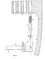
- Figure 1 is a side elevational view of a portion of the channel head of a steam generator showing a tube disposed within a tube sheet and a tube guide and extracting tool, according to the present invention, disposed in engaged position prior to removal of the guide;
- Figure 2 is an enlarged portion of Figure 1 showing the extractor tool in an intermediate position as it is elevated to the position of Figure 1;
- Figure 3 is a cross-sectional view along line III-III of Figure 1; and
- Figure 4 is a view similar to Figure 1 with the guide extracted from the tube.
- In the Figures, a portion of the channel head of a steam generator is shown comprising a portion of the
tube sheet 12 and a portion of thebottom wall 14. The tube sheet has a plurality ofopenings 16 therethrough in a particular pattern for receiving the open ends of a typical "U"-shapedheat exchanger tube 18. As is well known in the art, thetubes 18 are lowered into position in thetube sheet 12 with the ends thereof first passing through aligned openings in a series of vertically spaced tube support plates (not shown). To assist in guiding the blunt open end of each tube through the aligned openings and into theopenings 16 of thetube sheet 12 it is also well known to attach a tube guide on the end of each such tube. For the most part, tube guides are conical or bullet-nosed; however, according to an embodiment of the present invention, thetube guide 20 comprises an initial cylindrical portion 22, sized to closely fit within the internal diameter of thetube 18 and terminating at its lowermost end in an outwardly stepped configuration providing anannular shoulder 24 for abutment with the free end of thetube 18. The diameter of the portion of the guide defining the shoulder and the outer diameter of the tube coincide to provide a generally smooth transition therebetween to prevent the tube from catching on the support plates or the tube sheet. The tube guide is tapered downwardly inwardly from theshoulder defining portion 24 at a relatively shallow angle (i.e., on the order of 12°) to form an elongatedfrustoconical portion 26 terminating in a downwardly extendingcylindrical stem portion 28. An outwardly steppedportion 30 having first and second taperedportions annular surface 34 formed by the outward steppedtip 30 is chamfered so as to be slightly angled downwardly outwardly for a purpose to be described. - The
guide 20 is releasably retained within thetube 18 by any well-known means such as atwisted wire stem 36 extending from the cylindrical portion 22 and having a spiraling row ofbristles 38 extending outwardly therefrom to frictionally engage the inner wall of thetube 18. - An
extractor tool 40 is mounted on the distal end of anextension 42 mounted on atool holder arm 44. (The tool holder arm, is movable both horizontally and vertically to position and move the tool as desired to accomplish the tool's function.) Quick release mounting means such as a pair of well-known grip pins 46 (only one being shown) extend throughaligned apertures pins 48 received in mating indexing bushings 50 (also only one such pin being shown) align and retain theextension 42 for exact repositioning the extension on the arm each time theextension 42 is mounted. Theextension 42 comprises abar member 43 extending substantially horizontally and having generally planar opposed upper and lower surfaces. The distal end of the bar, as more clearly shown in Figure 3, has an axially extendingnotch 52, thereby dividing the end into a pair of horizontally spaced parallel extendingfingers walls 58, 60. The extractingtool 42 is retained within thenotch 52 by a horizontally extendingpin 62 passing through aligned apertures in the fingers and an aperture in the tool for pivotally supporting the tool within thenotch 52. Thetool 42 comprises a solid block-like member having a thickness less than the width of thenotch 52 so as to be relatively free to pivot therewithin. The radially outermost portion of the block defines an upwardly projectingportion 64 terminating at its uppermost end in an inwardly and downwardly projectinghook portion 66. As more clearly seen in Figure 3, thehook portion 66 is also notched as at 67 to define a pair of spaced, identical configured, hook-like projections engaging surface 76 extending radially inwardly and tapered slightly downwardly. - The
upper surface 72 of thehook portion 66 is rounded to provide a downwardly, inwardly extending camming surface 74 which joins theunderside 76 of the hook at the radiallyinnermost point 78. - The upper surface of the block slants donwardly-inwardly from subadjacent the
hook portion 66 to terminate in a generally- horizontally extendingshelf member 82 projecting in a spaced relationship over the upper surface of theextension 42. Shelf 82 has a threadedaperture 84 therethrough with amachine screw 86 received therein and extending into abutting engagement with the upper surface of theextension 42 whereby adjustment of the screw pivots the block about thepin 62 to the desired position. Alower shelf member 88 extends from the block in spaced relationship subadjacent the lower surface of the extension. - It is noted that the
pin 62 on which the block pivots is disposed closely adjacent the outermost side of the block and that, due to the configuration of the block, the weight thereof is so disposed as to normally urge counterclockwise rotation (as viewed in Figure 1) of the block about thepin 62. In the normal position this causes thescrew 86 to abut the upper surface of the extension and support the block. Further, it should be pointed out that when the adjustingscrew 86 is at the proper extension, a vertical line from the axis of thepin 62 intersects thehook 66 closely adjacent thehook point 78, with a portion of thepoint 78 extending slightly radially inwardly beyond such vertical line. - In operation, the
tool 40 is properly positioned beneath the guide which extends from the tube in the tube sheet. In such position the axis of thetube 18 andguide 20 should coincide with the vertical line from the axis of thepin 62 and should also bisect thehook notch 67. In this position, elevation of the tool causes the roundedupper surface 72 thereof to contact the conical leadingsurfaces guide tip 30 causing the tool to rock clockwise aboutpin 62 to permit thehook portion 66 to pass over theguide tip 30. Once thehook tip 78 is above theannular surface 34 of the guide, the weight of thetool 40 causes it to rock counterclockwise. Thus, as more clearly seen in Figure 3, the outer diameter of theguide tip 30 abuts the inner wall of the upwardly projectingportion 64 and thehook tip 78 extend on opposite sides of and directly over theannular surface 34 of the guide to engage this surface radially inwardly of the vertical axis. It is further noted that thehook notch 67 is sufficiently large for thecylindrical stem portion 28 of the guide to be received therein and thehook tip 78 of each finger of the hook contact thesurface 34 not at diametrically opposed positions but, as previously stated inwardly beyond the axis of the guide. Such point of engagement, in conjunction with the angled surface of theannular surface 34, requires thehook tips 78 be raised to become disengaged from theguide tip 30. Because of engagement of the hook beyond the axis of the guide, and because the engagement is on the angled or chamfered surface, the hook tip engages the surfaces at a lower elevation then the elevation of the angled surface immediately behind such position. Thus, any movement of the tool radially outwardly that might cause disengagement, would also require the tool to be moved upwardly to pass over the elevated surface. Thus, as all extracting motion is downwardly and the hook is prevented from such upward movement, the hook and guide cannot become disengaged during the extraction process. - Once the
guide 20 has been freed from the tube it is free to fall from the tool as there is no wedging or clamping action therebetween. In this instance, the guide is free to fall to the bottom of the channel head for subsequent removal. - As an alternative method to relying solely on the weight of the tool to pivot it counterclockwise about the
pin 62 to effect engagement with theguide 20, a coil spring can be disposed and retained between thebottom shelf 88 and the bottom surface of the extension to bias the tool into the counterclockwise position shown.
Claims (3)
Applications Claiming Priority (2)
| Application Number | Priority Date | Filing Date | Title |
|---|---|---|---|
| US898348 | 1978-04-21 | ||
| US05/898,348 US4180902A (en) | 1978-04-21 | 1978-04-21 | Heat exchanger tube guide and extractor tool therefor |
Publications (2)
| Publication Number | Publication Date |
|---|---|
| EP0004876A1 EP0004876A1 (en) | 1979-10-31 |
| EP0004876B1 true EP0004876B1 (en) | 1981-12-30 |
Family
ID=25409319
Family Applications (1)
| Application Number | Title | Priority Date | Filing Date |
|---|---|---|---|
| EP79100880A Expired EP0004876B1 (en) | 1978-04-21 | 1979-03-23 | Heat exchanger tube guide and extractor tool therefor |
Country Status (5)
| Country | Link |
|---|---|
| US (1) | US4180902A (en) |
| EP (1) | EP0004876B1 (en) |
| JP (1) | JPS54141902A (en) |
| DE (1) | DE2961644D1 (en) |
| ES (1) | ES257485Y (en) |
Families Citing this family (3)
| Publication number | Priority date | Publication date | Assignee | Title |
|---|---|---|---|---|
| GB2263732B (en) * | 1992-01-22 | 1995-01-25 | Chang Hsing Wen | An extractor unit |
| CN104128906A (en) * | 2014-08-01 | 2014-11-05 | 张家港化工机械股份有限公司 | Guide head penetrating through heat exchange tube |
| CN108127368A (en) * | 2017-11-07 | 2018-06-08 | 武汉船用机械有限责任公司 | The assembly tooling of a kind of hole and axis and assembly method |
Family Cites Families (5)
| Publication number | Priority date | Publication date | Assignee | Title |
|---|---|---|---|---|
| US1536553A (en) * | 1923-01-27 | 1925-05-05 | Enoch C Seale | Roller-bearing-sleeve puller |
| US1567485A (en) * | 1925-06-10 | 1925-12-29 | Zim Mfg Company | Tool for removing spring supports on axles |
| US2275393A (en) * | 1940-10-02 | 1942-03-03 | Snap Grip Products Inc | Tool |
| US3906607A (en) * | 1974-09-05 | 1975-09-23 | Alexei Alexeevich Gusev | Device for relative orientation of parts |
| DE2620406B2 (en) * | 1976-05-08 | 1980-04-03 | Gerhard 4600 Dortmund Hindrichs | Assembly device for pushing the tubes into the tube sheet of large heat exchange systems |
-
1978
- 1978-04-21 US US05/898,348 patent/US4180902A/en not_active Expired - Lifetime
-
1979
- 1979-03-23 EP EP79100880A patent/EP0004876B1/en not_active Expired
- 1979-03-23 DE DE7979100880T patent/DE2961644D1/en not_active Expired
- 1979-04-20 ES ES1979257485U patent/ES257485Y/en not_active Expired
- 1979-04-20 JP JP4812279A patent/JPS54141902A/en active Pending
Also Published As
| Publication number | Publication date |
|---|---|
| ES257485U (en) | 1981-10-16 |
| EP0004876A1 (en) | 1979-10-31 |
| US4180902A (en) | 1980-01-01 |
| JPS54141902A (en) | 1979-11-05 |
| ES257485Y (en) | 1982-05-01 |
| DE2961644D1 (en) | 1982-02-18 |
Similar Documents
| Publication | Publication Date | Title |
|---|---|---|
| US4153981A (en) | Attaching assembly for sheet material | |
| EP0153267A2 (en) | Removal tool for tangless helically coiled insert | |
| US4715636A (en) | Gripper including an exchangeable gripping jaw | |
| CA1165562A (en) | Furnace taphole drilling apparatus and method | |
| GB2135291A (en) | Separating and releasing device for single elements, particularly cups | |
| EP0004876A1 (en) | Heat exchanger tube guide and extractor tool therefor | |
| CA1260630A (en) | Control cluster provided with removable control elements for a nuclear fuel reactor | |
| US5069861A (en) | Apparatus for the remote unscrewing and extraction of an assembly screw | |
| EP0980724A2 (en) | Punch guide assembly | |
| KR820002031B1 (en) | Tube guide extractor tool for steam generator | |
| CA1123584A (en) | Heat exchanger tube guide and extractor tool therefor | |
| US4206543A (en) | Pin insertion tool | |
| US4373247A (en) | Method and device for removing a ring traveller from the ring of a ring-spinning or ring-twisting frame | |
| US4284285A (en) | Self-adjusting rotary chuck | |
| EP0168698A1 (en) | Tube gripper for secondary side tubes of steam generator | |
| JP2002137134A (en) | Tool pot | |
| TW202045826A (en) | Tongue break-off tool and tongue break-off method | |
| US6430790B1 (en) | Boiler tube flared-end segment peeler tool | |
| JPH034323B2 (en) | ||
| CN212497527U (en) | Reactor core thermocouple plugging device | |
| CN223699611U (en) | A tungsten electrode replacement device, a welding robot, and a robotic automated welding system. | |
| US4481982A (en) | Weft pull-back device of a jet weaving loom | |
| KR19990022840U (en) | pot connecting apparatus | |
| EP0212902A2 (en) | Method of removing and replacing locking screws in a nuclear fuel assembly | |
| US4641452A (en) | Apparatus for hooking and possibly baiting of a fishing line |
Legal Events
| Date | Code | Title | Description |
|---|---|---|---|
| PUAI | Public reference made under article 153(3) epc to a published international application that has entered the european phase |
Free format text: ORIGINAL CODE: 0009012 |
|
| AK | Designated contracting states |
Designated state(s): CH DE FR IT SE |
|
| 17P | Request for examination filed | ||
| ITF | It: translation for a ep patent filed | ||
| GRAA | (expected) grant |
Free format text: ORIGINAL CODE: 0009210 |
|
| AK | Designated contracting states |
Designated state(s): CH DE FR IT SE |
|
| REF | Corresponds to: |
Ref document number: 2961644 Country of ref document: DE Date of ref document: 19820218 |
|
| PGFP | Annual fee paid to national office [announced via postgrant information from national office to epo] |
Ref country code: CH Payment date: 19830128 Year of fee payment: 5 |
|
| PGFP | Annual fee paid to national office [announced via postgrant information from national office to epo] |
Ref country code: DE Payment date: 19830129 Year of fee payment: 5 |
|
| PGFP | Annual fee paid to national office [announced via postgrant information from national office to epo] |
Ref country code: SE Payment date: 19830131 Year of fee payment: 5 |
|
| PGFP | Annual fee paid to national office [announced via postgrant information from national office to epo] |
Ref country code: FR Payment date: 19830203 Year of fee payment: 5 |
|
| PG25 | Lapsed in a contracting state [announced via postgrant information from national office to epo] |
Ref country code: SE Effective date: 19840324 |
|
| PG25 | Lapsed in a contracting state [announced via postgrant information from national office to epo] |
Ref country code: CH Effective date: 19840331 |
|
| PG25 | Lapsed in a contracting state [announced via postgrant information from national office to epo] |
Ref country code: FR Free format text: LAPSE BECAUSE OF NON-PAYMENT OF DUE FEES Effective date: 19841130 |
|
| REG | Reference to a national code |
Ref country code: CH Ref legal event code: PL |
|
| PG25 | Lapsed in a contracting state [announced via postgrant information from national office to epo] |
Ref country code: DE Effective date: 19841201 |
|
| REG | Reference to a national code |
Ref country code: FR Ref legal event code: ST |
|
| EUG | Se: european patent has lapsed |
Ref document number: 79100880.8 Effective date: 19850529 |
|
| PLBE | No opposition filed within time limit |
Free format text: ORIGINAL CODE: 0009261 |
|
| STAA | Information on the status of an ep patent application or granted ep patent |
Free format text: STATUS: NO OPPOSITION FILED WITHIN TIME LIMIT |