EP0004419B1 - Method of manufacturing an actuator rod - Google Patents
Method of manufacturing an actuator rod Download PDFInfo
- Publication number
- EP0004419B1 EP0004419B1 EP79300307A EP79300307A EP0004419B1 EP 0004419 B1 EP0004419 B1 EP 0004419B1 EP 79300307 A EP79300307 A EP 79300307A EP 79300307 A EP79300307 A EP 79300307A EP 0004419 B1 EP0004419 B1 EP 0004419B1
- Authority
- EP
- European Patent Office
- Prior art keywords
- rod
- spigot
- tool
- upsetting
- thread
- Prior art date
- Legal status (The legal status is an assumption and is not a legal conclusion. Google has not performed a legal analysis and makes no representation as to the accuracy of the status listed.)
- Expired
Links
- 238000004519 manufacturing process Methods 0.000 title claims description 12
- 238000000034 method Methods 0.000 claims description 11
- 238000005096 rolling process Methods 0.000 claims description 8
- 239000012530 fluid Substances 0.000 description 5
- 229910001209 Low-carbon steel Inorganic materials 0.000 description 4
- 238000003754 machining Methods 0.000 description 4
- 230000000694 effects Effects 0.000 description 3
- 229910000831 Steel Inorganic materials 0.000 description 1
- 230000006978 adaptation Effects 0.000 description 1
- 230000006835 compression Effects 0.000 description 1
- 238000007906 compression Methods 0.000 description 1
- 238000005520 cutting process Methods 0.000 description 1
- 238000005242 forging Methods 0.000 description 1
- 230000000977 initiatory effect Effects 0.000 description 1
- 239000000463 material Substances 0.000 description 1
- 230000000284 resting effect Effects 0.000 description 1
- 239000010959 steel Substances 0.000 description 1
- 239000013589 supplement Substances 0.000 description 1
- 230000009466 transformation Effects 0.000 description 1
Images

Classifications
-
- B—PERFORMING OPERATIONS; TRANSPORTING
- B21—MECHANICAL METAL-WORKING WITHOUT ESSENTIALLY REMOVING MATERIAL; PUNCHING METAL
- B21K—MAKING FORGED OR PRESSED METAL PRODUCTS, e.g. HORSE-SHOES, RIVETS, BOLTS OR WHEELS
- B21K23/00—Making other articles
- B21K23/04—Making other articles flanged articles
-
- B—PERFORMING OPERATIONS; TRANSPORTING
- B21—MECHANICAL METAL-WORKING WITHOUT ESSENTIALLY REMOVING MATERIAL; PUNCHING METAL
- B21J—FORGING; HAMMERING; PRESSING METAL; RIVETING; FORGE FURNACES
- B21J5/00—Methods for forging, hammering, or pressing; Special equipment or accessories therefor
- B21J5/06—Methods for forging, hammering, or pressing; Special equipment or accessories therefor for performing particular operations
- B21J5/08—Upsetting
-
- B—PERFORMING OPERATIONS; TRANSPORTING
- B21—MECHANICAL METAL-WORKING WITHOUT ESSENTIALLY REMOVING MATERIAL; PUNCHING METAL
- B21K—MAKING FORGED OR PRESSED METAL PRODUCTS, e.g. HORSE-SHOES, RIVETS, BOLTS OR WHEELS
- B21K1/00—Making machine elements
- B21K1/76—Making machine elements elements not mentioned in one of the preceding groups
-
- Y—GENERAL TAGGING OF NEW TECHNOLOGICAL DEVELOPMENTS; GENERAL TAGGING OF CROSS-SECTIONAL TECHNOLOGIES SPANNING OVER SEVERAL SECTIONS OF THE IPC; TECHNICAL SUBJECTS COVERED BY FORMER USPC CROSS-REFERENCE ART COLLECTIONS [XRACs] AND DIGESTS
- Y10—TECHNICAL SUBJECTS COVERED BY FORMER USPC
- Y10T—TECHNICAL SUBJECTS COVERED BY FORMER US CLASSIFICATION
- Y10T29/00—Metal working
- Y10T29/49—Method of mechanical manufacture
- Y10T29/49826—Assembling or joining
- Y10T29/49908—Joining by deforming
- Y10T29/49915—Overedge assembling of seated part
-
- Y—GENERAL TAGGING OF NEW TECHNOLOGICAL DEVELOPMENTS; GENERAL TAGGING OF CROSS-SECTIONAL TECHNOLOGIES SPANNING OVER SEVERAL SECTIONS OF THE IPC; TECHNICAL SUBJECTS COVERED BY FORMER USPC CROSS-REFERENCE ART COLLECTIONS [XRACs] AND DIGESTS
- Y10—TECHNICAL SUBJECTS COVERED BY FORMER USPC
- Y10T—TECHNICAL SUBJECTS COVERED BY FORMER US CLASSIFICATION
- Y10T29/00—Metal working
- Y10T29/49—Method of mechanical manufacture
- Y10T29/49826—Assembling or joining
- Y10T29/49908—Joining by deforming
- Y10T29/49938—Radially expanding part in cavity, aperture, or hollow body
-
- Y—GENERAL TAGGING OF NEW TECHNOLOGICAL DEVELOPMENTS; GENERAL TAGGING OF CROSS-SECTIONAL TECHNOLOGIES SPANNING OVER SEVERAL SECTIONS OF THE IPC; TECHNICAL SUBJECTS COVERED BY FORMER USPC CROSS-REFERENCE ART COLLECTIONS [XRACs] AND DIGESTS
- Y10—TECHNICAL SUBJECTS COVERED BY FORMER USPC
- Y10T—TECHNICAL SUBJECTS COVERED BY FORMER US CLASSIFICATION
- Y10T403/00—Joints and connections
- Y10T403/49—Member deformed in situ
Definitions
- This invention relates to actuator rod manufacture and relates especially but not exclusively to the manufacture of actuator rods of vehicle fluid pressure-operable spring brake actuators.
- a fluid pressure-responsive diaphragm which, when pressurised, acts against a push plate mounted on the inward end of a rod extending outwardly. of the actuator.
- the connecting rod thus operates to transmit to vehicle brakes a braking force applied to the rod via the push plate.
- the push plate is usually mounted by riveting or otherwise fixing by means of a spigot at the inward end of the rod and it is necessary not only that the spigot shall be sufficiently robust but also more especially that a sufficiently large annular bearing face for the plate shall be provided laterally of the spigot.
- the diameter of the actuator rod has therefore to be determined by the acceptable size of the threaded part and by the annular area of the rod which is available around the spigot. Upsetting or forging of rods to produce local enhancement of cross sectional area has already been proposed for example in the Specifications of U.S. Patents 1,338,779 and 1,885,648.
- a method of manufacturing an actuator rod the end of which is upset to afford increased area characterised by the steps of forming at one end of the rod a spigot the diameter of which is less than that of the main body of the rod, undercutting of the end part of the rod at the root of the spigot, causing relative rotation to the rod in relation to an upsetting tool to upset the undercut end part of the rod to produce an enlarged surface area of flange around said spigot and mounting a plate on said spigot to abut said enlarged surface area.
- the spigot may be formed by machining and the machining tool may be so angled that the end of the main body of the rod is undercut around the root of the spigot.
- the upsetting of the end of the main body of the rod around the root of the spigot can be achieved by exerting substantial forces between the rod and an upsetting tool mounted coaxially with the rod.
- the upsetting tool may comprise a pair of hardened rollers against which the end of the main body of the rod rollingly bears whilst being rotated.
- this shows a common form of fluid pressure-responsive brake actuator which has been designed to provide the actuating force to operate the road wheel brakes of commercial road vehicles. Nevertheless, such actuators can be employed in other pneumatic actuator applications.
- the housing is formed of two pressed-steel parts, the main body part 1 being provided with mild-steel mounting studs 2 for mounting the actuator to a chassis or frame and the other part comprising an end plate 4 between the rim of which and a corresponding rim of the body part 1, a diaphragm 5 is clamped by a clamping ring 3.
- the actuator is maintained in the unoperated position shown by a return spring 6 under compression between the flat base of the body part 1 and a mild-steel pressure plate 7 riveted on a spigot on the inner end of a mild-steel actuator rod 8.
- the rod 8 has a suitable screw-thread formed over a length of the outward extending end for fitment to a suitable clevis for connection to the brakes or other mechanism to be operated.
- the region contained between the end cap 4 and the diaphragm 5 is provided with an inlet port via a boss 9 which is conveniently concentric with the arrangement.
- an alternative inlet boss 10 is provided and either 9 or 10 may be plugged by a plug 11.
- the housing part 1 is provided with vent apertures such as 12 whereby the righthand side of the diaphragm is always maintained at or near atmospheric pressure.
- the push rod 8 is formed with a spigot, as referred to above, which passes through a central aperture in the pressure plate 7 and is riveted over such as to present a smooth face to the rear side of the diaphragm 5. It is necessary that the diameter of the actuator rod 8 shall be sufficiently large for the spigot to be of sufficient diameter to enable a suitably strong riveting operation to be effected and also to leave a sufficiently large area of the inward end of the rod to bear against the right hand side of the pressure plate 7.
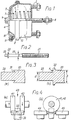
- Fig. 2 there is shown an alternative actuator rod which may be used in place of the actuator rod 8 in the actuator of Fig. 1.
- This actuator rod has a main body diameter D which is appreciably less than the main body diameter of the push rod 8 and the threaded portion on the outward end is rolled to give an equivalent clearing diameter for the thread.
- the inward end is formed like the rod 8 with a spigot denoted by reference 22, the diameter of which is substantially the same as the pre-riveted spigot employed on the rod 8.
- the surface area of the inward end of the main body 20 would provide insufficient bearing surface for a pressure plate such as 7 of Fig. 1 without the formed-up flange 23 formed on it to supplement the available area at the end of the inner end of the main body portion 20.
- the present invention is mainly concerned with the manner of production of mild steel actuator rods such as shown in Fig. 2, and Fig. 3 shows enlarged views of the inner end of a rod of Fig. 2 during the manufacturing process.
- the rod is first taken from a standard machining process which provides the spigot 22 as shown at (a) of Fig. 3, but the machining process is modified to the extent that the cutting tool is angled to undercut the inward end of the main body part at the point 31, at the root of the spigot as shown in (a).
- the inward end of the main body part is up-set to produce a flange such as 32 in Fig. 3(b), whereby the area A presented to a subsequently fitted pressure plate such as 7 of Fig. 1, may be more than twice the area which would otherwise be possible with the diameters (d) and D respectively of the spigot and main body part as shown.
- the transformation of the inner end of the actuator rod from the stage (a) to the stage (b) of Fig. 3, is achievable by employing a roll-swaging head employing a pair of upsetting rollers 41 and 42 mounted co-axially in the body of the head and offering the arrangement co-axially towards the push rod denoted by reference 20 with a pressure which in hydraulic terms may be of the order of up to 2758 x 10 3 Pascals (400 p.s.i.).
- the rod 20 and the roll-swaging head are relatively rotated and since the rollers 41 and 42 fit snugly on either side of the spigot 22, the effect on the shoulder 31 of Fig.
- rollers 41 and 42 are provided freely rotatable with axes at right angles to the common axis of rollers 41 and 42 and so spaced as to determine the outer diameter of the upset flange 32 and prevent feathering of the outer edge thereof. All four rollers are contained within the single roll-swaging head.
- Fig. 5 the plan view shown therein is a downward view upon the bed of a rotating machine which, for convenience, may be regarded as being provided with a pair of rotary bearing stocks 51 and 52.
- the stock 51 carries a thread-rolling die 53 and the stock 52 carries a roll-swaging head 54 employing four rollers as described above with reference to Fig. 4.
- the spindle of the stock 51 is tubular to enable a fixed stop-rod 55 to pass therethrough, being fixed to a back-stop carrier 56 adjustable by a lead screw and handle 57.
- the back-stop carrier is slidable on two stout bars 58 which extend the full length of the machine.
- a thrust cage 59 within which a machine drive pulley 60 is provided coupled to the rotating head-stock 51.
- a similar thrust cage 62 is provided between a fixed hydraulic cylinder 63 and the rotatable end-stock 52 to contain a further drive pulley 64 for driving the roll-swaging head 54.
- the back-stop carrier 56 is provided with an adjustable fixed stop 65 and an hydraulic ram 66, the purpose of which is to provide a starting thrust for the thread-rolling head 53.
- an adjustable overrun detector 67 which on being reached by the carriage of the stock 51, interrupts the supply to the motor (not shown) which drives the pulley 60.
- the hydraulic cylinder 63 which operates as a roll-swaging ram, has an associated pressure-sensing arrangement which interrupts operation of the ram when a predetermined pressure is attained indicating that the resistance is such that the required up- setting of the flange on the inner end of the main body of the actuator rod has been produced.
- the machine operator turns the rotatable stocks 51 and 52 to their most separated positions and inserts the actuator rod 20 in position as shown with the left hand end inserted in the thread-rolling head, the otherwise unsupported part resting in a slidable vice carrier 68.
- This vice carrier permits a small floating clearance having regard to the bars 58 for permitting entry of the spigot on the right hand end of the rod to enter the roll-swaging head.
- the operator starts the motor driving the pulley 60 and energises the hydraulic thread-start cylinder 66.
- the operation of the cylinder 66 produces a deflection of up to an inch before the rotation of the thread-rowing head 53 takes over the drive and leads itself onto the rod for the required distance until the rotary stock reaches an adjustable stop or the detector 67. Attainment of this position can automatically open the die-head and cuts off the drive to the pulley 60. Meanwhile the completion of the stroke of cylinder 66 initiates the operation of the hydraulic ram cylinder 63 and the drive to the pulley 64. The roll-swaging head is thereby automatically led onto the spigot on the actuator rod being formed and the roll-swaging process takes place as described above, with reference to Figs.
- the up-setting of the flange 32 (Fig. 3) on the actuator rod is effected by a roll-swaging head, this may equally be achieved albeit with substantial noise and vibration, by employing a rotating percussive tool in place of the roll-swaging head 54 mounted on the rotatable stock 52.
Landscapes
- Engineering & Computer Science (AREA)
- Mechanical Engineering (AREA)
- Forging (AREA)
Description
- This invention relates to actuator rod manufacture and relates especially but not exclusively to the manufacture of actuator rods of vehicle fluid pressure-operable spring brake actuators.
- In vehicle fluid pressure-operable brake actuators, it is well known to provide a fluid pressure-responsive diaphragm which, when pressurised, acts against a push plate mounted on the inward end of a rod extending outwardly. of the actuator. The connecting rod thus operates to transmit to vehicle brakes a braking force applied to the rod via the push plate. The push plate is usually mounted by riveting or otherwise fixing by means of a spigot at the inward end of the rod and it is necessary not only that the spigot shall be sufficiently robust but also more especially that a sufficiently large annular bearing face for the plate shall be provided laterally of the spigot. Since the outward end of the rod usually has a suitable screw thread cut thereon over a part of its length for the attachment of a clevis or other means for connecting the rod to the brake mechanism, the diameter of the actuator rod has therefore to be determined by the acceptable size of the threaded part and by the annular area of the rod which is available around the spigot. Upsetting or forging of rods to produce local enhancement of cross sectional area has already been proposed for example in the Specifications of U.S. Patents 1,338,779 and 1,885,648.
- According to the present invention, there is provided a method of manufacturing an actuator rod the end of which is upset to afford increased area characterised by the steps of forming at one end of the rod a spigot the diameter of which is less than that of the main body of the rod, undercutting of the end part of the rod at the root of the spigot, causing relative rotation to the rod in relation to an upsetting tool to upset the undercut end part of the rod to produce an enlarged surface area of flange around said spigot and mounting a plate on said spigot to abut said enlarged surface area.
- The spigot may be formed by machining and the machining tool may be so angled that the end of the main body of the rod is undercut around the root of the spigot.
- The upsetting of the end of the main body of the rod around the root of the spigot can be achieved by exerting substantial forces between the rod and an upsetting tool mounted coaxially with the rod.
- The upsetting tool may comprise a pair of hardened rollers against which the end of the main body of the rod rollingly bears whilst being rotated.
- By virtue of the example of the present invention about to be described, wherein on the one hand a rolled thread is provided at the output end of an actuator rod and an upset area is formed at the inner end of the rod surrounding the spigot carrying the push plate, the necessary diameter of the stock material for the rod may be reduced, together with the overall cost of manufacture.
- In order that the invention may be more clearly understood and readily carried into effect, the same will be further described by way of example, with reference to the accompanying drawings of which:-
- Fig. 1 illustrates a fluid pressure-operable brake actuator,
- Fig. 2 illustrates a push rod for such an actuator manufactured in accordance with the present invention,
- Fig. 3 shows enlarged sectional views of the inward end of the push rod before and after roll-swaging to produce the push rod of Fig. 2,
- Fig. 4 illustrates plan and side views at (a) and (b) of the essential parts of a roll-swaging head for use in the manufacture of the push rod, and,
- Fig. 5 illustrates in schematic form, a plan view of an adaptation of a machine tool for manufacturing actuator rods in accordance with a method employing the present invention.
- Referring to Fig. 1, this shows a common form of fluid pressure-responsive brake actuator which has been designed to provide the actuating force to operate the road wheel brakes of commercial road vehicles. Nevertheless, such actuators can be employed in other pneumatic actuator applications.
- The housing is formed of two pressed-steel parts, the main body part 1 being provided with mild-
steel mounting studs 2 for mounting the actuator to a chassis or frame and the other part comprising an end plate 4 between the rim of which and a corresponding rim of the body part 1, a diaphragm 5 is clamped by aclamping ring 3. The actuator is maintained in the unoperated position shown by a return spring 6 under compression between the flat base of the body part 1 and a mild-steel pressure plate 7 riveted on a spigot on the inner end of a mild-steel actuator rod 8. Therod 8 has a suitable screw-thread formed over a length of the outward extending end for fitment to a suitable clevis for connection to the brakes or other mechanism to be operated. The region contained between the end cap 4 and the diaphragm 5 is provided with an inlet port via a boss 9 which is conveniently concentric with the arrangement. In the arrangement shown, analternative inlet boss 10 is provided and either 9 or 10 may be plugged by aplug 11. The housing part 1 is provided with vent apertures such as 12 whereby the righthand side of the diaphragm is always maintained at or near atmospheric pressure. - The
push rod 8 is formed with a spigot, as referred to above, which passes through a central aperture in the pressure plate 7 and is riveted over such as to present a smooth face to the rear side of the diaphragm 5. It is necessary that the diameter of theactuator rod 8 shall be sufficiently large for the spigot to be of sufficient diameter to enable a suitably strong riveting operation to be effected and also to leave a sufficiently large area of the inward end of the rod to bear against the right hand side of the pressure plate 7. In Fig. 2, there is shown an alternative actuator rod which may be used in place of theactuator rod 8 in the actuator of Fig. 1. This actuator rod has a main body diameter D which is appreciably less than the main body diameter of thepush rod 8 and the threaded portion on the outward end is rolled to give an equivalent clearing diameter for the thread. The inward end is formed like therod 8 with a spigot denoted byreference 22, the diameter of which is substantially the same as the pre-riveted spigot employed on therod 8. - With such a diameter of
spigot 22 and the reduced diameter D of themain body part 20 of the rod of Fig. 2, the surface area of the inward end of themain body 20 would provide insufficient bearing surface for a pressure plate such as 7 of Fig. 1 without the formed-upflange 23 formed on it to supplement the available area at the end of the inner end of themain body portion 20. - The present invention is mainly concerned with the manner of production of mild steel actuator rods such as shown in Fig. 2, and Fig. 3 shows enlarged views of the inner end of a rod of Fig. 2 during the manufacturing process. The rod is first taken from a standard machining process which provides the
spigot 22 as shown at (a) of Fig. 3, but the machining process is modified to the extent that the cutting tool is angled to undercut the inward end of the main body part at thepoint 31, at the root of the spigot as shown in (a). By processing in a machine provided with a roll-swaging facility, the inward end of the main body part is up-set to produce a flange such as 32 in Fig. 3(b), whereby the area A presented to a subsequently fitted pressure plate such as 7 of Fig. 1, may be more than twice the area which would otherwise be possible with the diameters (d) and D respectively of the spigot and main body part as shown. - Referring to Fig. 4, the transformation of the inner end of the actuator rod from the stage (a) to the stage (b) of Fig. 3, is achievable by employing a roll-swaging head employing a pair of
upsetting rollers reference 20 with a pressure which in hydraulic terms may be of the order of up to 2758 x 103 Pascals (400 p.s.i.). At the same time, therod 20 and the roll-swaging head are relatively rotated and since therollers spigot 22, the effect on theshoulder 31 of Fig. 3(a) is to up-set the shoulder to produce the flange such as 32. Although not essential to the operation, a further pair of rollers, one of which is denoted byreference 44 and the other of which is denoted byreference 45, more clearly shown in Fig. 4(b), are provided freely rotatable with axes at right angles to the common axis ofrollers upset flange 32 and prevent feathering of the outer edge thereof. All four rollers are contained within the single roll-swaging head. - Referring now to Fig. 5, the plan view shown therein is a downward view upon the bed of a rotating machine which, for convenience, may be regarded as being provided with a pair of rotary bearing
stocks stock 51 carries a thread-rollingdie 53 and thestock 52 carries a roll-swaginghead 54 employing four rollers as described above with reference to Fig. 4. The spindle of thestock 51 is tubular to enable a fixed stop-rod 55 to pass therethrough, being fixed to a back-stop carrier 56 adjustable by a lead screw and handle 57. The back-stop carrier is slidable on twostout bars 58 which extend the full length of the machine. - Between the back-
stop carrier 56 and the end-stock 51, there is a thrust cage 59 within which amachine drive pulley 60 is provided coupled to the rotating head-stock 51. By this means, the reaction of the adjustable back-stop is transmitted directly through the cage to thestock 51 and the thread-rollingdie 53. Asimilar thrust cage 62 is provided between a fixedhydraulic cylinder 63 and the rotatable end-stock 52 to contain afurther drive pulley 64 for driving the roll-swaging head 54. - In addition to having the central stop-
rod 55 fixed to it, the back-stop carrier 56 is provided with an adjustable fixedstop 65 and anhydraulic ram 66, the purpose of which is to provide a starting thrust for the thread-rollinghead 53. Additionally, along the travel of therotatable stock 51, there is anadjustable overrun detector 67 which on being reached by the carriage of thestock 51, interrupts the supply to the motor (not shown) which drives thepulley 60. Further, thehydraulic cylinder 63 which operates as a roll-swaging ram, has an associated pressure-sensing arrangement which interrupts operation of the ram when a predetermined pressure is attained indicating that the resistance is such that the required up- setting of the flange on the inner end of the main body of the actuator rod has been produced. - In operation, the machine operator turns the
rotatable stocks actuator rod 20 in position as shown with the left hand end inserted in the thread-rolling head, the otherwise unsupported part resting in aslidable vice carrier 68. This vice carrier permits a small floating clearance having regard to thebars 58 for permitting entry of the spigot on the right hand end of the rod to enter the roll-swaging head. Initially, the operator starts the motor driving thepulley 60 and energises the hydraulic thread-start cylinder 66. The operation of thecylinder 66 produces a deflection of up to an inch before the rotation of the thread-rowing head 53 takes over the drive and leads itself onto the rod for the required distance until the rotary stock reaches an adjustable stop or thedetector 67. Attainment of this position can automatically open the die-head and cuts off the drive to thepulley 60. Meanwhile the completion of the stroke ofcylinder 66 initiates the operation of thehydraulic ram cylinder 63 and the drive to thepulley 64. The roll-swaging head is thereby automatically led onto the spigot on the actuator rod being formed and the roll-swaging process takes place as described above, with reference to Figs. 3 and 4, until a certain limit pressure is sensed by the pressure switch, the effect of which is to interrupt the drives to thepulley 64 and thecylinder 63. After such interruption, thecylinder 63 retracts carrying the roll-swage head to the start position. The operator returns thestock 51 to the left until a back-stop sensor associated with theadjustable stop 65 senses that the starting position has been regained. The operator is then able to unclamp the finished rod from thevice carrier 68 and attachment of the pressure plate such as 7 is made as required for an actuator. - Whilst in the foregoing, the up-setting of the flange 32 (Fig. 3) on the actuator rod is effected by a roll-swaging head, this may equally be achieved albeit with substantial noise and vibration, by employing a rotating percussive tool in place of the roll-swaging
head 54 mounted on therotatable stock 52. - Although only described above in broad outline, the manufacturing method will be readily apparent to those skilled in the art and the extent to which the process is made automatic is purely a matter of choice for the production unit employing the present invention. It will be appreciated that pressure-sensitive switches and proximity-detecting switch devices suitable for use in initiating and stopping the several stages of operation, are well-known.
Claims (9)
Applications Claiming Priority (2)
| Application Number | Priority Date | Filing Date | Title |
|---|---|---|---|
| GB10422/78A GB1597245A (en) | 1978-03-16 | 1978-03-16 | Actuator rod assemblies |
| GB1042278 | 1978-03-16 |
Publications (2)
| Publication Number | Publication Date |
|---|---|
| EP0004419A1 EP0004419A1 (en) | 1979-10-03 |
| EP0004419B1 true EP0004419B1 (en) | 1983-11-23 |
Family
ID=9967529
Family Applications (1)
| Application Number | Title | Priority Date | Filing Date |
|---|---|---|---|
| EP79300307A Expired EP0004419B1 (en) | 1978-03-16 | 1979-03-01 | Method of manufacturing an actuator rod |
Country Status (9)
| Country | Link |
|---|---|
| US (1) | US4263707A (en) |
| EP (1) | EP0004419B1 (en) |
| JP (1) | JPS54130456A (en) |
| AR (1) | AR216220A1 (en) |
| AT (1) | AT363761B (en) |
| BR (1) | BR7901569A (en) |
| DE (1) | DE2966416D1 (en) |
| GB (1) | GB1597245A (en) |
| IT (1) | IT7967545A0 (en) |
Families Citing this family (2)
| Publication number | Priority date | Publication date | Assignee | Title |
|---|---|---|---|---|
| CN1046019C (en) * | 1993-02-17 | 1999-10-27 | 汽车产品公司 | Manufacturing method of hydraulic actuator and basic actuator used in the method |
| DE102010053119A1 (en) * | 2010-12-01 | 2012-06-06 | Robert Bosch Gmbh | Method for producing a threaded spindle with a large bearing seat |
Family Cites Families (13)
| Publication number | Priority date | Publication date | Assignee | Title |
|---|---|---|---|---|
| US1338779A (en) * | 1919-05-16 | 1920-05-04 | Pressed Bearing Company Inc | Method of forging |
| US1421507A (en) * | 1920-06-21 | 1922-07-04 | Crane Co | Method of lapping metal pipes |
| US1817215A (en) * | 1921-11-25 | 1931-08-04 | Taylor James Hall | Pipe upsetting machine |
| US1472047A (en) * | 1922-05-13 | 1923-10-30 | Crane Co | Method of lapping metal pipes |
| GB215866A (en) * | 1923-02-26 | 1924-05-22 | Frederick Read | Improved means for fixing rods, tubes or pins in plates |
| US1885648A (en) * | 1929-02-18 | 1932-11-01 | Waterbury Farrel Foundry Co | Upsetting mechanism |
| US2105119A (en) * | 1935-05-11 | 1938-01-11 | Washburn Co | Ferrule for handles and method of attaching same |
| US2376397A (en) * | 1941-08-07 | 1945-05-22 | Raytheon Mfg Co | Method of fastening metal members to insulation |
| US2976562A (en) * | 1958-11-10 | 1961-03-28 | Pemco Wheel Co | Caster spindle assembly and method of forming same |
| US2987752A (en) * | 1958-11-10 | 1961-06-13 | Pemco Wheel Co | Caster |
| US3924317A (en) * | 1972-08-18 | 1975-12-09 | Trw Inc | Method of coupling the components of a molding retainer |
| JPS5539425B2 (en) * | 1972-08-29 | 1980-10-11 | ||
| US4062701A (en) * | 1976-10-27 | 1977-12-13 | The Torrington Company | Method of forming end flanges |
-
1978
- 1978-03-16 GB GB10422/78A patent/GB1597245A/en not_active Expired
-
1979
- 1979-03-01 EP EP79300307A patent/EP0004419B1/en not_active Expired
- 1979-03-01 DE DE7979300307T patent/DE2966416D1/en not_active Expired
- 1979-03-09 US US06/018,902 patent/US4263707A/en not_active Expired - Lifetime
- 1979-03-14 BR BR7901569A patent/BR7901569A/en unknown
- 1979-03-15 AR AR275827A patent/AR216220A1/en active
- 1979-03-15 IT IT7967545A patent/IT7967545A0/en unknown
- 1979-03-16 JP JP3007479A patent/JPS54130456A/en active Pending
- 1979-03-16 AT AT0201579A patent/AT363761B/en not_active IP Right Cessation
Also Published As
| Publication number | Publication date |
|---|---|
| IT7967545A0 (en) | 1979-03-15 |
| AT363761B (en) | 1981-08-25 |
| JPS54130456A (en) | 1979-10-09 |
| GB1597245A (en) | 1981-09-03 |
| AR216220A1 (en) | 1979-11-30 |
| US4263707A (en) | 1981-04-28 |
| ATA201579A (en) | 1981-01-15 |
| BR7901569A (en) | 1979-10-16 |
| EP0004419A1 (en) | 1979-10-03 |
| DE2966416D1 (en) | 1983-12-29 |
Similar Documents
| Publication | Publication Date | Title |
|---|---|---|
| US5384949A (en) | Torque transmitting structure and method of manufacture | |
| US5806358A (en) | Method and apparatus for the manufacture of a workpiece having a boss | |
| US3701564A (en) | Vehicle axle spindle | |
| JPS6357020U (en) | ||
| US3822458A (en) | Method of making wheels | |
| CN114211010A (en) | Turning method of UF (ultra-smooth) outer star wheel taking hot forging as blank | |
| US4263707A (en) | Method of actuator rod manufacture | |
| HU176781B (en) | Method for producing one-section wheel-discs by die forging and metal spinning | |
| CN210435400U (en) | Self-centering spindle head turning expandable core pneumatic clamping mould | |
| CN109689242B (en) | Spin forming machine and forming method for making wheels | |
| HK1077776A1 (en) | Method and apparatus for spinning to a constant lenght | |
| CN111015136B (en) | Method and die for machining male shaft of intermediate shaft of automobile steering system | |
| JPH0224619B2 (en) | ||
| US6571590B1 (en) | Method for producing a rim for a pneumatic tire | |
| US4909056A (en) | Method and an apparatus for cold-roll forming of annular workpieces | |
| JP4205880B2 (en) | Ring body combined processing machine | |
| US4674165A (en) | Method for manufacturing rounded parts, such as motor vehicle consisting of wheel rims | |
| US3142117A (en) | Apparatus for machining a spherical surface | |
| CN219358709U (en) | Radial positioning device and positioning assembly for pure-forging passenger car hub machine | |
| JP4764666B2 (en) | Tire wheel processing method and tire wheel processing gripping structure | |
| CN218776390U (en) | A accurate positioning fixture for grinding of holder window | |
| CN220783127U (en) | Movable unloading frock platform | |
| CN222627036U (en) | A circumferential positioning device for a pure forged passenger car wheel hub machining center | |
| JPS62279041A (en) | Manufacturing device for wheel | |
| WO1986000549A1 (en) | Method of manufacturing light alloy wheels |
Legal Events
| Date | Code | Title | Description |
|---|---|---|---|
| PUAI | Public reference made under article 153(3) epc to a published international application that has entered the european phase |
Free format text: ORIGINAL CODE: 0009012 |
|
| AK | Designated contracting states |
Designated state(s): BE CH DE FR NL SE |
|
| 17P | Request for examination filed | ||
| DET | De: translation of patent claims | ||
| RAP1 | Party data changed (applicant data changed or rights of an application transferred) |
Owner name: BENDIX LIMITED |
|
| GRAA | (expected) grant |
Free format text: ORIGINAL CODE: 0009210 |
|
| AK | Designated contracting states |
Designated state(s): BE CH DE FR NL SE |
|
| REF | Corresponds to: |
Ref document number: 2966416 Country of ref document: DE Date of ref document: 19831229 |
|
| ET | Fr: translation filed | ||
| PGFP | Annual fee paid to national office [announced via postgrant information from national office to epo] |
Ref country code: DE Payment date: 19840123 Year of fee payment: 6 |
|
| PGFP | Annual fee paid to national office [announced via postgrant information from national office to epo] |
Ref country code: FR Payment date: 19840314 Year of fee payment: 6 |
|
| PG25 | Lapsed in a contracting state [announced via postgrant information from national office to epo] |
Ref country code: CH Effective date: 19840331 Ref country code: BE Effective date: 19840331 |
|
| PGFP | Annual fee paid to national office [announced via postgrant information from national office to epo] |
Ref country code: SE Payment date: 19840331 Year of fee payment: 6 |
|
| PLBE | No opposition filed within time limit |
Free format text: ORIGINAL CODE: 0009261 |
|
| STAA | Information on the status of an ep patent application or granted ep patent |
Free format text: STATUS: NO OPPOSITION FILED WITHIN TIME LIMIT |
|
| BERE | Be: lapsed |
Owner name: BENDIX LTD Effective date: 19840301 |
|
| PG25 | Lapsed in a contracting state [announced via postgrant information from national office to epo] |
Ref country code: NL Effective date: 19841001 |
|
| NLV4 | Nl: lapsed or anulled due to non-payment of the annual fee | ||
| 26N | No opposition filed | ||
| REG | Reference to a national code |
Ref country code: CH Ref legal event code: PL |
|
| PG25 | Lapsed in a contracting state [announced via postgrant information from national office to epo] |
Ref country code: SE Effective date: 19850302 |
|
| PG25 | Lapsed in a contracting state [announced via postgrant information from national office to epo] |
Ref country code: FR Free format text: LAPSE BECAUSE OF NON-PAYMENT OF DUE FEES Effective date: 19851129 |
|
| PG25 | Lapsed in a contracting state [announced via postgrant information from national office to epo] |
Ref country code: DE Effective date: 19851203 |
|
| REG | Reference to a national code |
Ref country code: FR Ref legal event code: ST |
|
| EUG | Se: european patent has lapsed |
Ref document number: 79300307.0 Effective date: 19860128 |