EP0003811A2 - Method and plant for the heating and/or conditioning of rooms - Google Patents
Method and plant for the heating and/or conditioning of rooms Download PDFInfo
- Publication number
- EP0003811A2 EP0003811A2 EP79100462A EP79100462A EP0003811A2 EP 0003811 A2 EP0003811 A2 EP 0003811A2 EP 79100462 A EP79100462 A EP 79100462A EP 79100462 A EP79100462 A EP 79100462A EP 0003811 A2 EP0003811 A2 EP 0003811A2
- Authority
- EP
- European Patent Office
- Prior art keywords
- air
- window
- portal
- hollow
- plant
- Prior art date
- Legal status (The legal status is an assumption and is not a legal conclusion. Google has not performed a legal analysis and makes no representation as to the accuracy of the status listed.)
- Withdrawn
Links
Images


Classifications
-
- F—MECHANICAL ENGINEERING; LIGHTING; HEATING; WEAPONS; BLASTING
- F24—HEATING; RANGES; VENTILATING
- F24F—AIR-CONDITIONING; AIR-HUMIDIFICATION; VENTILATION; USE OF AIR CURRENTS FOR SCREENING
- F24F1/00—Room units for air-conditioning, e.g. separate or self-contained units or units receiving primary air from a central station
-
- F—MECHANICAL ENGINEERING; LIGHTING; HEATING; WEAPONS; BLASTING
- F24—HEATING; RANGES; VENTILATING
- F24D—DOMESTIC- OR SPACE-HEATING SYSTEMS, e.g. CENTRAL HEATING SYSTEMS; DOMESTIC HOT-WATER SUPPLY SYSTEMS; ELEMENTS OR COMPONENTS THEREFOR
- F24D13/00—Electric heating systems
- F24D13/02—Electric heating systems solely using resistance heating, e.g. underfloor heating
- F24D13/022—Electric heating systems solely using resistance heating, e.g. underfloor heating resistances incorporated in construction elements
- F24D13/026—Electric heating systems solely using resistance heating, e.g. underfloor heating resistances incorporated in construction elements in door, windows
-
- F—MECHANICAL ENGINEERING; LIGHTING; HEATING; WEAPONS; BLASTING
- F24—HEATING; RANGES; VENTILATING
- F24D—DOMESTIC- OR SPACE-HEATING SYSTEMS, e.g. CENTRAL HEATING SYSTEMS; DOMESTIC HOT-WATER SUPPLY SYSTEMS; ELEMENTS OR COMPONENTS THEREFOR
- F24D5/00—Hot-air central heating systems; Exhaust gas central heating systems
- F24D5/02—Hot-air central heating systems; Exhaust gas central heating systems operating with discharge of hot air into the space or area to be heated
-
- Y—GENERAL TAGGING OF NEW TECHNOLOGICAL DEVELOPMENTS; GENERAL TAGGING OF CROSS-SECTIONAL TECHNOLOGIES SPANNING OVER SEVERAL SECTIONS OF THE IPC; TECHNICAL SUBJECTS COVERED BY FORMER USPC CROSS-REFERENCE ART COLLECTIONS [XRACs] AND DIGESTS
- Y02—TECHNOLOGIES OR APPLICATIONS FOR MITIGATION OR ADAPTATION AGAINST CLIMATE CHANGE
- Y02B—CLIMATE CHANGE MITIGATION TECHNOLOGIES RELATED TO BUILDINGS, e.g. HOUSING, HOUSE APPLIANCES OR RELATED END-USER APPLICATIONS
- Y02B30/00—Energy efficient heating, ventilation or air conditioning [HVAC]
Definitions
- the invention concerns a method and a plant for the heat ing and/or conditioning of rooms, that is to say a new method of heating and/or cooling the rooms of buildings of any type equipped with windows or French windows; this method being realized by means of a plant, which can be used for the heating and/or cooling with, moreover, a pos sibility of adjusting the humidity degree of the rooms.
- the prior state of art includes a traditional method ac cording to which heating plants are equipped with water or air radiators fitted either in a special space under the window-sill or, protruding or not, on walls, ceilings or floors; or they are equipped with convectors, that is to say heat exchangers operated by fans: the heating or cooling fluid generally comes from a central generator by means of tubes; the radiators, sometimes being integrated by humidifiers, being in any case independent from the windows or French windows, except those conditioners inserted in the glass of the window,
- This prior state of art is susceptible of further impro- v ements having the following aim: the increase of the efficiency of the plant compared to a radiation and natural convection plant as well as to a forced air circulation heating plant; the increase of the speed of intervention 3 f the heating plant as to the thermic level of the room with regard to both traditional types of plant; the increase of the uniformity of distribution of the temperate re compared to that which may be found in traditional ty pes of plants, the possibility to combine the prerequisi tes of both types of traditional plant and to have the traditional plant work with forced convection in certain periods based only on the prerequisites of the radiation and natural convection plant; the possibility of pre-arranging the locations of the elements of the plant in the wall structure of the building, these elements being suitably devised, prefabricated and normalized in order to obtain the best insulation conditions of the room towards the outside as well as economy of production and installation of the plant.
- the invention resolves the above mentioned technical pro blem by adopting a method, which foresees the aspiration of air from the environment itself in the lower part at the side of a window or a French window as for the forced component of the heating as well as the cooling of the room; this air is then to be treated and guided upwards, passed through a heat exchanger with possibly a humidifier and, already treated, let into the environment from above the window or French window;
- the plant which reali zes such a method, includes mainly: a hellow portal shaped like an upturned U, which surrounds and supports the frame of the window or French window recessed in a suita ble niche provided in the masonry, from which it projects into the room that is to be heated and/or conditioned; in-ternally it is equipped with at least one fan in at least one of its risers; this fan sucks the air through a suction opening in the lower part of the riser; moreover it is equipped with at least one heat exchanger situated hi 2 er at the inside of
- the advantages obtained by this invention are: when heating rooms, the possibility of having the plant work in a limited way at the emission of heat by radiation and by natural convection, maintaining a basic thermic level, which can be increased very quickly, when necessary, or in a program med way, by means of intervention of the fan, which determines the forced air convection; a greater uniformity and speed of temperature distribution, also because of the up turned U shape of the radiator portal; a higher efficiency of the plant because of the better utilization of the heat owing to the co-existence of the two types of operation and because of a smaller loss of heat towards the outside thanks to the greater rationality of the insulation obtained by the new type of plant; the possibility of using the plant also for the cooling of the room and for the adjustment of the humidity level, which makes use of the plant possible in any climatic condition
- One way of carrying out the invention is illustrated in the three enclosed designs in order to give an exampie:
- the indications are as follows: 1 and 2 are the frames of the French window; 3 is the counterframe of the frames 1 and 2; 4 and 5 are the lower parts of the frames of a window with a sill;6 is the lower part of the counterframe of frames 4 and 5; 7 is the rolling shutter wound on the drum with the headers 8, the shaft of which is supported by the base plate 9 of the case by means of the elements 10; 11 12 and 13 indicate respectively a pulley keyed on the drum shaft with headers 8, the manoeuvring belt of the rolling shutter 7 and the container for the winding of the belt itself; 14 indicates the side panels of the case having a base plate 9; 15 is the upper panel of the case of the drum 8 or another closing device; 16 indicates the removable cover of the case, 17 a guard for the fixing of the sliding rod of the curtain supports behind the case; 18 indicates the upper and lower insulating panels to protect the room from loss of heat to the outside: 19 indi cates an upper insulating panel on the wall 15 to avoid loss of heat from the fluid distributor to
- the plant might present modifications, such as, for instance, the following: the tube 42 of the right-hand riser might be eliminated to give way to a treating device like the one in the left-hand riser; moreover, the tube 42 might remain at its place even in case of a repetition of the treatment device in the right-hand riser,-it might even be added in the left-hand riser, as it is foreseen that the diaphragms 38 are distributed in two specularly simme- trical formations in the case of double suction; further, the heat exchanger 22 might be of any suitable type and the opening 25 might be in the front instead of being located at an inwardly inclined side, or, in case of a window with sill, it might even be located in a cross element, For aesthetical reasons, it is also foreseen, that it is sufficient in a room with two or more windows or French windows to use only one of them for the treatment of the air in the room, whilst the other one or the other ones are installed of the same type but
- the method and the plant can be applied also to doors and windows without rolling shutters, which means an evident simplification and the elimination of the winding drum of the rolling shutter 7, of its container case, of the guide pair 59 and of the belt 12; this permits moreover to decrease the encumberment and to increase the span of the windows and French windows.
- the portal should obviously be equipped with more than two active or inactive risers in the case of two or more windows or French windows.
Landscapes
- Engineering & Computer Science (AREA)
- Chemical & Material Sciences (AREA)
- Combustion & Propulsion (AREA)
- Mechanical Engineering (AREA)
- General Engineering & Computer Science (AREA)
- Physics & Mathematics (AREA)
- Thermal Sciences (AREA)
- Central Air Conditioning (AREA)
- Ventilation (AREA)
Abstract
Method and plant for heating and/or conditioning of rooms, the air to be treated being taken from the environment by means of a fan at one or both lower parts of a window or French window through one or more suction openings (26) of a hollow metal structure as a portal of upturned U shape surrounding and supporting the counterframe (3) which supports the frame (1, 2) of the window or the French window located in a suitable niche in the masonry and projecting from it; the air thus sucked is guided through one or more heat exchangers (22) situated at the inside of the hollow risers of the U shaped portal; it passes through one or more humidifiers (30) also situated at the inside of the portal and is then distributed in the room by means of a distributor located in the crosspiece of the portal above the window or the French window and equipped with conveying diaphragms (38) and movable air deflectors (41 The air heating and/or conditioning plant can operated heating or cooling the room by forced air circulation by means of a fan (24) or by natural air circulation and radiation from the portal.
Description
- The invention concerns a method and a plant for the heat ing and/or conditioning of rooms, that is to say a new method of heating and/or cooling the rooms of buildings of any type equipped with windows or French windows; this method being realized by means of a plant, which can be used for the heating and/or cooling with, moreover, a pos sibility of adjusting the humidity degree of the rooms. The prior state of art includes a traditional method ac cording to which heating plants are equipped with water or air radiators fitted either in a special space under the window-sill or, protruding or not, on walls, ceilings or floors; or they are equipped with convectors, that is to say heat exchangers operated by fans: the heating or cooling fluid generally comes from a central generator by means of tubes; the radiators, sometimes being integrated by humidifiers, being in any case independent from the windows or French windows, except those conditioners inserted in the glass of the window,
- This prior state of art is susceptible of further impro- vements having the following aim: the increase of the efficiency of the plant compared to a radiation and natural convection plant as well as to a forced air circulation heating plant; the increase of the speed of intervention 3f the heating plant as to the thermic level of the room with regard to both traditional types of plant; the increase of the uniformity of distribution of the temperate re compared to that which may be found in traditional ty pes of plants, the possibility to combine the prerequisi tes of both types of traditional plant and to have the traditional plant work with forced convection in certain periods based only on the prerequisites of the radiation and natural convection plant; the possibility of pre-arranging the locations of the elements of the plant in the wall structure of the building, these elements being suitably devised, prefabricated and normalized in order to obtain the best insulation conditions of the room towards the outside as well as economy of production and installation of the plant.
- From what was previously said, derives the necessity of resolving the technical problem to find a method, which consents to associate in a programmable way the speed of intervention on the thermic level of the room, which is typical of those plants equipped with convectors and/or conditioners with forced air circulation with the radiation effects and those of natural convection typical of the pbnts equipped with water radiators; such a method having to be carried out by means of a plant installed in such a way that it consents the reciprocal integration of the forced convection heating and/or conditioning method with the one with radiation and natural convection, choosing at this aim a new type of installation, which permits improvement of the speed of variation of the ter mic level, of the temperature distribution and the efficiency as well as a more rational insulation towards the outside and, advantageously, the adoption of prefabricated plant elements to be inserted into their proper spaces in the masonry economically pre-arranged even at the beginning of the construction of the building.
- The invention resolves the above mentioned technical pro blem by adopting a method, which foresees the aspiration of air from the environment itself in the lower part at the side of a window or a French window as for the forced component of the heating as well as the cooling of the room; this air is then to be treated and guided upwards, passed through a heat exchanger with possibly a humidifier and, already treated, let into the environment from above the window or French window; the plant, which reali zes such a method, includes mainly: a hellow portal shaped like an upturned U, which surrounds and supports the frame of the window or French window recessed in a suita ble niche provided in the masonry, from which it projects into the room that is to be heated and/or conditioned; in-ternally it is equipped with at least one fan in at least one of its risers; this fan sucks the air through a suction opening in the lower part of the riser; moreover it is equipped with at least one heat exchanger situated hi2 er at the inside of the riser itself, possibly with a humi difier and a distributor of the treated air ending with movable deflectors that can be directed downwards, located in a hollow crosspiece that joins the two risers of the said cable portal at the upside; between the upper part of the window frame of French window frame and the said distributor, the winding drum of the rolling shutter can be mounted with its container case and the support, being part of the portal structure; at the inside of this structure a thermic insulation is to be arranged towards the outside and at the part of said case, towards the inside, too; both risers of the said structure, or only one of them, caneontain the fan, the heat exchanger, the possible humidifier and tubes and/or cables of different types necessary in the building; because of the projection into the room of the whole hollow structure of the portal, the plant forms an ample radiator with a radiating surface shaped like an upturned U, which determines itself the transmission of heat by radiation and natural convection, even if the fan is not running, in the case of use for heating purposes,
- The advantages obtained by this invention are: when heating rooms, the possibility of having the plant work in a limited way at the emission of heat by radiation and by natural convection, maintaining a basic thermic level, which can be increased very quickly, when necessary, or in a program med way, by means of intervention of the fan, which determines the forced air convection; a greater uniformity and speed of temperature distribution, also because of the up turned U shape of the radiator portal; a higher efficiency of the plant because of the better utilization of the heat owing to the co-existence of the two types of operation and because of a smaller loss of heat towards the outside thanks to the greater rationality of the insulation obtained by the new type of plant; the possibility of using the plant also for the cooling of the room and for the adjustment of the humidity level, which makes use of the plant possible in any climatic condition One way of carrying out the invention is illustrated in the three enclosed designs in order to give an exampie:
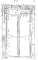
- Figure 1 is a front view, interrupted and in part sectiort, of a French window, the counterframe of which is integral with the framework of the plant; in the same Figure 1 the lower part of the counterframe and frame of a window with a sill is indicated with dashed lines;
- Figure 2 is a left side view,, interrupted and in part sec tion, of the heating and conditioning plant with aspirator and heat exchanger;
- Figure 3 is a side view, from the opposite side than that of Figure 2, of the same plant;
- Figure 4 is the section IV-IV of Figure 2;
- Figure 5 is the section V-V of Figure 2.
- The indications are as follows: 1 and 2 are the frames of the French window; 3 is the counterframe of the
frames frames headers 8, the shaft of which is supported by thebase plate 9 of the case by means of theelements 10; 11 12 and 13 indicate respectively a pulley keyed on the drum shaft withheaders 8, the manoeuvring belt of therolling shutter 7 and the container for the winding of the belt itself; 14 indicates the side panels of the case having abase plate 9; 15 is the upper panel of the case of thedrum 8 or another closing device; 16 indicates the removable cover of the case, 17 a guard for the fixing of the sliding rod of the curtain supports behind the case; 18 indicates the upper and lower insulating panels to protect the room from loss of heat to the outside: 19 indi cates an upper insulating panel on thewall 15 to avoid loss of heat from the fluid distributor to the room; 20 and 21 indicate vertical through tubes that are part of the feeding and discharge circuit of the centralized heading or cooling fluid passing through the tubularvertical heat exchanger 22, communicating in the inferior part with thefan 24 by means of atubular fitting 23, saidfan 24 sucking the air from the lower part of the room, through thefilter 25 of the opening of themanifold 26 according to thearrows 27; 28 indicates a cock to interrupt the flow of the fluid through theheat exchanger 22; 29 indi cates a side cell communicating with theheat exchanger 22 for the housing of thehumidifier 30; 31 indicates the front face of a vertical cover having aside wall 32 to shield, also in an aesthetical way, the rising column of the plant forming air rising; 33 indicates one side of the said cover inclined towards the inside having an aesthetical as well as a containing function, where thesuction manifold 26 opens; 34 indicates an inside terminal leading edge of the said cover, 35 an elbow fitting to conduct the treated air from the heat exchanger to the air distributor; 36 and 37 indicate the upper and lower sides of the crosspiece of the two risers forming the hous ing of the distributor of air to the room equipped with curvedvertical conveying diaphragms 38 closed between theside walls insulating panel 19 supported by theupper plate 15 containing the winding drum of therolling shutter 7; 41 indicates the air deflector elements conveying the air downwards and possibly movable; 42 indicates a verti cal tubular through element contained at the inside of thevertical cover 43 specularly symmetrical with thevertical cover element 42 being intended to convey other tubes for purposes that have nothing to do with the plant, such as for instance the water discharge, the water supply plant, the electric system, the telephone and television system axsxox; 44 in dicates the line of the floor; 45; 46, 47 indicate respec tively the two outer sides of the portal risers for the fixing of the plant to the masonry and the upper side of the portal to be fixed to the ceiling; 48 and 49 indicate two box elements intended to close the lower part of the spaces of thecovers box elements wall 42 of the portal; 56 indicates an insulating panel inserted between the tubular element of theheat exchanger 22 and theback wall 57 forming the upper connexion of the back walls of the two portal risers; 58 indicates the guide_ of the curtain supports which are not represented; 59 in dicates the guide pair of therolling shutter beam 53; 61 indicates the arrows showing the direction of the air yielded to the room, 62 a box structure surrounding peripherally thedeflectors 41 and fixed to thewall 45, riser of the portal of the frame;63 indicates inner tubu lar elements, for instance of a heat exchanger; 64 and 65 indicate the vertical inner supporting walls of the two risers, which have a straight line section substantial ly of U shape, equipped withvertical back walls niches 68 placed into the masonry at the sides of the window opening 69 with a limited depth at thefront face 70 of thecounterframe 3 or even superior to the face itself; in the upper part of the back wall of the two risers extends over the whole length of the opening and the niches of the window or French window and assumes the number 57 (figure 2 and 5); in the lower part these risers end with thebox elements tubular elements 63 of the heat exchanger, The plant operates in the following way: after start thefan 24, the suction opening 25 sucks the air to be treated from the downward part, conveying it through thefitting 23 into thevertical heat exchanger 22, possibly equipped with acell 29 for thehumidifier 30, from which it passes through thefitting 35 into the air distribution case, thediaphragms 38 of which guide the treated air into a normal direction to the plane of the wall; thedeflectors 41 direct the air along course inclined downwards at an an gle depending on the depth and purpose of service of the room, thus determining a uniform air circulation with consequent uniform temperature distribution; it is intended for heating purposes, that a natural air circulation can be obtained, when the heat exchanger is running, depending on the length of the rising tubular column forming the ver tical part of the course of the air; thus thefan 24 has to intervene only in case of necessity by means of a manual control or a thermostat or by means of a proper adjusting device of the temperature with a programme according to the hours of the day and the rooms themselves, permitting to maintain a temperature of 15 - 16°C in the absence of persons by means of radiation or natural convection, which can rather quickly be increased by intervention of thefan 24, which consequently means a considerable saving of energy, In the practical realization, the metal materials forming the elements of the portal and the plant, with the exception of the insulating materials, can be chosen according to the special, also aesthetical, requirements; the same is true also for the straight line sections of the portal risers, which, moreover, must meet also the requirements of good ra diation and good natural convection of the heat in the envi ronment. - Moreover, the plant might present modifications, such as, for instance, the following: the
tube 42 of the right-hand riser might be eliminated to give way to a treating device like the one in the left-hand riser; moreover, thetube 42 might remain at its place even in case of a repetition of the treatment device in the right-hand riser,-it might even be added in the left-hand riser, as it is foreseen that thediaphragms 38 are distributed in two specularly simme- trical formations in the case of double suction; further, theheat exchanger 22 might be of any suitable type and the opening 25 might be in the front instead of being located at an inwardly inclined side, or, in case of a window with sill, it might even be located in a cross element, For aesthetical reasons, it is also foreseen, that it is sufficient in a room with two or more windows or French windows to use only one of them for the treatment of the air in the room, whilst the other one or the other ones are installed of the same type but without inside plant. Moreover, it is foreseen, that the method and the plant can be applied also to doors and windows without rolling shutters, which means an evident simplification and the elimination of the winding drum of therolling shutter 7, of its container case, of theguide pair 59 and of thebelt 12; this permits moreover to decrease the encumberment and to increase the span of the windows and French windows. Finally, the portal should obviously be equipped with more than two active or inactive risers in the case of two or more windows or French windows.
Claims (8)
1, Method for the heating and/or conditioning of rooms, intended for air treatment by means of a heat exchanger fed with heating or cooling fluid coming from a central generating system and of possible humidifier, natural and/ or forced treated air circulation in the room and paoia- tion of heat in the room, characterized by the fact that the air to be treated taken from one or both lower parts of the sides of a window or French window is conveyed, respectively, into one or two vertical radiating ducts situated at the sides of the said win dow or French window and being part with these of a heating and/or conditioning plant, in order to be treated and let into the room above the said window or French window. 2x Plant for heating and/or conditioning of rooms working according to the method of claim 1, including at least one vertical duct with at least one fan inserted into it in order to obtain the suction of the air through the fil ter, with which the lower opening of the duct is equipped, and its passage through at least one heat exchanger fed by tubes conveying a centralized fluid and a possible humidi fier situated in said duct, and a distributing element in the upper part for distribution of the treated air from a bove, the superior distributing element receiving the air from the duct by means of diaphragms which deviate it at 90° and of following air deflectors, which can be moved downwards, characterized by the fact that it mainly includes in a prefabricated structure a hollow portal of upturned U shape, which sur rounds the frame of the window or the French window on three sides and supports it and which is recessed in a ni che prearranged in the masonry, from which it protrudes into the room to be heated and/or conditioned, one or both of the hollow risers of the said portals forming a verti- cal duct for the suction and treatment of the air and for the passage of tubes and ducts of the plant itself and/or other systems and facilities; the hollow crosspiece which connects in the upper part the hollow risers forming a ca se for the distribution add the direction of the treated air flow in the room.
3. Plant according to claim 2 characterized by the fact that a case containing the winding drum of the rolling shutter, which is supported by the ground of the case it self in a rotating way, is supported by the risers between the upper side of the frame of the window or French window inserted in the portal of upturned U shape and the lower side of the hollow crossbeam connecting the hollow risers. 4 Plant according to claim 2 characterized by the fact, that a panel of insulating material (respectively 56 and 60) is applied to the inner side of the walls of each ri ser of the portal and of the air distributing case, which are outwardly in contact with the masonry of the correspond ing prefabricated product.
5. Plant according to claim 2 characterized by the fact that an insulating panel (19) is inserted between the wall (15) and the above wall (3.6) of the air distributor.
6. Plant according to claim 3 characterized by the fact that the inner face of the case cover containing the drum (8) and of the back wall of the case itself are covered by insulating material (18).
7. Plant according to claims 2 and 3 characterized by the fact that each hollow riser of the portal consists of two parts, one bearing part (64, 65) with straight line section of U shape, which supports also the upper air distribution case and the drum container case (8) completed by the back wall (66, 67) and the side wall (45, 46), respectively for fixing said portal to the counterframe (3) of the window frame or French window frame (1, 2) and to the masonry of the niche (68) containing the portal; the other one forming the cover of each hollow riser serves as front closu re of the vertical duct to obtain convection and radiation and projects into the room to be heated and/or conditioned.
8. Plant according to claim 2, characterized by the fact, that an independent vertical duct, which communicates in the upper part with the said hollow crosspiece is contained in the inside of the riser of the portal and encloses, in the indicated order: the opening (26) with filter (25) lo cated in the lower part of the housing, the fan (24), the heat exchanger (22) and the cell of the humidifier (29).
9. Plant according to claim 2 characterized by the fact that, in the case of a window with sill, the air suction opening, simple or multiple, is located in a cross duct con necting the two risers of the portal at their lower part.
10. Plant according to claim 2 characterized by the fact that the base of each hollow riser, having the shape of a hollow socle (48, 49) and equipped with the same straight line section form of the corresponding hollow riser, into which it is fixed, is on the other hand fixed to the floor; it is foreseen that a tube (50) connects each pair of said socles (48, 49) to allow the inside passage of one or more other plants or facilities.
Applications Claiming Priority (2)
| Application Number | Priority Date | Filing Date | Title |
|---|---|---|---|
| IT40027/78A IT1103981B (en) | 1978-02-24 | 1978-02-24 | METHOD AND SYSTEM FOR HEATING AND OR CONDITIONING OF ENVIRONMENTS |
| IT4002778 | 1978-02-24 |
Publications (2)
| Publication Number | Publication Date |
|---|---|
| EP0003811A2 true EP0003811A2 (en) | 1979-09-05 |
| EP0003811A3 EP0003811A3 (en) | 1979-10-31 |
Family
ID=11246774
Family Applications (1)
| Application Number | Title | Priority Date | Filing Date |
|---|---|---|---|
| EP79100462A Withdrawn EP0003811A3 (en) | 1978-02-24 | 1979-02-16 | Method and plant for the heating and/or conditioning of rooms |
Country Status (2)
| Country | Link |
|---|---|
| EP (1) | EP0003811A3 (en) |
| IT (1) | IT1103981B (en) |
Cited By (7)
| Publication number | Priority date | Publication date | Assignee | Title |
|---|---|---|---|---|
| GB2130360A (en) * | 1982-10-20 | 1984-05-31 | Yoshida Kogyo Kk | Ventilation system of a building |
| EP0389021A2 (en) * | 1989-03-20 | 1990-09-26 | Jozef De Lepeleire | Hot air induction and diffusion unit for heating a space, for example a room |
| EP1645809A1 (en) * | 2003-05-27 | 2006-04-12 | Xiaosong Xiao | Integral air conditioner |
| AT511296A1 (en) * | 2011-03-08 | 2012-10-15 | Rettig Austria Gmbh | HEAT HEAT SINK |
| IT201700024881A1 (en) * | 2017-03-07 | 2018-09-07 | Alpac S R L Unipersonale | MULTIFUNCTIONAL THERMO INSULATING MONOBLOCK FOR HOLES FOR WINDOWS AND DEHUMIDIFICATION UNIT INCLUDED IN SUCH MONOBLOC |
| IT201700024876A1 (en) * | 2017-03-07 | 2018-09-07 | Alpac S R L Unipersonale | MULTIFUNCTIONAL THERMO-INSULATING MONOBLOCK STRUCTURE FOR HOLES FOR WINDOWS AND AIR TREATMENT UNIT INCLUDED IN SUCH A MONOBLOCK |
| CN112594765A (en) * | 2021-01-13 | 2021-04-02 | 文配良 | Warmer capable of humidifying |
Families Citing this family (4)
| Publication number | Priority date | Publication date | Assignee | Title |
|---|---|---|---|---|
| US7847260B2 (en) | 2005-02-04 | 2010-12-07 | Dan Inbar | Nuclear threat detection |
| US7820977B2 (en) | 2005-02-04 | 2010-10-26 | Steve Beer | Methods and apparatus for improved gamma spectra generation |
| US8173970B2 (en) | 2005-02-04 | 2012-05-08 | Dan Inbar | Detection of nuclear materials |
| CN106320946A (en) * | 2015-07-01 | 2017-01-11 | 中山市家里家外家居智能系统技术有限公司 | Multifunctional intelligent window |
Citations (6)
| Publication number | Priority date | Publication date | Assignee | Title |
|---|---|---|---|---|
| US1553507A (en) * | 1923-08-01 | 1925-09-15 | Campbell Metal Window Corp | Heating and ventilating means for buildings |
| US1977248A (en) * | 1931-04-14 | 1934-10-16 | Doherty Res Co | Air conditioning system |
| US3002078A (en) * | 1958-08-01 | 1961-09-26 | James C Procter | Room ventilating unit |
| BE717626A (en) * | 1967-07-04 | 1969-01-06 | ||
| FR2085473A1 (en) * | 1970-04-24 | 1971-12-24 | Vey Jean | Heating and air conditioning installation set |
| FR2224633A1 (en) * | 1973-04-06 | 1974-10-31 | Calmettes Claude | Air heating unit for windows or doors - has heating elements behind louvres along vert. edge of frame |
Family Cites Families (1)
| Publication number | Priority date | Publication date | Assignee | Title |
|---|---|---|---|---|
| DE1604178B1 (en) * | 1966-02-21 | 1971-02-18 | Ernst Gross | Device for temperature control of a building room |
-
1978
- 1978-02-24 IT IT40027/78A patent/IT1103981B/en active
-
1979
- 1979-02-16 EP EP79100462A patent/EP0003811A3/en not_active Withdrawn
Patent Citations (6)
| Publication number | Priority date | Publication date | Assignee | Title |
|---|---|---|---|---|
| US1553507A (en) * | 1923-08-01 | 1925-09-15 | Campbell Metal Window Corp | Heating and ventilating means for buildings |
| US1977248A (en) * | 1931-04-14 | 1934-10-16 | Doherty Res Co | Air conditioning system |
| US3002078A (en) * | 1958-08-01 | 1961-09-26 | James C Procter | Room ventilating unit |
| BE717626A (en) * | 1967-07-04 | 1969-01-06 | ||
| FR2085473A1 (en) * | 1970-04-24 | 1971-12-24 | Vey Jean | Heating and air conditioning installation set |
| FR2224633A1 (en) * | 1973-04-06 | 1974-10-31 | Calmettes Claude | Air heating unit for windows or doors - has heating elements behind louvres along vert. edge of frame |
Cited By (11)
| Publication number | Priority date | Publication date | Assignee | Title |
|---|---|---|---|---|
| GB2130360A (en) * | 1982-10-20 | 1984-05-31 | Yoshida Kogyo Kk | Ventilation system of a building |
| EP0389021A2 (en) * | 1989-03-20 | 1990-09-26 | Jozef De Lepeleire | Hot air induction and diffusion unit for heating a space, for example a room |
| EP0389021A3 (en) * | 1989-03-20 | 1991-06-05 | Jozef De Lepeleire | Hot air induction and diffusion unit for heating a space, for example a room |
| EP1645809A1 (en) * | 2003-05-27 | 2006-04-12 | Xiaosong Xiao | Integral air conditioner |
| EP1645809A4 (en) * | 2003-05-27 | 2009-01-14 | Xiaosong Xiao | Integral air conditioner |
| AT511296A1 (en) * | 2011-03-08 | 2012-10-15 | Rettig Austria Gmbh | HEAT HEAT SINK |
| AT511296B1 (en) * | 2011-03-08 | 2013-01-15 | Rettig Austria Gmbh | HEAT HEAT SINK |
| IT201700024881A1 (en) * | 2017-03-07 | 2018-09-07 | Alpac S R L Unipersonale | MULTIFUNCTIONAL THERMO INSULATING MONOBLOCK FOR HOLES FOR WINDOWS AND DEHUMIDIFICATION UNIT INCLUDED IN SUCH MONOBLOC |
| IT201700024876A1 (en) * | 2017-03-07 | 2018-09-07 | Alpac S R L Unipersonale | MULTIFUNCTIONAL THERMO-INSULATING MONOBLOCK STRUCTURE FOR HOLES FOR WINDOWS AND AIR TREATMENT UNIT INCLUDED IN SUCH A MONOBLOCK |
| EP3372908A1 (en) * | 2017-03-07 | 2018-09-12 | Alpac S.R.L. Unipersonale | Multifunctional thermally insulating unit for openings for doors or windows and air treatment apparatus comprised in the unit |
| CN112594765A (en) * | 2021-01-13 | 2021-04-02 | 文配良 | Warmer capable of humidifying |
Also Published As
| Publication number | Publication date |
|---|---|
| IT7840027A0 (en) | 1978-02-24 |
| IT1103981B (en) | 1985-10-14 |
| EP0003811A3 (en) | 1979-10-31 |
Similar Documents
| Publication | Publication Date | Title |
|---|---|---|
| US2210960A (en) | Air conditioning system | |
| EP0003811A2 (en) | Method and plant for the heating and/or conditioning of rooms | |
| EP0199762B1 (en) | Apparatus and method for ventilating rooms | |
| SI20343A (en) | Air conditioning system for buildings and air-conditioned building, especially a zero energy house | |
| US4955285A (en) | System for covering the energy requirement of a room | |
| US20210262679A1 (en) | Convection-enhanced central air conditioning system | |
| EP0366615B1 (en) | Radiant or radiant/ventilating air-conditioning pre-fabricated elements and air-conditioning installation including said elements | |
| US9273463B1 (en) | Curtain wall building environmental control systems and methods | |
| US3833057A (en) | Induced air cooling and heating system | |
| US3439601A (en) | Terminal exit for forced air circulating systems | |
| WO2019050484A1 (en) | Ventilation device | |
| JPH0271027A (en) | Device and method for air conditioning | |
| JPH083368B2 (en) | Air conditioning equipment | |
| KR100314791B1 (en) | HVAC or heating and air conditioning | |
| US20180328610A1 (en) | Air curtain apparatus | |
| US20070293139A1 (en) | System and Method for Inhibiting Moisture and Mold in Structures | |
| JPH05141708A (en) | Radiational panel for cooling and heating | |
| JPS5927149A (en) | Air blow-off device for cooling and heating in interior and exterior structural body | |
| FI83698C (en) | ANORDNING FOER KLIMATISERING AV RUM. | |
| DE4435064A1 (en) | Air guide for ventilating buildings with heat recovery equipment | |
| FI57641C (en) | VAEGGELEMENT FOER BYGGNAD FOERSETT MED ETT VAERME- OCH VENTILATIONSROERSYSTEM | |
| KR102561367B1 (en) | Window System For Ventilation | |
| JPH0214616B2 (en) | ||
| JP2520133B2 (en) | Indoor ventilation | |
| JPH0533856Y2 (en) |
Legal Events
| Date | Code | Title | Description |
|---|---|---|---|
| PUAI | Public reference made under article 153(3) epc to a published international application that has entered the european phase |
Free format text: ORIGINAL CODE: 0009012 |
|
| PUAL | Search report despatched |
Free format text: ORIGINAL CODE: 0009013 |
|
| AK | Designated contracting states |
Designated state(s): BE CH DE FR GB IT LU NL SE |
|
| AK | Designated contracting states |
Designated state(s): BE CH DE FR GB IT LU NL SE |
|
| 17P | Request for examination filed | ||
| STAA | Information on the status of an ep patent application or granted ep patent |
Free format text: STATUS: THE APPLICATION IS DEEMED TO BE WITHDRAWN |
|
| 18D | Application deemed to be withdrawn |
Effective date: 19810525 |
|
| RIN1 | Information on inventor provided before grant (corrected) |
Inventor name: SOLA, CLAUDIO Inventor name: ROLI, ANTONIO |