EP0003176A1 - A machine for packaging items into plastics bags, and a sealing device for use therewith - Google Patents
A machine for packaging items into plastics bags, and a sealing device for use therewith Download PDFInfo
- Publication number
- EP0003176A1 EP0003176A1 EP19790300044 EP79300044A EP0003176A1 EP 0003176 A1 EP0003176 A1 EP 0003176A1 EP 19790300044 EP19790300044 EP 19790300044 EP 79300044 A EP79300044 A EP 79300044A EP 0003176 A1 EP0003176 A1 EP 0003176A1
- Authority
- EP
- European Patent Office
- Prior art keywords
- sealing device
- jaw
- wire
- heating element
- machine
- Prior art date
- Legal status (The legal status is an assumption and is not a legal conclusion. Google has not performed a legal analysis and makes no representation as to the accuracy of the status listed.)
- Granted
Links
- 238000007789 sealing Methods 0.000 title claims abstract description 42
- 239000004033 plastic Substances 0.000 title claims abstract description 29
- 229920003023 plastic Polymers 0.000 title claims abstract description 29
- 238000004806 packaging method and process Methods 0.000 title claims abstract description 6
- 239000000463 material Substances 0.000 claims abstract description 23
- 238000010438 heat treatment Methods 0.000 claims description 17
- 230000005611 electricity Effects 0.000 claims description 4
- 230000001681 protective effect Effects 0.000 claims description 4
- 239000002699 waste material Substances 0.000 claims description 4
- 239000003365 glass fiber Substances 0.000 claims description 3
- -1 polytetrafluoroethylene Polymers 0.000 claims description 3
- 229920002379 silicone rubber Polymers 0.000 claims description 3
- 239000004945 silicone rubber Substances 0.000 claims description 3
- 238000001816 cooling Methods 0.000 claims description 2
- 239000011248 coating agent Substances 0.000 claims 2
- 238000000576 coating method Methods 0.000 claims 2
- 229920001343 polytetrafluoroethylene Polymers 0.000 claims 2
- 239000004810 polytetrafluoroethylene Substances 0.000 claims 2
- 239000011253 protective coating Substances 0.000 claims 1
- 239000004744 fabric Substances 0.000 description 5
- 239000004411 aluminium Substances 0.000 description 4
- 229910052782 aluminium Inorganic materials 0.000 description 4
- XAGFODPZIPBFFR-UHFFFAOYSA-N aluminium Chemical compound [Al] XAGFODPZIPBFFR-UHFFFAOYSA-N 0.000 description 4
- 239000004809 Teflon Substances 0.000 description 3
- 229920006362 Teflon® Polymers 0.000 description 3
- BFKJFAAPBSQJPD-UHFFFAOYSA-N tetrafluoroethene Chemical compound FC(F)=C(F)F BFKJFAAPBSQJPD-UHFFFAOYSA-N 0.000 description 3
- 239000002390 adhesive tape Substances 0.000 description 2
- 229910052751 metal Inorganic materials 0.000 description 2
- 239000002184 metal Substances 0.000 description 2
- 230000003647 oxidation Effects 0.000 description 2
- 238000007254 oxidation reaction Methods 0.000 description 2
- 239000000779 smoke Substances 0.000 description 2
- 229920005439 Perspex® Polymers 0.000 description 1
- 239000004743 Polypropylene Substances 0.000 description 1
- 238000003915 air pollution Methods 0.000 description 1
- 229910045601 alloy Inorganic materials 0.000 description 1
- 239000000956 alloy Substances 0.000 description 1
- 230000015572 biosynthetic process Effects 0.000 description 1
- 230000006835 compression Effects 0.000 description 1
- 238000007906 compression Methods 0.000 description 1
- 239000000835 fiber Substances 0.000 description 1
- 229910001120 nichrome Inorganic materials 0.000 description 1
- 239000004926 polymethyl methacrylate Substances 0.000 description 1
- 229920001155 polypropylene Polymers 0.000 description 1
Images
Classifications
-
- B—PERFORMING OPERATIONS; TRANSPORTING
- B29—WORKING OF PLASTICS; WORKING OF SUBSTANCES IN A PLASTIC STATE IN GENERAL
- B29C—SHAPING OR JOINING OF PLASTICS; SHAPING OF MATERIAL IN A PLASTIC STATE, NOT OTHERWISE PROVIDED FOR; AFTER-TREATMENT OF THE SHAPED PRODUCTS, e.g. REPAIRING
- B29C65/00—Joining or sealing of preformed parts, e.g. welding of plastics materials; Apparatus therefor
- B29C65/02—Joining or sealing of preformed parts, e.g. welding of plastics materials; Apparatus therefor by heating, with or without pressure
- B29C65/18—Joining or sealing of preformed parts, e.g. welding of plastics materials; Apparatus therefor by heating, with or without pressure using heated tools
-
- B—PERFORMING OPERATIONS; TRANSPORTING
- B29—WORKING OF PLASTICS; WORKING OF SUBSTANCES IN A PLASTIC STATE IN GENERAL
- B29C—SHAPING OR JOINING OF PLASTICS; SHAPING OF MATERIAL IN A PLASTIC STATE, NOT OTHERWISE PROVIDED FOR; AFTER-TREATMENT OF THE SHAPED PRODUCTS, e.g. REPAIRING
- B29C65/00—Joining or sealing of preformed parts, e.g. welding of plastics materials; Apparatus therefor
- B29C65/02—Joining or sealing of preformed parts, e.g. welding of plastics materials; Apparatus therefor by heating, with or without pressure
- B29C65/18—Joining or sealing of preformed parts, e.g. welding of plastics materials; Apparatus therefor by heating, with or without pressure using heated tools
- B29C65/22—Heated wire resistive ribbon, resistive band or resistive strip
- B29C65/221—Heated wire resistive ribbon, resistive band or resistive strip characterised by the type of heated wire, resistive ribbon, band or strip
- B29C65/222—Heated wire resistive ribbon, resistive band or resistive strip characterised by the type of heated wire, resistive ribbon, band or strip comprising at least a single heated wire
-
- B—PERFORMING OPERATIONS; TRANSPORTING
- B29—WORKING OF PLASTICS; WORKING OF SUBSTANCES IN A PLASTIC STATE IN GENERAL
- B29C—SHAPING OR JOINING OF PLASTICS; SHAPING OF MATERIAL IN A PLASTIC STATE, NOT OTHERWISE PROVIDED FOR; AFTER-TREATMENT OF THE SHAPED PRODUCTS, e.g. REPAIRING
- B29C65/00—Joining or sealing of preformed parts, e.g. welding of plastics materials; Apparatus therefor
- B29C65/02—Joining or sealing of preformed parts, e.g. welding of plastics materials; Apparatus therefor by heating, with or without pressure
- B29C65/18—Joining or sealing of preformed parts, e.g. welding of plastics materials; Apparatus therefor by heating, with or without pressure using heated tools
- B29C65/22—Heated wire resistive ribbon, resistive band or resistive strip
- B29C65/221—Heated wire resistive ribbon, resistive band or resistive strip characterised by the type of heated wire, resistive ribbon, band or strip
- B29C65/224—Heated wire resistive ribbon, resistive band or resistive strip characterised by the type of heated wire, resistive ribbon, band or strip being a resistive ribbon, a resistive band or a resistive strip
-
- B—PERFORMING OPERATIONS; TRANSPORTING
- B29—WORKING OF PLASTICS; WORKING OF SUBSTANCES IN A PLASTIC STATE IN GENERAL
- B29C—SHAPING OR JOINING OF PLASTICS; SHAPING OF MATERIAL IN A PLASTIC STATE, NOT OTHERWISE PROVIDED FOR; AFTER-TREATMENT OF THE SHAPED PRODUCTS, e.g. REPAIRING
- B29C65/00—Joining or sealing of preformed parts, e.g. welding of plastics materials; Apparatus therefor
- B29C65/02—Joining or sealing of preformed parts, e.g. welding of plastics materials; Apparatus therefor by heating, with or without pressure
- B29C65/18—Joining or sealing of preformed parts, e.g. welding of plastics materials; Apparatus therefor by heating, with or without pressure using heated tools
- B29C65/22—Heated wire resistive ribbon, resistive band or resistive strip
- B29C65/228—Heated wire resistive ribbon, resistive band or resistive strip characterised by the means for electrically connecting the ends of said heated wire, resistive ribbon, resistive band or resistive strip
-
- B—PERFORMING OPERATIONS; TRANSPORTING
- B29—WORKING OF PLASTICS; WORKING OF SUBSTANCES IN A PLASTIC STATE IN GENERAL
- B29C—SHAPING OR JOINING OF PLASTICS; SHAPING OF MATERIAL IN A PLASTIC STATE, NOT OTHERWISE PROVIDED FOR; AFTER-TREATMENT OF THE SHAPED PRODUCTS, e.g. REPAIRING
- B29C65/00—Joining or sealing of preformed parts, e.g. welding of plastics materials; Apparatus therefor
- B29C65/02—Joining or sealing of preformed parts, e.g. welding of plastics materials; Apparatus therefor by heating, with or without pressure
- B29C65/18—Joining or sealing of preformed parts, e.g. welding of plastics materials; Apparatus therefor by heating, with or without pressure using heated tools
- B29C65/22—Heated wire resistive ribbon, resistive band or resistive strip
- B29C65/229—Heated wire resistive ribbon, resistive band or resistive strip characterised by the means for tensioning said heated wire, resistive ribbon, resistive band or resistive strip
-
- B—PERFORMING OPERATIONS; TRANSPORTING
- B29—WORKING OF PLASTICS; WORKING OF SUBSTANCES IN A PLASTIC STATE IN GENERAL
- B29C—SHAPING OR JOINING OF PLASTICS; SHAPING OF MATERIAL IN A PLASTIC STATE, NOT OTHERWISE PROVIDED FOR; AFTER-TREATMENT OF THE SHAPED PRODUCTS, e.g. REPAIRING
- B29C65/00—Joining or sealing of preformed parts, e.g. welding of plastics materials; Apparatus therefor
- B29C65/74—Joining or sealing of preformed parts, e.g. welding of plastics materials; Apparatus therefor by welding and severing, or by joining and severing, the severing being performed in the area to be joined, next to the area to be joined, in the joint area or next to the joint area
- B29C65/745—Joining or sealing of preformed parts, e.g. welding of plastics materials; Apparatus therefor by welding and severing, or by joining and severing, the severing being performed in the area to be joined, next to the area to be joined, in the joint area or next to the joint area using a single unit having both a severing tool and a welding tool
- B29C65/7453—Joining or sealing of preformed parts, e.g. welding of plastics materials; Apparatus therefor by welding and severing, or by joining and severing, the severing being performed in the area to be joined, next to the area to be joined, in the joint area or next to the joint area using a single unit having both a severing tool and a welding tool the severing tool being a wire
-
- B—PERFORMING OPERATIONS; TRANSPORTING
- B29—WORKING OF PLASTICS; WORKING OF SUBSTANCES IN A PLASTIC STATE IN GENERAL
- B29C—SHAPING OR JOINING OF PLASTICS; SHAPING OF MATERIAL IN A PLASTIC STATE, NOT OTHERWISE PROVIDED FOR; AFTER-TREATMENT OF THE SHAPED PRODUCTS, e.g. REPAIRING
- B29C66/00—General aspects of processes or apparatus for joining preformed parts
- B29C66/004—Preventing sticking together, e.g. of some areas of the parts to be joined
- B29C66/0042—Preventing sticking together, e.g. of some areas of the parts to be joined of the joining tool and the parts to be joined
- B29C66/0044—Preventing sticking together, e.g. of some areas of the parts to be joined of the joining tool and the parts to be joined using a separating sheet, e.g. fixed on the joining tool
- B29C66/00441—Preventing sticking together, e.g. of some areas of the parts to be joined of the joining tool and the parts to be joined using a separating sheet, e.g. fixed on the joining tool movable, e.g. mounted on reels
-
- B—PERFORMING OPERATIONS; TRANSPORTING
- B29—WORKING OF PLASTICS; WORKING OF SUBSTANCES IN A PLASTIC STATE IN GENERAL
- B29C—SHAPING OR JOINING OF PLASTICS; SHAPING OF MATERIAL IN A PLASTIC STATE, NOT OTHERWISE PROVIDED FOR; AFTER-TREATMENT OF THE SHAPED PRODUCTS, e.g. REPAIRING
- B29C66/00—General aspects of processes or apparatus for joining preformed parts
- B29C66/01—General aspects dealing with the joint area or with the area to be joined
- B29C66/05—Particular design of joint configurations
- B29C66/10—Particular design of joint configurations particular design of the joint cross-sections
- B29C66/11—Joint cross-sections comprising a single joint-segment, i.e. one of the parts to be joined comprising a single joint-segment in the joint cross-section
- B29C66/112—Single lapped joints
- B29C66/1122—Single lap to lap joints, i.e. overlap joints
-
- B—PERFORMING OPERATIONS; TRANSPORTING
- B29—WORKING OF PLASTICS; WORKING OF SUBSTANCES IN A PLASTIC STATE IN GENERAL
- B29C—SHAPING OR JOINING OF PLASTICS; SHAPING OF MATERIAL IN A PLASTIC STATE, NOT OTHERWISE PROVIDED FOR; AFTER-TREATMENT OF THE SHAPED PRODUCTS, e.g. REPAIRING
- B29C66/00—General aspects of processes or apparatus for joining preformed parts
- B29C66/40—General aspects of joining substantially flat articles, e.g. plates, sheets or web-like materials; Making flat seams in tubular or hollow articles; Joining single elements to substantially flat surfaces
- B29C66/41—Joining substantially flat articles ; Making flat seams in tubular or hollow articles
- B29C66/43—Joining a relatively small portion of the surface of said articles
- B29C66/431—Joining the articles to themselves
- B29C66/4312—Joining the articles to themselves for making flat seams in tubular or hollow articles, e.g. transversal seams
- B29C66/43121—Closing the ends of tubular or hollow single articles, e.g. closing the ends of bags
-
- B—PERFORMING OPERATIONS; TRANSPORTING
- B29—WORKING OF PLASTICS; WORKING OF SUBSTANCES IN A PLASTIC STATE IN GENERAL
- B29C—SHAPING OR JOINING OF PLASTICS; SHAPING OF MATERIAL IN A PLASTIC STATE, NOT OTHERWISE PROVIDED FOR; AFTER-TREATMENT OF THE SHAPED PRODUCTS, e.g. REPAIRING
- B29C66/00—General aspects of processes or apparatus for joining preformed parts
- B29C66/80—General aspects of machine operations or constructions and parts thereof
-
- B—PERFORMING OPERATIONS; TRANSPORTING
- B29—WORKING OF PLASTICS; WORKING OF SUBSTANCES IN A PLASTIC STATE IN GENERAL
- B29C—SHAPING OR JOINING OF PLASTICS; SHAPING OF MATERIAL IN A PLASTIC STATE, NOT OTHERWISE PROVIDED FOR; AFTER-TREATMENT OF THE SHAPED PRODUCTS, e.g. REPAIRING
- B29C66/00—General aspects of processes or apparatus for joining preformed parts
- B29C66/80—General aspects of machine operations or constructions and parts thereof
- B29C66/81—General aspects of the pressing elements, i.e. the elements applying pressure on the parts to be joined in the area to be joined, e.g. the welding jaws or clamps
- B29C66/816—General aspects of the pressing elements, i.e. the elements applying pressure on the parts to be joined in the area to be joined, e.g. the welding jaws or clamps characterised by the mounting of the pressing elements, e.g. of the welding jaws or clamps
- B29C66/8167—Quick change joining tools or surfaces
-
- B—PERFORMING OPERATIONS; TRANSPORTING
- B29—WORKING OF PLASTICS; WORKING OF SUBSTANCES IN A PLASTIC STATE IN GENERAL
- B29C—SHAPING OR JOINING OF PLASTICS; SHAPING OF MATERIAL IN A PLASTIC STATE, NOT OTHERWISE PROVIDED FOR; AFTER-TREATMENT OF THE SHAPED PRODUCTS, e.g. REPAIRING
- B29C66/00—General aspects of processes or apparatus for joining preformed parts
- B29C66/80—General aspects of machine operations or constructions and parts thereof
- B29C66/81—General aspects of the pressing elements, i.e. the elements applying pressure on the parts to be joined in the area to be joined, e.g. the welding jaws or clamps
- B29C66/818—General aspects of the pressing elements, i.e. the elements applying pressure on the parts to be joined in the area to be joined, e.g. the welding jaws or clamps characterised by the cooling constructional aspects, or by the thermal or electrical insulating or conducting constructional aspects of the welding jaws or of the clamps ; comprising means for compensating for the thermal expansion of the welding jaws or of the clamps
-
- B—PERFORMING OPERATIONS; TRANSPORTING
- B29—WORKING OF PLASTICS; WORKING OF SUBSTANCES IN A PLASTIC STATE IN GENERAL
- B29C—SHAPING OR JOINING OF PLASTICS; SHAPING OF MATERIAL IN A PLASTIC STATE, NOT OTHERWISE PROVIDED FOR; AFTER-TREATMENT OF THE SHAPED PRODUCTS, e.g. REPAIRING
- B29C66/00—General aspects of processes or apparatus for joining preformed parts
- B29C66/80—General aspects of machine operations or constructions and parts thereof
- B29C66/81—General aspects of the pressing elements, i.e. the elements applying pressure on the parts to be joined in the area to be joined, e.g. the welding jaws or clamps
- B29C66/818—General aspects of the pressing elements, i.e. the elements applying pressure on the parts to be joined in the area to be joined, e.g. the welding jaws or clamps characterised by the cooling constructional aspects, or by the thermal or electrical insulating or conducting constructional aspects of the welding jaws or of the clamps ; comprising means for compensating for the thermal expansion of the welding jaws or of the clamps
- B29C66/8181—General aspects of the pressing elements, i.e. the elements applying pressure on the parts to be joined in the area to be joined, e.g. the welding jaws or clamps characterised by the cooling constructional aspects, or by the thermal or electrical insulating or conducting constructional aspects of the welding jaws or of the clamps ; comprising means for compensating for the thermal expansion of the welding jaws or of the clamps characterised by the cooling constructional aspects
- B29C66/81811—General aspects of the pressing elements, i.e. the elements applying pressure on the parts to be joined in the area to be joined, e.g. the welding jaws or clamps characterised by the cooling constructional aspects, or by the thermal or electrical insulating or conducting constructional aspects of the welding jaws or of the clamps ; comprising means for compensating for the thermal expansion of the welding jaws or of the clamps characterised by the cooling constructional aspects of the welding jaws
- B29C66/81812—General aspects of the pressing elements, i.e. the elements applying pressure on the parts to be joined in the area to be joined, e.g. the welding jaws or clamps characterised by the cooling constructional aspects, or by the thermal or electrical insulating or conducting constructional aspects of the welding jaws or of the clamps ; comprising means for compensating for the thermal expansion of the welding jaws or of the clamps characterised by the cooling constructional aspects of the welding jaws the welding jaws being cooled from the outside, e.g. by blowing a gas or spraying a liquid
-
- B—PERFORMING OPERATIONS; TRANSPORTING
- B29—WORKING OF PLASTICS; WORKING OF SUBSTANCES IN A PLASTIC STATE IN GENERAL
- B29C—SHAPING OR JOINING OF PLASTICS; SHAPING OF MATERIAL IN A PLASTIC STATE, NOT OTHERWISE PROVIDED FOR; AFTER-TREATMENT OF THE SHAPED PRODUCTS, e.g. REPAIRING
- B29C66/00—General aspects of processes or apparatus for joining preformed parts
- B29C66/80—General aspects of machine operations or constructions and parts thereof
- B29C66/82—Pressure application arrangements, e.g. transmission or actuating mechanisms for joining tools or clamps
- B29C66/822—Transmission mechanisms
- B29C66/8221—Scissor or lever mechanisms, i.e. involving a pivot point
-
- B—PERFORMING OPERATIONS; TRANSPORTING
- B29—WORKING OF PLASTICS; WORKING OF SUBSTANCES IN A PLASTIC STATE IN GENERAL
- B29C—SHAPING OR JOINING OF PLASTICS; SHAPING OF MATERIAL IN A PLASTIC STATE, NOT OTHERWISE PROVIDED FOR; AFTER-TREATMENT OF THE SHAPED PRODUCTS, e.g. REPAIRING
- B29C66/00—General aspects of processes or apparatus for joining preformed parts
- B29C66/80—General aspects of machine operations or constructions and parts thereof
- B29C66/83—General aspects of machine operations or constructions and parts thereof characterised by the movement of the joining or pressing tools
- B29C66/832—Reciprocating joining or pressing tools
- B29C66/8324—Joining or pressing tools pivoting around one axis
-
- B—PERFORMING OPERATIONS; TRANSPORTING
- B29—WORKING OF PLASTICS; WORKING OF SUBSTANCES IN A PLASTIC STATE IN GENERAL
- B29C—SHAPING OR JOINING OF PLASTICS; SHAPING OF MATERIAL IN A PLASTIC STATE, NOT OTHERWISE PROVIDED FOR; AFTER-TREATMENT OF THE SHAPED PRODUCTS, e.g. REPAIRING
- B29C66/00—General aspects of processes or apparatus for joining preformed parts
- B29C66/80—General aspects of machine operations or constructions and parts thereof
- B29C66/84—Specific machine types or machines suitable for specific applications
- B29C66/849—Packaging machines
-
- B—PERFORMING OPERATIONS; TRANSPORTING
- B65—CONVEYING; PACKING; STORING; HANDLING THIN OR FILAMENTARY MATERIAL
- B65B—MACHINES, APPARATUS OR DEVICES FOR, OR METHODS OF, PACKAGING ARTICLES OR MATERIALS; UNPACKING
- B65B51/00—Devices for, or methods of, sealing or securing package folds or closures; Devices for gathering or twisting wrappers, or necks of bags
- B65B51/10—Applying or generating heat or pressure or combinations thereof
- B65B51/14—Applying or generating heat or pressure or combinations thereof by reciprocating or oscillating members
- B65B51/146—Closing bags
-
- B—PERFORMING OPERATIONS; TRANSPORTING
- B29—WORKING OF PLASTICS; WORKING OF SUBSTANCES IN A PLASTIC STATE IN GENERAL
- B29C—SHAPING OR JOINING OF PLASTICS; SHAPING OF MATERIAL IN A PLASTIC STATE, NOT OTHERWISE PROVIDED FOR; AFTER-TREATMENT OF THE SHAPED PRODUCTS, e.g. REPAIRING
- B29C66/00—General aspects of processes or apparatus for joining preformed parts
- B29C66/90—Measuring or controlling the joining process
- B29C66/91—Measuring or controlling the joining process by measuring or controlling the temperature, the heat or the thermal flux
- B29C66/914—Measuring or controlling the joining process by measuring or controlling the temperature, the heat or the thermal flux by controlling or regulating the temperature, the heat or the thermal flux
- B29C66/9161—Measuring or controlling the joining process by measuring or controlling the temperature, the heat or the thermal flux by controlling or regulating the temperature, the heat or the thermal flux by controlling or regulating the heat or the thermal flux, i.e. the heat flux
- B29C66/91641—Measuring or controlling the joining process by measuring or controlling the temperature, the heat or the thermal flux by controlling or regulating the temperature, the heat or the thermal flux by controlling or regulating the heat or the thermal flux, i.e. the heat flux the heat or the thermal flux being non-constant over time
- B29C66/91643—Measuring or controlling the joining process by measuring or controlling the temperature, the heat or the thermal flux by controlling or regulating the temperature, the heat or the thermal flux by controlling or regulating the heat or the thermal flux, i.e. the heat flux the heat or the thermal flux being non-constant over time following a heat-time profile
- B29C66/91645—Measuring or controlling the joining process by measuring or controlling the temperature, the heat or the thermal flux by controlling or regulating the temperature, the heat or the thermal flux by controlling or regulating the heat or the thermal flux, i.e. the heat flux the heat or the thermal flux being non-constant over time following a heat-time profile by steps
-
- B—PERFORMING OPERATIONS; TRANSPORTING
- B29—WORKING OF PLASTICS; WORKING OF SUBSTANCES IN A PLASTIC STATE IN GENERAL
- B29C—SHAPING OR JOINING OF PLASTICS; SHAPING OF MATERIAL IN A PLASTIC STATE, NOT OTHERWISE PROVIDED FOR; AFTER-TREATMENT OF THE SHAPED PRODUCTS, e.g. REPAIRING
- B29C66/00—General aspects of processes or apparatus for joining preformed parts
- B29C66/90—Measuring or controlling the joining process
- B29C66/91—Measuring or controlling the joining process by measuring or controlling the temperature, the heat or the thermal flux
- B29C66/914—Measuring or controlling the joining process by measuring or controlling the temperature, the heat or the thermal flux by controlling or regulating the temperature, the heat or the thermal flux
- B29C66/9161—Measuring or controlling the joining process by measuring or controlling the temperature, the heat or the thermal flux by controlling or regulating the temperature, the heat or the thermal flux by controlling or regulating the heat or the thermal flux, i.e. the heat flux
- B29C66/91651—Measuring or controlling the joining process by measuring or controlling the temperature, the heat or the thermal flux by controlling or regulating the temperature, the heat or the thermal flux by controlling or regulating the heat or the thermal flux, i.e. the heat flux by controlling or regulating the heat generated by Joule heating or induction heating
-
- B—PERFORMING OPERATIONS; TRANSPORTING
- B29—WORKING OF PLASTICS; WORKING OF SUBSTANCES IN A PLASTIC STATE IN GENERAL
- B29L—INDEXING SCHEME ASSOCIATED WITH SUBCLASS B29C, RELATING TO PARTICULAR ARTICLES
- B29L2031/00—Other particular articles
- B29L2031/712—Containers; Packaging elements or accessories, Packages
- B29L2031/7128—Bags, sacks, sachets
Definitions
- the known sealers have the disadvantage that they only provide a narrow seal, which is therefore often weak.
- the heating means may comprise an electrical heating element and to increase output of a maching using the sealing device, control means may be provided arranged alternately to supply a pulse-of electricity to the element, furthered by a blast of air to cool the element.
- control means may be provided arranged alternately to supply a pulse-of electricity to the element, furthered by a blast of air to cool the element.
- the element may be mounted on a support (e.g. a hollow jaw) which has passages therethrough, through which the cooling air is directed.
- the invention includes a machine for packaging items into plastics bags, the machine being fitted with a sealing device according to the invention.
- the lower jaw comprises a channel member 19 of aluminium, a Z cross-section aluminium strip 20 being fastened into the channel to define a chamber 21 and a narrower channel 22.
- a strip of protective material 23 which comprises a woven glass fibre material coated with TEFLON.
- Passing through the fabric 25 and one flange of the member 19 is a series of air holes 28, which communicate with the chamber 21. As shown in Figure 2, there are a plurality of these air holes spaced apart along.the length of the jaw. Furthermore there are three spaced apart holes 29 extending through the adhesive tape 27 and the base of the channel member 19, part of these holes also communicating with the chamber 21.
- the upper jaw 13 comprises an elongate aluminium plate 34 which extends between the arms 14. Secured to the lower face of the plate 34 is a metal channel member 38 having a dovetail cross-section. A resilient pad 39 of silicone rubber is slidably mounted in this channel and the lower face of the pad 39 has a layer 40 of TEFLON coated plsss fibre fabric secured thereto. Between the arms 14 there is stretched a cutting wire 41. As shown in Figure 4, one end of the wire passes through one of the arms 14 and is wound around a locking screw 42. The other end of the wire passes through a hole in the other arm 14 and is connected to a rod 43. On the outer end of the rod 43 there is threaded a compression spring 45. The outer end of the rod 43 carries a screw-thread. A first nut 47 is sirewed on tc the rod to compress the spring 45 and hence put the wire 41 under tension. A second locknut 48 is then tightened up against the first nut 47.
- the heating element cools rapidly and as the layers of plastics material also cool, they form a seal, although the scrap skirt at the mouth of the bag has been severed from the remainder of the bag by the wire 41 passinr throurh the softened material. The jaws then open, the scrap is blown away, and the bag slides out of the machine, so that the machine is ready for another cycle.
- the sealing device shown in the Figures enabl s the formation of a seal which is significantly wider, and hence stronger, than the type of seal which can be formed by a conventional heated wire sealing device.
- the wire 41 which splits the sealed area to provide a neat finish, need not be heated.
- both jaws are readily removable from the machine, replacement or repair of the jaws is greatly facilitated.
- the existence of the channel 22 means that the jaw 12 could be used with a hot wire cutting device to provide an even wider seal, if the jaw 12 is utilised with a jaw which has a smothering pad similar to pad 39, and a heated wire offset from this pad, the smothering pad can co-operate with the heating element 24 to provide a wide seal, while the wire passes into the channel 22 to perform a trmring operation.
- the invention is particularly effective for sealing polypropylene or P.V.C. if the wire 41 is mounted on the lower jaw.
- the wire may be stretched over the upper surface of the jaw between the contacts 33, so that an electric current passes through the wire so that the wire is heated sli f htly as well as the element 24.
- the wire may be coated or uncoated.
- a sealing device has other uses. It may be used to free a sealed bag from a stack of continuous plastics material being used to form the bags. It can also be used for any other application where it is desired to seal and cut plastics material.
Landscapes
- Engineering & Computer Science (AREA)
- Mechanical Engineering (AREA)
- Physics & Mathematics (AREA)
- Thermal Sciences (AREA)
- Package Closures (AREA)
Abstract
Description
- The invention relates to a machine for packaging items into plastics bags and to a device for sealing the bags after they have been packed. The sealing device not only heat seals the bag but also cuts through the bag between the edges of the seal to trim off waste at the mouth of the bag and leave a neat, sealed mouth.
- Known heat sealers of this type employ a heated knife or wire which cuts through the plastics material and welds the plastics material together simultaneously. An example is described in United States Patent Specification No.3653177.
- The known sealers have the disadvantage that they only provide a narrow seal, which is therefore often weak.
- The invention as claimed is intended to make it possible to form a seal which can be as wide as desired, while still retaining the good cutting properties of a wire.
- According to the invention separate heat sealing means are used in addition to the cutting wire. The separate heat sealing means can be made substantially wider than the wire.
- Another disadvantage of known devices such as that of U.S. Patent No.3653177 is that there is considerable oxidation of the plastics material bringing about considerable odour and smoke which is unpleasant and dangerous for the operator and causes air pollution. This disadvantage is reduced by a preferred feature of, the invention in which the sealing device comprises a pair of jaws between which the plastics material can be gripped. The jaws effectively smother the area of plastics material being heated, substantially reducing oxidation.
- The use of a pair of jaws also conveniently means that the heating means can be arranged on one jaw and the cutting wire on the other jaw. It is not essential for the cutting wire to be heated.
- The heating means may comprise an electrical heating element and to increase output of a maching using the sealing device, control means may be provided arranged alternately to supply a pulse-of electricity to the element, furthered by a blast of air to cool the element. To faciltate this the element may be mounted on a support (e.g. a hollow jaw) which has passages therethrough, through which the cooling air is directed.
- The invention includes a machine for packaging items into plastics bags, the machine being fitted with a sealing device according to the invention.
- One way of carrying out the invention is described in deatil below with reference to drawings which illustrate only one specific embodiment, in which:-
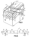
- Figure 1 is a perspective view of a plastics bag handling machine fitted with a'sealing device according to the invention;
- Figure 2 is a front view of a first jaw of the sealing device;'
- Figure 3 is a transverse cross-section through the jaw shown in Figure 2;
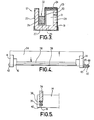
- Figure 4 is a front view of a second jaw of the sealing device; and
- Figure 5 is a transverse cross-section through the jaw shown in Figure 4.
- The machine shown in Figure 1 has an
upper support surface 10 which is inclined at an angle to the horizontal. At the upper end of the support surface there is fitted an embodiment of sealing device according to the invention, indicated generally by the reference numeral 11. The sealing device has a fixedlower jaw 12 and a movableupper jaw 13. Thejaw 13 is fixed between a pair ofarms 14 which arc pivotable aboutpivot points 15 to move thejaw 13 towards and away from the jaw.12. A plastics bag (not shown) can be filled with any desired contents and can then be positioned on thesuport surface 10 with the mouth of the bag projecting over the top of thelower jaw 12. The bar is prevented from slipping downwardly off thesupport surface 10 by a set offingers 17, the position of which is adjustable to suit different sizes of bag.Rollers 16 are provided on thesurface 10. - When a machine cycle is initiated, the
upper jaw 13 moves downwardly to trap the mouth of the bag against thelower jaw 12. A transverse seal is formed across the mouth of the bag and simultaneously a split is formed extending parallel with the seal and lying within the edges of the seal. This split cuts off the waste skirt at the mouth of the bag and leaves a neat finish. Thejaw 13 then rises again, the scrap material is blown out of awaste chute 18 into a collecting container (not shown) at one side of the machine by a jet of air, thefingers 17 then retract, and the bag slides off the machine on therollers 16 either to be received by an operator or by a receptacle or conveyor belt (not shown). The upper part of the machine is covered by aperspex guard 9. The details of the machine other than the sealing device do not form part of this invention and will not therefore be described in detail. - Turning now to the sealing device, the
lower jaw 12 is shown in more detail in Figures 2 and 3. - As best shown in Figure 3, the lower jaw comprises a
channel member 19 of aluminium, a Zcross-section aluminium strip 20 being fastened into the channel to define achamber 21 and a narrower channel 22. On the outer face of the roof of thechamber 21 there is a strip ofprotective material 23 which comprises a woven glass fibre material coated with TEFLON. On top of thisstrip 23 there is a flat metal band of Nichrome Alloy 24, 5/16" wide, which forms an electrical heating element. - The entire upper surface and sides of the
jaw 12 are covered by a layer of TEFLON coatedglass fibre fabric 25. Alocking bar 26, the upper surface of which is coated with the same material, is secured in the bottom of the channel 22 by screwed (not shown). The lower edges of thefabric 25 are joined together by a portion of adhesive tape which covers the lower face of thejaw 12 and overlaps the free edges of thefabric 25. - Passing through the
fabric 25 and one flange of themember 19 is a series ofair holes 28, which communicate with thechamber 21. As shown in Figure 2, there are a plurality of these air holes spaced apart along.the length of the jaw. Furthermore there are three spaced apartholes 29 extending through theadhesive tape 27 and the base of thechannel member 19, part of these holes also communicating with thechamber 21. - As shown in Figure 2, the rear flange of the
channel member 19 is cut away at its ends as shown at 30, to enable the jaw to fit on to the machine, and the front flange and base of thechennel member 19 are completely cut away at the ends of the jaw, so thatinsulating blocks 31 can be screwed to the rear flange. Eachend 32 of the heating element 24 e tends down a sloping portion of the front flange of thechannel member 19 and into one of theinsulating blocks 31, where the end of the element is electrically connected to aterminal 33 projecting downwardly from the associatedinsulating block 31. - The lower jaw can be connected to the machine by plugging the
terminals 33 into sockets on the machine and electrical current can then be supplied to theelement 24 to heat the element. A source of compressed air is also connected to theapertures 29 so that the compressed air can be blown into thechamber 21, exhausting through theapertures 28. - Turning now to Figures 4 and 5, the
upper jaw 13 comprises anelongate aluminium plate 34 which extends between thearms 14. Secured to the lower face of theplate 34 is ametal channel member 38 having a dovetail cross-section. Aresilient pad 39 of silicone rubber is slidably mounted in this channel and the lower face of thepad 39 has alayer 40 of TEFLON coated plsss fibre fabric secured thereto. Between thearms 14 there is stretched acutting wire 41. As shown in Figure 4, one end of the wire passes through one of thearms 14 and is wound around alocking screw 42. The other end of the wire passes through a hole in theother arm 14 and is connected to arod 43. On the outer end of therod 43 there is threaded acompression spring 45. The outer end of therod 43 carries a screw-thread. Afirst nut 47 is sirewed on tc the rod to compress thespring 45 and hence put thewire 41 under tension. Asecond locknut 48 is then tightened up against thefirst nut 47. - The upper jaw is provided with a finger guard for safety purposes. This guard is not part of the invention and will not therefore be described in detail.
- When the sealing device is in use, two layers of plastics material at the mouth of a bag are firmly clamped between the
heating element 24 and thesilicone rubber cushion 39, thewire 41 being crushed against the plastics material. A pulse of electricity is supplied to the heating element by the machine which causes the heating element to heat up very rapidly and melt the two layers of plastics material over a strip-like area which has a width substantially equal to the width of theheating element 24. The crushing action of the jaws causes thewire 41 to be forced through the softened plastics material, splitting the softened area. A blast of compressed air is then fed into thechamber 21, the pulse of electricity having ceased. The heating element cools rapidly and as the layers of plastics material also cool, they form a seal, although the scrap skirt at the mouth of the bag has been severed from the remainder of the bag by thewire 41 passinr throurh the softened material. The jaws then open, the scrap is blown away, and the bag slides out of the machine, so that the machine is ready for another cycle. - The sealing device shown in the Figures enabl s the formation of a seal which is significantly wider, and hence stronger, than the type of seal which can be formed by a conventional heated wire sealing device. The
wire 41, which splits the sealed area to provide a neat finish, need not be heated. - Since the
resilient pad 39 effectively smothers the area of plastics material which is being heated, preventing air from reaching the plastics material, there is substantially no oxidisation of the plastics material and this in turn means that there is substantially no smoke or odour. - Since both jaws are readily removable from the machine, replacement or repair of the jaws is greatly facilitated.
- The invention is not restricted to the details of the foregoing embodiment.
- The existence of the channel 22 means that the
jaw 12 could be used with a hot wire cutting device to provide an even wider seal, if thejaw 12 is utilised with a jaw which has a smothering pad similar to pad 39, and a heated wire offset from this pad, the smothering pad can co-operate with theheating element 24 to provide a wide seal, while the wire passes into the channel 22 to perform a trmring operation. - If desired, where the provision of the channel 22 is not required on the lower jaw, the jaw may have a body comprising a hollow aluminium tube of simple configuration, for example of square or rectangular cross-section. The interior of the tube, or of the jaw shown in Figures 2 and 3, may be diviced into separate compartments spaced apart along the length of the jaw, each compartment having at least one
air inlet aperture 29 andexhaust aperture 28. It is preferred that each compartment has asingle inlet aperture 29 comunicating with a central portion of the compartment and at least two exhaust apertures, communicating with one end portion of the compartment. - We have discovered that the invention is particularly effective for sealing polypropylene or P.V.C. if the
wire 41 is mounted on the lower jaw. The wire may be stretched over the upper surface of the jaw between thecontacts 33, so that an electric current passes through the wire so that the wire is heated slifhtly as well as theelement 24. The wire may be coated or uncoated. - A sealing device according to the invention has other uses. It may be used to free a sealed bag from a stack of continuous plastics material being used to form the bags. It can also be used for any other application where it is desired to seal and cut plastics material.
Claims (15)
Applications Claiming Priority (2)
| Application Number | Priority Date | Filing Date | Title |
|---|---|---|---|
| GB1364/78A GB1600626A (en) | 1978-01-13 | 1978-01-13 | Sealing devices |
| GB136478 | 1978-05-24 |
Publications (2)
| Publication Number | Publication Date |
|---|---|
| EP0003176A1 true EP0003176A1 (en) | 1979-07-25 |
| EP0003176B1 EP0003176B1 (en) | 1981-10-28 |
Family
ID=9720741
Family Applications (1)
| Application Number | Title | Priority Date | Filing Date |
|---|---|---|---|
| EP19790300044 Expired EP0003176B1 (en) | 1978-01-13 | 1979-01-11 | A machine for packaging items into plastics bags, and a sealing device for use therewith |
Country Status (3)
| Country | Link |
|---|---|
| EP (1) | EP0003176B1 (en) |
| DE (1) | DE2961088D1 (en) |
| GB (1) | GB1600626A (en) |
Cited By (1)
| Publication number | Priority date | Publication date | Assignee | Title |
|---|---|---|---|---|
| WO2002083505A3 (en) * | 2001-04-17 | 2003-02-27 | Transave Ltd | Apparatus and method for vacuum packing products |
Citations (6)
| Publication number | Priority date | Publication date | Assignee | Title |
|---|---|---|---|---|
| US2796913A (en) * | 1954-10-04 | 1957-06-25 | Langer | Art of heat sealing and severing thermoplastic films |
| US3234072A (en) * | 1962-06-27 | 1966-02-08 | Mercury Heat Sealing Equipment | Forming and sealing packages |
| DE1213217B (en) * | 1961-01-27 | 1966-03-24 | Ver Leichtmetallwerke Gmbh | Method of manufacturing honeycomb material |
| US3262833A (en) * | 1963-12-17 | 1966-07-26 | Zelnick Seymour | Impulse radiant sealer |
| US3309837A (en) * | 1964-10-21 | 1967-03-21 | Union Carbide Corp | Method and apparatus for producing a package |
| FR2264643A1 (en) * | 1973-03-19 | 1975-10-17 | Platmanufaktur Ab |
-
1978
- 1978-01-13 GB GB1364/78A patent/GB1600626A/en not_active Expired
-
1979
- 1979-01-11 DE DE7979300044T patent/DE2961088D1/en not_active Expired
- 1979-01-11 EP EP19790300044 patent/EP0003176B1/en not_active Expired
Patent Citations (6)
| Publication number | Priority date | Publication date | Assignee | Title |
|---|---|---|---|---|
| US2796913A (en) * | 1954-10-04 | 1957-06-25 | Langer | Art of heat sealing and severing thermoplastic films |
| DE1213217B (en) * | 1961-01-27 | 1966-03-24 | Ver Leichtmetallwerke Gmbh | Method of manufacturing honeycomb material |
| US3234072A (en) * | 1962-06-27 | 1966-02-08 | Mercury Heat Sealing Equipment | Forming and sealing packages |
| US3262833A (en) * | 1963-12-17 | 1966-07-26 | Zelnick Seymour | Impulse radiant sealer |
| US3309837A (en) * | 1964-10-21 | 1967-03-21 | Union Carbide Corp | Method and apparatus for producing a package |
| FR2264643A1 (en) * | 1973-03-19 | 1975-10-17 | Platmanufaktur Ab |
Cited By (3)
| Publication number | Priority date | Publication date | Assignee | Title |
|---|---|---|---|---|
| WO2002083505A3 (en) * | 2001-04-17 | 2003-02-27 | Transave Ltd | Apparatus and method for vacuum packing products |
| US7086212B2 (en) | 2001-04-17 | 2006-08-08 | Transave Limited | Apparatus and method for vacuum packing products |
| CN100465071C (en) * | 2001-04-17 | 2009-03-04 | 特兰萨维有限公司 | Apparatus and method for vacuum packaging products |
Also Published As
| Publication number | Publication date |
|---|---|
| EP0003176B1 (en) | 1981-10-28 |
| DE2961088D1 (en) | 1982-01-07 |
| GB1600626A (en) | 1981-10-21 |
Similar Documents
| Publication | Publication Date | Title |
|---|---|---|
| US5131213A (en) | Sealing jaws | |
| US4014154A (en) | Packaging method and apparatus | |
| US3912575A (en) | Heat sealing apparatus using a wire sealing element | |
| US3867226A (en) | Method for sealing plastic bags | |
| US3965653A (en) | Packaging apparatus | |
| US3047991A (en) | Impulse sealing apparatus | |
| US3234072A (en) | Forming and sealing packages | |
| US3815318A (en) | Packaging method and apparatus | |
| US3112586A (en) | Method and apparatus for forming a covering about a garment | |
| TW247305B (en) | Vertical-type filling and packaging machine | |
| CA2477139C (en) | Apparatus for sealing the overlapping edges of a tubular film | |
| EP0079760B1 (en) | Heat control system for packaging machine | |
| US3409494A (en) | Sealing element for shrink film packaging machine | |
| US2535171A (en) | Heat sealing device | |
| US3043071A (en) | Packaging machine | |
| GB1146959A (en) | Improvements in wrapping methods and apparatus | |
| US4734142A (en) | Bag sealing device | |
| US3587410A (en) | Apparatus for stacking bags | |
| EP0003176B1 (en) | A machine for packaging items into plastics bags, and a sealing device for use therewith | |
| US3420035A (en) | Packaging machine | |
| US3687789A (en) | Heat-sealing apparatus | |
| US4131503A (en) | Method and apparatus for sealing and cutting thermoplastic material | |
| SK282588B6 (en) | Device for making the transverse seams on a bag forming machine | |
| US4223511A (en) | PVC Foil cutter | |
| US3111794A (en) | Sealing apparatus |
Legal Events
| Date | Code | Title | Description |
|---|---|---|---|
| PUAI | Public reference made under article 153(3) epc to a published international application that has entered the european phase |
Free format text: ORIGINAL CODE: 0009012 |
|
| AK | Designated contracting states |
Designated state(s): BE CH DE FR IT LU NL SE |
|
| 17P | Request for examination filed | ||
| GRAA | (expected) grant |
Free format text: ORIGINAL CODE: 0009210 |
|
| AK | Designated contracting states |
Designated state(s): BE CH DE FR IT LU NL SE |
|
| PG25 | Lapsed in a contracting state [announced via postgrant information from national office to epo] |
Ref country code: NL Effective date: 19811028 Ref country code: IT Free format text: LAPSE BECAUSE OF FAILURE TO SUBMIT A TRANSLATION OF THE DESCRIPTION OR TO PAY THE FEE WITHIN THE PRESCRIBED TIME-LIMIT;WARNING: LAPSES OF ITALIAN PATENTS WITH EFFECTIVE DATE BEFORE 2007 MAY HAVE OCCURRED AT ANY TIME BEFORE 2007. THE CORRECT EFFECTIVE DATE MAY BE DIFFERENT FROM THE ONE RECORDED. Effective date: 19811028 Ref country code: CH Effective date: 19811028 Ref country code: BE Effective date: 19811028 |
|
| REF | Corresponds to: |
Ref document number: 2961088 Country of ref document: DE Date of ref document: 19820107 |
|
| PG25 | Lapsed in a contracting state [announced via postgrant information from national office to epo] |
Ref country code: LU Free format text: LAPSE BECAUSE OF NON-PAYMENT OF DUE FEES Effective date: 19820131 |
|
| REG | Reference to a national code |
Ref country code: CH Ref legal event code: PL |
|
| PGFP | Annual fee paid to national office [announced via postgrant information from national office to epo] |
Ref country code: DE Payment date: 19820331 Year of fee payment: 4 |
|
| NLV1 | Nl: lapsed or annulled due to failure to fulfill the requirements of art. 29p and 29m of the patents act | ||
| PG25 | Lapsed in a contracting state [announced via postgrant information from national office to epo] |
Ref country code: SE Effective date: 19820505 |
|
| PGFP | Annual fee paid to national office [announced via postgrant information from national office to epo] |
Ref country code: FR Payment date: 19820709 Year of fee payment: 4 |
|
| PG25 | Lapsed in a contracting state [announced via postgrant information from national office to epo] |
Ref country code: FR Free format text: LAPSE BECAUSE OF NON-PAYMENT OF DUE FEES Effective date: 19830930 |
|
| PG25 | Lapsed in a contracting state [announced via postgrant information from national office to epo] |
Ref country code: DE Effective date: 19831001 |
|
| REG | Reference to a national code |
Ref country code: FR Ref legal event code: ST |
|
| PLBE | No opposition filed within time limit |
Free format text: ORIGINAL CODE: 0009261 |
|
| STAA | Information on the status of an ep patent application or granted ep patent |
Free format text: STATUS: NO OPPOSITION FILED WITHIN TIME LIMIT |