EP0003146A2 - A device for treating waste water by gravitational segregation - Google Patents
A device for treating waste water by gravitational segregation Download PDFInfo
- Publication number
- EP0003146A2 EP0003146A2 EP79200008A EP79200008A EP0003146A2 EP 0003146 A2 EP0003146 A2 EP 0003146A2 EP 79200008 A EP79200008 A EP 79200008A EP 79200008 A EP79200008 A EP 79200008A EP 0003146 A2 EP0003146 A2 EP 0003146A2
- Authority
- EP
- European Patent Office
- Prior art keywords
- channels
- separation
- separation channels
- waste water
- water
- Prior art date
- Legal status (The legal status is an assumption and is not a legal conclusion. Google has not performed a legal analysis and makes no representation as to the accuracy of the status listed.)
- Withdrawn
Links
- 239000002351 wastewater Substances 0.000 title claims abstract description 7
- 238000005204 segregation Methods 0.000 title claims abstract description 5
- 238000000926 separation method Methods 0.000 claims abstract description 42
- 239000000126 substance Substances 0.000 claims abstract description 42
- 239000000203 mixture Substances 0.000 claims description 18
- XLYOFNOQVPJJNP-UHFFFAOYSA-N water Substances O XLYOFNOQVPJJNP-UHFFFAOYSA-N 0.000 claims description 11
- 241001136792 Alle Species 0.000 abstract 2
- 238000005189 flocculation Methods 0.000 description 2
- 230000016615 flocculation Effects 0.000 description 2
- 230000007423 decrease Effects 0.000 description 1
- 230000003247 decreasing effect Effects 0.000 description 1
- 230000005484 gravity Effects 0.000 description 1
- 230000001737 promoting effect Effects 0.000 description 1
- 239000008213 purified water Substances 0.000 description 1
- 230000000630 rising effect Effects 0.000 description 1
Images
Classifications
-
- B—PERFORMING OPERATIONS; TRANSPORTING
- B01—PHYSICAL OR CHEMICAL PROCESSES OR APPARATUS IN GENERAL
- B01D—SEPARATION
- B01D17/00—Separation of liquids, not provided for elsewhere, e.g. by thermal diffusion
- B01D17/02—Separation of non-miscible liquids
- B01D17/0208—Separation of non-miscible liquids by sedimentation
-
- B—PERFORMING OPERATIONS; TRANSPORTING
- B01—PHYSICAL OR CHEMICAL PROCESSES OR APPARATUS IN GENERAL
- B01D—SEPARATION
- B01D17/00—Separation of liquids, not provided for elsewhere, e.g. by thermal diffusion
- B01D17/02—Separation of non-miscible liquids
- B01D17/0208—Separation of non-miscible liquids by sedimentation
- B01D17/0211—Separation of non-miscible liquids by sedimentation with baffles
-
- B—PERFORMING OPERATIONS; TRANSPORTING
- B01—PHYSICAL OR CHEMICAL PROCESSES OR APPARATUS IN GENERAL
- B01D—SEPARATION
- B01D21/00—Separation of suspended solid particles from liquids by sedimentation
- B01D21/0039—Settling tanks provided with contact surfaces, e.g. baffles, particles
- B01D21/0051—Plurality of tube like channels
-
- B—PERFORMING OPERATIONS; TRANSPORTING
- B01—PHYSICAL OR CHEMICAL PROCESSES OR APPARATUS IN GENERAL
- B01D—SEPARATION
- B01D21/00—Separation of suspended solid particles from liquids by sedimentation
- B01D21/0039—Settling tanks provided with contact surfaces, e.g. baffles, particles
- B01D21/0069—Making of contact surfaces, structural details, materials therefor
- B01D21/0075—Contact surfaces having surface features
-
- B—PERFORMING OPERATIONS; TRANSPORTING
- B01—PHYSICAL OR CHEMICAL PROCESSES OR APPARATUS IN GENERAL
- B01D—SEPARATION
- B01D21/00—Separation of suspended solid particles from liquids by sedimentation
- B01D21/10—Settling tanks with multiple outlets for the separated liquids
-
- B—PERFORMING OPERATIONS; TRANSPORTING
- B01—PHYSICAL OR CHEMICAL PROCESSES OR APPARATUS IN GENERAL
- B01D—SEPARATION
- B01D21/00—Separation of suspended solid particles from liquids by sedimentation
- B01D21/24—Feed or discharge mechanisms for settling tanks
- B01D21/2427—The feed or discharge opening located at a distant position from the side walls
Definitions
- the invention relates to a device for treating waste water, wherein by gravitational segregation the waste water is separated from the water-insoluble substances contained therein, such as oil, comprising a reservoir having a mixture inlet, a water outlet and at least one outlet for separated substances separated from the water outlet, which reservoir accommodates at least one stream trajectory including a plate separator having a plurality of parallel, sequential, flat separation channels bounded by separation plates and a feeding chamber communicating with lower ends of the separation cnannels and an outlet chamber communicating with top ends of the separation channels, whilst substance guide means joining the separation plates project transversely of the stream trajectory below the channels and increase the flow resistance in the direction of disposition of the channels the more so the nearer they are disposed to a feeding chamber.
- the stream trajectory in the plate separator has a zigzag shape.
- the stream trajectory is formed by a sequence of trajectory sections directed parallel to one another and alternately extending upwards and downwards and having a successively larger overall passage towards sucessively narrower separation channels.
- the invention provides a device of improved separation capacity and/or of smaller dimensions, since all separation channels communicate with their lower ends with one and the same inlet chamber, since all separation channels conduct mixture only in upward direction, since all separation channels have substantially equal passages and since the substance guide means and the angle between the separation plates on the one hand and a guide wall on the other hand are proportioned so that the quantity of flow in all separation channels is-substantially the same. Since the overall flow space of the plate separator is passed in one and the same upward direction and because it is ensured that the flow rate in all separation channels is substantially the same, a satisfactory gravitational segregation is obtained owing to the comparatively low, ⁇ uniform flow rate in all separation channels.
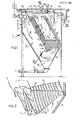
- the device 1 shown in Figures 1 and 2 for separating water 2 and water-insoluble, light substances 3 contained therein, for example, oil comprises a reservoir 4 for receiving a mixture 5 of water 2 and substances 3 and a plurality of sequential, parallel, sloping separation channels 6 arranged in the reservoir 4 and bounded by channel walls 7, an inlet chamber 9, a mixture inlet 8 opening out in the inlet chamber 9 and distributing the mixture at right angles to the plane of the drawing, a feeding chamber 20 communicating with the inlet chamber 9, a substance outlet 12, a layer-limit sensor 13, an overflow 14 with an overflow rim 15, a water outlet 16 communicating with the overflow 14 and a screen 18 separating the overflow 14 from a collecting space 17 for light substances 3.
- the assembly of separation channels 6 is arranged between the feeding chamber 20 and an outlet chamber 21 of the reservoir 4.
- the mixture flows through a dosing member 70, in which flocculation promoting chemicals are added to the mixture 5 and through a mixer 71 towards the mixture inlet 8.
- the desired flocculation takes place in the feeding chamber 20.
- the mixture 5 is passed towards the separation channels 6 through substance guide means 22, which evenly distribute the mixture 5 among the separation channels 6.
- the substance guiding means 22 are formed by gutters, which increase the flow resistance, viewed in the direction of disposition of the channels 6, the higher the nearer they are to the feeding chamber 20.
- Figure 1 shows that the foremost substance guiding means 22 are the longest and that they are shorter the further they are disposed to the rear in the direction 23. The chosen design of the substance guiding means 22 prevents the foremost channels 6 from passing proportionally more mixture 5.
- the inlet chamber 9 and the feeding chamber 20 are operating as pre-separators, since herein light substances 3 rise up into a collecting space 97, from which they are removed through a tap 98 and since herein heavy substances 38 settle down in a collecting space 39.
- the mixture 5 passes in the direction of the arrow 37 through the separation channels 6 at such a low rate that the light substance 3 and the heavy substances 38 drift towards the lower side and the top side respectively of the channel walls 7, along which they rise and fall respectively.
- the top ends of the channel walls 7 are provided with finger- and gutter-shaped substance guide means 40, which guide the light substances 3 towards the collecting space 17, whereas the lower ends of the channel walls 7 are provided with said substance guide means 22 for conducting the heavy substances 38 towards the collecting space 39.
- the substance guide means 40 and 22 leave free adequate space for passing water 2 and mixture 5 respectively.
- a mixture 5 of water 2 and substances 3 is guided in the direction of the arrow 37 through the plurality of separation channels 6 at such a low flow rate that under the action of gravity the substances 3 are urged to the lower sides of the channel walls 7, along which they are moved on in the direction of the arrow 37.
- the substances 3 are subsequently assembled via the substance guide means 40 into narrow streams, which reach the outlet chamber 21, in which they rise like rising droplet streams 26 into the collecting space 17.
- the substance outlet 12 is turned about an axis 29, for example, by means of a manually operated lever 80 for conducting away the substances 3.
- the purified water 2 flows via the overflow 14 towards the water outlet 16.
- the heavy substances 38 are conducted away by opening a closing member 43 of the collecting space 39.
- the (foremost) substance guide means 22 disposed nearest the feeding chamber 20 have the greater length.
- the foremost substance guide means 22 may have the same length as the further means but a larger width.
- the foremost substance guide means 22 are both longer and broader than the substance guide means 22 following the f b rmer.
- the reservoir 4 comprises a guide wall 75, which is at an obtuse angle u of, for example, 120° to the hindmost separation channels 6b. Therefore, the mixture 5 flows more readily in the hindmost separation channels 6 than in the foremost separation channels 6c.
- the mixture 5 flows in the feeding chamber 20 in the direction of the arrow 82 opposite the direction of flow 37 in the separation channels 6.
- the deflection required thereto indicated by arrows 76 impedes the inflow into the foremost separation channels 6c, which is an additional safeguard against an excessive quantity of flow in the channels 6c.
- the device 1 preferably has the form illustrated in Figure 1 with the associated ratios between the passages of separation channels 6, feeding chamber 20 and outlet chamber 21.
- the length 1 of the separation channels 6 is, for example, 180 cms and their width b is 5 cms., whilst twenty channels are disposed at the angle of inclination w of 600.
- the foremost substance guide means 22 has a length of 22 cms and the hindmost a length of 10 cms.
- the width r of the substance guide means 22 gradually decreases in downward direction, for example, in the manner illustrated in Figure 1.
Landscapes
- Chemical & Material Sciences (AREA)
- Chemical Kinetics & Catalysis (AREA)
- Physics & Mathematics (AREA)
- Thermal Sciences (AREA)
- Removal Of Floating Material (AREA)
- Water Treatment By Sorption (AREA)
Abstract
A device for treating waste water, wherein by gravitational segregation the waste water is separated from the water-insoluble substances contained therein, such as oil, comprises a stream trajectory, which accomodates a feeding chamber communicating with lower ends of separation channels. Therein the substance guide means extend transversely of the stream trajectory below the channels.
Since the overall flow space of the plate separator is passed in one and the same upward direction and because it is ensured that the flow rate in alle separation channels is substantially the same, a satisfactory gravitational segrata- tion is obtained owing to the comparatively low, uniform flow rate in alle separation channels.
Description
- The invention relates to a device for treating waste water, wherein by gravitational segregation the waste water is separated from the water-insoluble substances contained therein, such as oil, comprising a reservoir having a mixture inlet, a water outlet and at least one outlet for separated substances separated from the water outlet, which reservoir accommodates at least one stream trajectory including a plate separator having a plurality of parallel, sequential, flat separation channels bounded by separation plates and a feeding chamber communicating with lower ends of the separation cnannels and an outlet chamber communicating with top ends of the separation channels, whilst substance guide means joining the separation plates project transversely of the stream trajectory below the channels and increase the flow resistance in the direction of disposition of the channels the more so the nearer they are disposed to a feeding chamber.
- Such a device is known from US patent 367,308. In the known device the stream trajectory in the plate separator has a zigzag shape. For this purpose the stream trajectory is formed by a sequence of trajectory sections directed parallel to one another and alternately extending upwards and downwards and having a successively larger overall passage towards sucessively narrower separation channels. Although it is thus endeavoured to improve the separation by decreasing the flow rate in the last trajectory section, the flow rate in all trajectory sections and even in the last one is high.
- The invention provides a device of improved separation capacity and/or of smaller dimensions, since all separation channels communicate with their lower ends with one and the same inlet chamber, since all separation channels conduct mixture only in upward direction, since all separation channels have substantially equal passages and since the substance guide means and the angle between the separation plates on the one hand and a guide wall on the other hand are proportioned so that the quantity of flow in all separation channels is-substantially the same. Since the overall flow space of the plate separator is passed in one and the same upward direction and because it is ensured that the flow rate in all separation channels is substantially the same, a satisfactory gravitational segregation is obtained owing to the comparatively low, ·uniform flow rate in all separation channels.
- The aforesaid and further features of the invention will be explained more fully hereinafter with reference to examples.
- The drawing schematically shows in:
- Figure 1 a longitudinal sectional view of a preferred embodiment of a device in accordance with the invention, and
- Figure 2 a perspective view of detail II of Figure 1.
- The device 1 shown in Figures 1 and 2 for separating water 2 and water-insoluble, light substances 3 contained therein, for example, oil comprises a reservoir 4 for receiving a
mixture 5 of water 2 and substances 3 and a plurality of sequential, parallel,sloping separation channels 6 arranged in the reservoir 4 and bounded by channel walls 7, an inlet chamber 9, a mixture inlet 8 opening out in the inlet chamber 9 and distributing the mixture at right angles to the plane of the drawing, afeeding chamber 20 communicating with the inlet chamber 9, asubstance outlet 12, a layer-limit sensor 13, an overflow 14 with anoverflow rim 15, awater outlet 16 communicating with the overflow 14 and a screen 18 separating the overflow 14 from a collecting space 17 for light substances 3. The assembly ofseparation channels 6 is arranged between thefeeding chamber 20 and an outlet chamber 21 of the reservoir 4. - The mixture flows through a
dosing member 70, in which flocculation promoting chemicals are added to themixture 5 and through amixer 71 towards the mixture inlet 8. The desired flocculation takes place in thefeeding chamber 20. - In order to ensure that all
separation channels 6 pass substantially equal quantities, themixture 5 is passed towards theseparation channels 6 through substance guide means 22, which evenly distribute themixture 5 among theseparation channels 6. As shown in Figures 1 and 2 the substance guiding means 22 are formed by gutters, which increase the flow resistance, viewed in the direction of disposition of thechannels 6, the higher the nearer they are to thefeeding chamber 20. Figure 1 shows that the foremost substance guiding means 22 are the longest and that they are shorter the further they are disposed to the rear in thedirection 23. The chosen design of the substance guiding means 22 prevents theforemost channels 6 from passing proportionallymore mixture 5. - The inlet chamber 9 and the
feeding chamber 20 are operating as pre-separators, since herein light substances 3 rise up into acollecting space 97, from which they are removed through atap 98 and since herein heavy substances 38 settle down in acollecting space 39. Themixture 5 passes in the direction of thearrow 37 through theseparation channels 6 at such a low rate that the light substance 3 and the heavy substances 38 drift towards the lower side and the top side respectively of the channel walls 7, along which they rise and fall respectively. The top ends of the channel walls 7 are provided with finger- and gutter-shaped substance guide means 40, which guide the light substances 3 towards the collecting space 17, whereas the lower ends of the channel walls 7 are provided with said substance guide means 22 for conducting the heavy substances 38 towards thecollecting space 39. The substance guide means 40 and 22 leave free adequate space for passing water 2 andmixture 5 respectively. - In the device 1 of Figure 1 a
mixture 5 of water 2 and substances 3 is guided in the direction of thearrow 37 through the plurality ofseparation channels 6 at such a low flow rate that under the action of gravity the substances 3 are urged to the lower sides of the channel walls 7, along which they are moved on in the direction of thearrow 37. The substances 3 are subsequently assembled via the substance guide means 40 into narrow streams, which reach the outlet chamber 21, in which they rise like rising droplet streams 26 into the collecting space 17. - When the layer-limit sensor 13 indicates that substance 3 is present at the
level 28, thesubstance outlet 12 is turned about anaxis 29, for example, by means of a manually operatedlever 80 for conducting away the substances 3. - The purified water 2 flows via the overflow 14 towards the
water outlet 16. - The heavy substances 38 are conducted away by opening a
closing member 43 of thecollecting space 39. - As shown in Figure 1 the (foremost) substance guide means 22 disposed nearest the
feeding chamber 20 have the greater length. As an alternative, the foremost substance guide means 22 may have the same length as the further means but a larger width. Preferably the foremost substance guide means 22 are both longer and broader than the substance guide means 22 following the fbrmer. The reservoir 4 comprises aguide wall 75, which is at an obtuse angle u of, for example, 120° to the hindmost separation channels 6b. Therefore, themixture 5 flows more readily in thehindmost separation channels 6 than in theforemost separation channels 6c. Themixture 5 flows in thefeeding chamber 20 in the direction of thearrow 82 opposite the direction offlow 37 in theseparation channels 6. The deflection required thereto indicated by arrows 76 impedes the inflow into theforemost separation channels 6c, which is an additional safeguard against an excessive quantity of flow in thechannels 6c. - The device 1 preferably has the form illustrated in Figure 1 with the associated ratios between the passages of
separation channels 6,feeding chamber 20 and outlet chamber 21. The length 1 of theseparation channels 6 is, for example, 180 cms and their width b is 5 cms., whilst twenty channels are disposed at the angle of inclination w of 600. The foremost substance guide means 22 has a length of 22 cms and the hindmost a length of 10 cms. The width r of the substance guide means 22 gradually decreases in downward direction, for example, in the manner illustrated in Figure 1.
Claims (1)
- A device for treating waste water, wherein by gravitational segregation the waste water is separated from the water-insoluble substances contained therein, such as oil, comprising a reservoir having a mixture inlet, a water outlet and at least one outlet for separated substances separated from the water outlet, which reservoir accommodates at least one stream trajectory including a plate separator having a plurality of parallel, sequential, flat separation channels bounded by separation plates and a feeding chamber communicating with lower ends of the separation channels and an outlet chamber communicating with top ends of the separation channels, whilst substance guide means joining the separation plates project transversely of the stream trajectory below the channels and increase the flow resistance in the direction of disposition of the channels the more so the nearer they are disposed to a feecing chamber, characterized in that all separation channels communicate by their lower ends with one and the same feeding chamber, in that all separation channels conduct mixture only in upward direction, in that all separation channels have substantially equal passages and in that the substance guide means and the angle between the separation plates on the one hand and a guide wall on the other hand are proportioned so that the quantity of flow in all separation channels is substantially the same.
Applications Claiming Priority (2)
| Application Number | Priority Date | Filing Date | Title |
|---|---|---|---|
| NL7800180A NL7800180A (en) | 1978-01-06 | 1978-01-06 | DEVICE FOR THE SEPARATION OF WATER AND SUBSTANCES THEREOF. |
| NL7800180 | 1978-01-06 |
Publications (2)
| Publication Number | Publication Date |
|---|---|
| EP0003146A2 true EP0003146A2 (en) | 1979-07-25 |
| EP0003146A3 EP0003146A3 (en) | 1979-08-08 |
Family
ID=19830102
Family Applications (1)
| Application Number | Title | Priority Date | Filing Date |
|---|---|---|---|
| EP79200008A Withdrawn EP0003146A3 (en) | 1978-01-06 | 1979-01-05 | A device for treating waste water by gravitational segregation |
Country Status (2)
| Country | Link |
|---|---|
| EP (1) | EP0003146A3 (en) |
| NL (1) | NL7800180A (en) |
Cited By (7)
| Publication number | Priority date | Publication date | Assignee | Title |
|---|---|---|---|---|
| DE4231790A1 (en) * | 1992-09-23 | 1994-03-24 | M Dr Rer Nat Fariwar | Vehicle washing station waste water cleaning - has angled blades for water to flow upwards to separate floating matter |
| WO1994026384A1 (en) * | 1993-05-07 | 1994-11-24 | Bioscot Limited | Particle settler for use in cell culture |
| BE1007667A3 (en) * | 1993-10-29 | 1995-09-12 | Etangs Gehlen Sprl | E.B.E. multi-stage biological purification system |
| WO1995029877A1 (en) * | 1994-04-28 | 1995-11-09 | Tord Georg Eriksson | Water- and chemical recycling |
| RU2158233C1 (en) * | 1999-11-18 | 2000-10-27 | Друцкий Алексей Васильевич | Plant for purification of storm waste water |
| EP1364694A1 (en) * | 2002-05-16 | 2003-11-26 | Betonwerk Nageler Gesellschaft m.b.H. | Process and apparatus to form grease deposit |
| WO2012098055A1 (en) | 2011-01-17 | 2012-07-26 | F. Hoffmann-La Roche Ag | Separation apparatus and use thereof |
Family Cites Families (2)
| Publication number | Priority date | Publication date | Assignee | Title |
|---|---|---|---|---|
| US367308A (en) * | 1887-07-26 | Signob to said william macnab | ||
| NL7604390A (en) * | 1976-04-23 | 1977-10-25 | Ballast Nedam Groep Nv | METHOD AND EQUIPMENT FOR THE SEPARATION OF WATER INTO SUBSTANCES THEREIN. |
-
1978
- 1978-01-06 NL NL7800180A patent/NL7800180A/en not_active Application Discontinuation
-
1979
- 1979-01-05 EP EP79200008A patent/EP0003146A3/en not_active Withdrawn
Cited By (16)
| Publication number | Priority date | Publication date | Assignee | Title |
|---|---|---|---|---|
| DE4231790A1 (en) * | 1992-09-23 | 1994-03-24 | M Dr Rer Nat Fariwar | Vehicle washing station waste water cleaning - has angled blades for water to flow upwards to separate floating matter |
| DE4231790B4 (en) * | 1992-09-23 | 2006-10-05 | Fariwar-Mohseni, Ursula | Apparatus for the treatment of waste water |
| AU691494B2 (en) * | 1993-05-07 | 1998-05-21 | Millipore (U.K.) Limited | Particle settler for use in cell culture |
| WO1994026384A1 (en) * | 1993-05-07 | 1994-11-24 | Bioscot Limited | Particle settler for use in cell culture |
| BE1007667A3 (en) * | 1993-10-29 | 1995-09-12 | Etangs Gehlen Sprl | E.B.E. multi-stage biological purification system |
| WO1995029877A1 (en) * | 1994-04-28 | 1995-11-09 | Tord Georg Eriksson | Water- and chemical recycling |
| US5827373A (en) * | 1994-04-28 | 1998-10-27 | Eriksson; Tord Georg | Water-and chemical recycling |
| RU2158233C1 (en) * | 1999-11-18 | 2000-10-27 | Друцкий Алексей Васильевич | Plant for purification of storm waste water |
| EP1364694A1 (en) * | 2002-05-16 | 2003-11-26 | Betonwerk Nageler Gesellschaft m.b.H. | Process and apparatus to form grease deposit |
| WO2012098055A1 (en) | 2011-01-17 | 2012-07-26 | F. Hoffmann-La Roche Ag | Separation apparatus and use thereof |
| JP2014502511A (en) * | 2011-01-17 | 2014-02-03 | エフ.ホフマン−ラ ロシュ アーゲー | Separation device and use thereof |
| JP2017006139A (en) * | 2011-01-17 | 2017-01-12 | エフ.ホフマン−ラ ロシュ アーゲーF. Hoffmann−La Roche Aktiengesellschaft | Separation apparatus and use thereof |
| US10702800B2 (en) | 2011-01-17 | 2020-07-07 | Hoffman-La Roche Inc. | Separation apparatus and use thereof |
| EP4036207A1 (en) | 2011-01-17 | 2022-08-03 | F. Hoffmann-La Roche AG | Use of a separation apparatus in a seed train |
| US11697079B2 (en) | 2011-01-17 | 2023-07-11 | Hoffmann-La Roche Inc. | Separation apparatus and use thereof |
| US12274960B2 (en) | 2011-01-17 | 2025-04-15 | Hoffman-La Roche Inc. | Separation apparatus and use thereof |
Also Published As
| Publication number | Publication date |
|---|---|
| EP0003146A3 (en) | 1979-08-08 |
| NL7800180A (en) | 1979-07-10 |
Similar Documents
| Publication | Publication Date | Title |
|---|---|---|
| US4202778A (en) | Separating device | |
| US6537458B1 (en) | Three-phase separator | |
| US3346122A (en) | Plate separator with drainage gutter | |
| CA2085693C (en) | Lateral flow coalescing multiphase separator | |
| CA1161370A (en) | Method and apparatus for supplying and distrubuting composite liquids to a laminar separation apparatus | |
| CA1090262A (en) | Vertical tube liquid pollutant separator | |
| US4056477A (en) | Separating apparatus for clarifying liquid | |
| US5173195A (en) | Phase separator module | |
| US3529728A (en) | Oil separating device | |
| KR100232762B1 (en) | Sedimentation apparatus for fluids containing liquids, gases and particulates, wastewater purification apparatus and method for purification | |
| WO2000051707A9 (en) | Three-phase separator | |
| US20130276416A1 (en) | Drained coalescer | |
| CA1091590A (en) | Device for separating water from substances contained therein | |
| US1493861A (en) | Separation of solids from liquids | |
| US4213865A (en) | Apparatus for separating sludge, oil and the like from contaminated water | |
| US367308A (en) | Signob to said william macnab | |
| CA2687923C (en) | Flotation apparatus with apertured plate | |
| US5588912A (en) | Sieve for harvesting machines | |
| CZ313494A3 (en) | Sludge and oil separator | |
| CA2810314C (en) | Separator for separating a light liquid-water mixture and method for separating a light liquid-water mixture | |
| US4113629A (en) | Separation device provided with a coalescence apparatus | |
| US5658461A (en) | Sedimentation apparatus | |
| US397585A (en) | Combined separator and concentrator | |
| FI56319C (en) | ANORDNING FOER SEPARERING AV SUSPENDERADE FASTA PARTIKLAR UR EN VAETSKESTROEM | |
| EP1270055A2 (en) | Sludge und oil separator for waste water |
Legal Events
| Date | Code | Title | Description |
|---|---|---|---|
| PUAI | Public reference made under article 153(3) epc to a published international application that has entered the european phase |
Free format text: ORIGINAL CODE: 0009012 |
|
| PUAL | Search report despatched |
Free format text: ORIGINAL CODE: 0009013 |
|
| AK | Designated contracting states |
Designated state(s): BE CH DE FR GB IT LU NL SE |
|
| AK | Designated contracting states |
Designated state(s): BE CH DE FR GB IT LU NL SE |
|
| 17P | Request for examination filed | ||
| STAA | Information on the status of an ep patent application or granted ep patent |
Free format text: STATUS: THE APPLICATION IS DEEMED TO BE WITHDRAWN |
|
| 18D | Application deemed to be withdrawn |
Effective date: 19810930 |
|
| RIN1 | Information on inventor provided before grant (corrected) |
Inventor name: LINDENBERGH, HANS Inventor name: MIDDELBEEK, CORNELIS GERARDUS |