EP0001481B1 - Variable load valve apparatus with load independent initial pressure output in a braking system - Google Patents
Variable load valve apparatus with load independent initial pressure output in a braking system Download PDFInfo
- Publication number
- EP0001481B1 EP0001481B1 EP78300380A EP78300380A EP0001481B1 EP 0001481 B1 EP0001481 B1 EP 0001481B1 EP 78300380 A EP78300380 A EP 78300380A EP 78300380 A EP78300380 A EP 78300380A EP 0001481 B1 EP0001481 B1 EP 0001481B1
- Authority
- EP
- European Patent Office
- Prior art keywords
- valve
- pressure
- variable load
- piston
- area
- Prior art date
- Legal status (The legal status is an assumption and is not a legal conclusion. Google has not performed a legal analysis and makes no representation as to the accuracy of the status listed.)
- Expired
Links
- 239000012530 fluid Substances 0.000 claims description 9
- 230000001419 dependent effect Effects 0.000 claims description 6
- 230000000694 effects Effects 0.000 description 3
- 238000013022 venting Methods 0.000 description 3
- 230000001627 detrimental effect Effects 0.000 description 1
- 238000004519 manufacturing process Methods 0.000 description 1
Images

Classifications
-
- B—PERFORMING OPERATIONS; TRANSPORTING
- B60—VEHICLES IN GENERAL
- B60T—VEHICLE BRAKE CONTROL SYSTEMS OR PARTS THEREOF; BRAKE CONTROL SYSTEMS OR PARTS THEREOF, IN GENERAL; ARRANGEMENT OF BRAKING ELEMENTS ON VEHICLES IN GENERAL; PORTABLE DEVICES FOR PREVENTING UNWANTED MOVEMENT OF VEHICLES; VEHICLE MODIFICATIONS TO FACILITATE COOLING OF BRAKES
- B60T8/00—Arrangements for adjusting wheel-braking force to meet varying vehicular or ground-surface conditions, e.g. limiting or varying distribution of braking force
- B60T8/18—Arrangements for adjusting wheel-braking force to meet varying vehicular or ground-surface conditions, e.g. limiting or varying distribution of braking force responsive to vehicle weight or load, e.g. load distribution
- B60T8/1812—Arrangements for adjusting wheel-braking force to meet varying vehicular or ground-surface conditions, e.g. limiting or varying distribution of braking force responsive to vehicle weight or load, e.g. load distribution characterised by the means for pressure reduction
- B60T8/1825—Means for changing the diaphragm area submitted to pressure
Definitions
- This invention relates to variable load valve apparatus and braking systems with inshot and relates especially but not exclusively to a braking system employing a variable load valve for adjusting the degree of braking in a road vehicle dependent upon the loading of the vehicle.
- load- proportioning valve means which operate in accordance with a signal related to the load carried by the vehicle for proportioning in accordance with load the pressure delivered to vehicle brake actuators from or in response to brake valve output.
- the pressure delivered may be low in relation to the force needed to overcome the return springs and frictional resistance in the actuators and it has been proposed to provide "inshot" pressure in such a system whereby an initial load-independent component of pressure is produced up to a given value of pressure.
- German Offenlegungsschrift 27 24 945 describes such a variable load valve apparatus which has graduating means operable after the attainment of the said given value of pressure to progressively remove the load-independent component of pressure as the output pressure is further increased.
- variable load valve apparatus for a fluid pressure vehicle braking system including a variable load valve for adjusting the ratio of fluid pressure at an output port in relation to fluid pressure at an input port in accordance with a load-dependent input, the apparatus also including further valve means operable to provide a further input pressure to the variable load valve to cause said variable load valve to produce an initial pressure output independent of the load-dependent input up to a predetermined value of the further input, the further valve means including a double valve controlled by a biassed pressure- responsive means having a first area acted upon by the further pressure and a second area acted upon by a braking pressure signal characterised in that the second area is an area of substantially smaller periphery than the first area.
- variable load valve is constructed with upper and lower body members denoted by references 1 and 2 respectively and which are bolted together to include a control piston 3, a flexible diaphragm 4 and a valve arrangement comprising a springloaded valve member 5 which normally engages against a seat 6 and is further engageable by an internal tubular member 7 which is sealingly slideable in the lower body member and is engageable in turn with a ball pivot 8 carried by a pivoted lever 9 positioned by vehicle load.
- the member 7 is clamped when a brake application is made, by virtue of pressure being applied beneath a piston 10 in a cylinder 11 which is connected via an external pipe 12 to the brake supply input port 13 which is above the normally closed valve 5.
- the control piston 3 carries radially extending fingers such as the finger 14 which move between corresponding fingers 28 against which the diaphragm rests in the position shown, the arrangement being such that on downward movement of the piston, the diaphragm is increasingly engaged by the radial fingers 14 and decreasingly engaged by the inwardly projecting fins 28 such that the effect of pressure beneath the diaphragm on the piston arrangement, increases the greater the downward deflection of the piston.
- radially extending fingers such as the finger 14 which move between corresponding fingers 28 against which the diaphragm rests in the position shown
- a further port is connected to the region of the body of the variable load valve which is above the diaphragm 4 and this port, denoted by reference 15, is connected to an output port 31 of the inshot valve.
- the inshot valve has a supply and control input port reference 32.
- the inshot valve itself includes a piston 33, with a pressure responsive area 44 having a downwardly extending valve part 42, and is biassed downwards by a spring 34 against the upward force created by pressure at port 31 and by the thrust of a light spring 35 acting on a valve member 36.
- the valve member 36 forms part of a double valve and can seat against an input valve seat 37 and an exhaust valve seat 38 carried by valve part 42, the output side of which communicates with atmosphere via a central bore 39.
- a piston 41 which is sealingly slideable within the sleeve of valve 36 which forms a cylinder for the piston 41 which has a smaller pressure responsive area 43.
- the periphery of the piston 41 which is subjected to the pressure applied at the input port 32, is only a fraction of the periphery of the piston 33 which is. subjected to the output pressure presented via port 31.
- variable load valve receives a brake pressure at port 13 from a reservoir via a driver's brake valve which is usually a foot-operated valve.
- the pressure delivered at the port 27 is applied to the brake actuators and in the case of there also being a trailer vehicle, possibly to a relay valve which controls trailer service brakes.
- variable load valve when a brake application is made, air at the supply pressure is applied via the input port 13 to the chamber above the valve 5 causing downward deflection of the piston 3. At the same time, there is a flow of air from the port 13 to the cylinder 11 so that the piston 10 is upwardly deflected to clamp the ball pivot against the internally slideable stem 7 by virtue of which the movable parts within the arrangement are responsive only when braking pressures are supplied and thereby avoiding unnecessary wear. Since the valve is supported by the tubular stem 7, downward deflection of the piston 3 unseats the valve 5 from its seat 6, permitting brake supply air to pass to the brake actuators via the variable load valve output port denoted by reference 27.
- this pressure is presented to the region beneath the diaphragm 4 by a passage which is not readily seen in the drawing.
- the diaphragm moves away from the fixed support of the inwardly directed fingers carried by the housing and becomes the more partially supported by the fingers such as 14 carried by the piston.
- This modifies the effective area of the diaphragm supported by the moving piston until the force beneath the diaphragm which depends upon the pressure and effective area, equalises with the force acting above the piston.
- the valve 5 reseats with seat 6 and a balance is achieved with a lower pressure at 27 than that which is applied at 13, keeping the valve assembly in the lapped condition with the input and exhaust ways via the valve 5 closed.
- the pressure which this has obtained depends upon the position of the lever 9 and therefore upon the loading of the vehicle.
- the pressure in the port 27, which is applied to the brake actuators lifts the piston, thereby unseating the valve 5 from the internal tubular stem 7 to result in venting of the pressure from 27 to atmosphere through the centre of the tube 7 until a pressure is re-achieved or total release is obtained.
- valve member 36 With increasing pressure from the foot valve at the input port 32, whilst the communication between the area of the valve 33 and input port 32 has been closed off by the seating of the valve member 36 on the seat 37, the area 43 of the piston 41 continues to be in communication with the input port 32 and on further deflection of the spring 34, the pressure in the chamber 28 above the diaphragm of the variable load valve, is progressively vented by the unseating of valve seat 38 with the. valve member 36.
- the valve member 36 and seats 37 and 38 therefore operate as a self-lapping double valve and the pressure at port 31 is progressively reduced with increasing supply pressure from the brake valve.
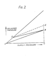
- curve ADB is a typical representation of the relationship of the delivered pressure at port 27 relative to the supply pressure at port 13 from the driver's brake valve for a given load setting of the variable load valve.
- the further pressure at the port 31 gives rise to pressure corresponding to the portion AD of the graph shown in Fig. 2 which is independent of the load setting.
- the output of the port 27 varies thereafter with supply pressure according to portion DB of the curve.
- the point B is the point corresponding to load-proportioned supply pressure achieved by virtue of the graduable venting of the initial further pressure above the diaphragm of the variable load valve over the range of operation following the point D.
- the curve ADE illustrates the output which would occur in the event that the further pressure above the diaphragm 4 were not so graduably removed but maintained through the range of operation.
- the reduction of the effective ratio of the variable load valve especially for light loads, which can result without the said graduable venting is therefore quite appreciable.
- the further valve which is operable to provide an initial range of pressure output independent of the load-dependent signal, (namely, the position taken up by the lever 9) receives the variable load valve input pressure to cause the inshot component at port 15 to be progressively reduced as described above.
- an alternative pressure instead of the variable load valve input
- the delivered pressure of the variable load valve at port 27 may be used to cause this graduable reduction of the further pressure. It will be understood that appropriate adjustment of the relative dimensions of the piston 33 and the piston 41 of the further valve may be required.
- the further valve which is called an inshot valve therein may be arranged to receive a pressure other than that which is presented to the input of the variable load valve. It is stated for example that the pressure which appears at the output of the variable load valve may itself be used as an input to the inshot valve, it being understood that appropriate adjustments of the dimensions of the piston may be required.
- the input port 32 may be arranged to derive its input pressure from the delivery port 27 of the variable load valve.
- the further pressure which is applied in the variable load valve above the variable effective area diaphragm is represented as being graduably released up to the point B of full braking. If desired, this may be arranged to occur at an earlier point on the characteristic of Fig. 2 by reducing the effective area of the piston 41 in relation to that of piston 33.
- variable load valve Whilst in the foregoing, the operation of the variable load valve has been described in the context of a single or tractor vehicle, the variable load valve may be employed on a trailer or semi-trailer vehicle and be supplied with fluid pressure from a trailer service brake control line when connected to a tractor and thereby control the tractor brakes in dependence upon load.
Landscapes
- Engineering & Computer Science (AREA)
- Transportation (AREA)
- Mechanical Engineering (AREA)
- Hydraulic Control Valves For Brake Systems (AREA)
- Valves And Accessory Devices For Braking Systems (AREA)
Description
- This invention relates to variable load valve apparatus and braking systems with inshot and relates especially but not exclusively to a braking system employing a variable load valve for adjusting the degree of braking in a road vehicle dependent upon the loading of the vehicle.
- In fluid operable vehicle braking systems it has been proposed to employ load- proportioning valve means which operate in accordance with a signal related to the load carried by the vehicle for proportioning in accordance with load the pressure delivered to vehicle brake actuators from or in response to brake valve output.
- In such a system, operating under light load conditions, the pressure delivered may be low in relation to the force needed to overcome the return springs and frictional resistance in the actuators and it has been proposed to provide "inshot" pressure in such a system whereby an initial load-independent component of pressure is produced up to a given value of pressure.
- The Specification of German Offenlegungsschrift 27 24 945 describes such a variable load valve apparatus which has graduating means operable after the attainment of the said given value of pressure to progressively remove the load-independent component of pressure as the output pressure is further increased.
- By providing such graduating means, the advantage is gained that, especially for low values of load, the provision of such inshot pressure is less detrimental to the effective operating ratio of the variable load valve apparatus.
- However, the apparatus described in the said German Offenlegungsschrift has been found to lack a desired degree of precision of operation and is highly susceptible to manufacturing tolerances.
- The present invention provides variable load valve apparatus for a fluid pressure vehicle braking system including a variable load valve for adjusting the ratio of fluid pressure at an output port in relation to fluid pressure at an input port in accordance with a load-dependent input, the apparatus also including further valve means operable to provide a further input pressure to the variable load valve to cause said variable load valve to produce an initial pressure output independent of the load-dependent input up to a predetermined value of the further input, the further valve means including a double valve controlled by a biassed pressure- responsive means having a first area acted upon by the further pressure and a second area acted upon by a braking pressure signal characterised in that the second area is an area of substantially smaller periphery than the first area.
- In order that the invention may be more clearly understood and readly carried into effect, the same will be further described by way of example, with reference to the accompanying drawings, of which:-
- Fig. 1 illustrates in diagrammatical form a variable load valve of known form, together with an inshot valve connected to the variable load valve to enable the variable load valve to provide inshot and
- Fig. 2 illustrates graphically the effect on the variable load valve output of inshot employing an inshot valve in accordance with the present invention.
- Referring to the drawing, the variable load valve is constructed with upper and lower body members denoted by
references 1 and 2 respectively and which are bolted together to include a control piston 3, a flexible diaphragm 4 and a valve arrangement comprising a springloaded valve member 5 which normally engages against a seat 6 and is further engageable by an internal tubular member 7 which is sealingly slideable in the lower body member and is engageable in turn with aball pivot 8 carried by apivoted lever 9 positioned by vehicle load. The member 7 is clamped when a brake application is made, by virtue of pressure being applied beneath apiston 10 in acylinder 11 which is connected via anexternal pipe 12 to the brakesupply input port 13 which is above the normally closed valve 5. The control piston 3 carries radially extending fingers such as thefinger 14 which move betweencorresponding fingers 28 against which the diaphragm rests in the position shown, the arrangement being such that on downward movement of the piston, the diaphragm is increasingly engaged by theradial fingers 14 and decreasingly engaged by the inwardly projecting fins 28 such that the effect of pressure beneath the diaphragm on the piston arrangement, increases the greater the downward deflection of the piston. A similar such arrangement is previously described in the Specification of British Patent No. 1029183 and need not be further described herein. - Referring now to the further valve arrangement which may be referred to as an inshot valve, for the purposes of connecting this to the variable load valve, a further port is connected to the region of the body of the variable load valve which is above the diaphragm 4 and this port, denoted by
reference 15, is connected to anoutput port 31 of the inshot valve. Additionally, the inshot valve has a supply and controlinput port reference 32. The inshot valve itself includes apiston 33, with a pressureresponsive area 44 having a downwardly extendingvalve part 42, and is biassed downwards by aspring 34 against the upward force created by pressure atport 31 and by the thrust of alight spring 35 acting on avalve member 36. Thevalve member 36 forms part of a double valve and can seat against aninput valve seat 37 and anexhaust valve seat 38 carried byvalve part 42, the output side of which communicates with atmosphere via acentral bore 39. Mechanically engageable via arod 40 with thepart 42, there is apiston 41 which is sealingly slideable within the sleeve ofvalve 36 which forms a cylinder for thepiston 41 which has a smaller pressureresponsive area 43. The periphery of thepiston 41 which is subjected to the pressure applied at theinput port 32, is only a fraction of the periphery of thepiston 33 which is. subjected to the output pressure presented viaport 31. - Whilst not shown in the drawing, the variable load valve receives a brake pressure at
port 13 from a reservoir via a driver's brake valve which is usually a foot-operated valve. The pressure delivered at theport 27 is applied to the brake actuators and in the case of there also being a trailer vehicle, possibly to a relay valve which controls trailer service brakes. - Referring briefly to the operation of the variable load valve itself, when a brake application is made, air at the supply pressure is applied via the
input port 13 to the chamber above the valve 5 causing downward deflection of the piston 3. At the same time, there is a flow of air from theport 13 to thecylinder 11 so that thepiston 10 is upwardly deflected to clamp the ball pivot against the internally slideable stem 7 by virtue of which the movable parts within the arrangement are responsive only when braking pressures are supplied and thereby avoiding unnecessary wear. Since the valve is supported by the tubular stem 7, downward deflection of the piston 3 unseats the valve 5 from its seat 6, permitting brake supply air to pass to the brake actuators via the variable load valve output port denoted byreference 27. At the same time, this pressure is presented to the region beneath the diaphragm 4 by a passage which is not readily seen in the drawing. Furthermore, as the piston is downwardly deflected, the diaphragm moves away from the fixed support of the inwardly directed fingers carried by the housing and becomes the more partially supported by the fingers such as 14 carried by the piston. This modifies the effective area of the diaphragm supported by the moving piston until the force beneath the diaphragm which depends upon the pressure and effective area, equalises with the force acting above the piston. At this point, the valve 5 reseats with seat 6 and a balance is achieved with a lower pressure at 27 than that which is applied at 13, keeping the valve assembly in the lapped condition with the input and exhaust ways via the valve 5 closed. The pressure which this has obtained depends upon the position of thelever 9 and therefore upon the loading of the vehicle. When the brakes are released, the pressure in theport 27, which is applied to the brake actuators, lifts the piston, thereby unseating the valve 5 from the internal tubular stem 7 to result in venting of the pressure from 27 to atmosphere through the centre of the tube 7 until a pressure is re-achieved or total release is obtained. - In the foregoing, the fact of a further input pressure applied from the further valve to above the diaphragm 4, has been ignored for the sake of initial understanding. With increasing supply pressure at the
input port 32 of the inshot valve starting from a zero pressure, an identical increase of output pressure occurs by virtue of the communication betweenport 32 andport 31 via theuncovered valve seat 37. With increasing such pressure, acting both on thearea 43 of thepiston 41 and thearea 42 of thepiston 33, thebias spring 34 is progressively deflected up to a predetermined value of input pressure at which thevalve member 36 seats against thevalve seat 37. This determines the amount of initial fluid pressure into the brake actuators which can occur quite independently of the operation of the variable load valve. Following this point, with increasing pressure from the foot valve at theinput port 32, whilst the communication between the area of thevalve 33 andinput port 32 has been closed off by the seating of thevalve member 36 on theseat 37, thearea 43 of thepiston 41 continues to be in communication with theinput port 32 and on further deflection of thespring 34, the pressure in thechamber 28 above the diaphragm of the variable load valve, is progressively vented by the unseating ofvalve seat 38 with the.valve member 36. Thevalve member 36 andseats port 31 is progressively reduced with increasing supply pressure from the brake valve. - In the graphical illustration in Fig. 2, curve ADB is a typical representation of the relationship of the delivered pressure at
port 27 relative to the supply pressure atport 13 from the driver's brake valve for a given load setting of the variable load valve. The further pressure at theport 31, gives rise to pressure corresponding to the portion AD of the graph shown in Fig. 2 which is independent of the load setting. For a given value of load, and therefore of position of thelever 9, the output of theport 27 varies thereafter with supply pressure according to portion DB of the curve. The point B is the point corresponding to load-proportioned supply pressure achieved by virtue of the graduable venting of the initial further pressure above the diaphragm of the variable load valve over the range of operation following the point D. For the purpose of comparison, the curve ADE illustrates the output which would occur in the event that the further pressure above the diaphragm 4 were not so graduably removed but maintained through the range of operation. The reduction of the effective ratio of the variable load valve especially for light loads, which can result without the said graduable venting is therefore quite appreciable. - In the foregoing, the further valve which is operable to provide an initial range of pressure output independent of the load-dependent signal, (namely, the position taken up by the lever 9) receives the variable load valve input pressure to cause the inshot component at
port 15 to be progressively reduced as described above. Nevertheless, it may be appreciated that as in the case of the apparatus or system as described in the abovementioned German Offenlegungsschrift, an alternative pressure (instead of the variable load valve input) may be applied to such a further valve to achieve a similar result. For example, the delivered pressure of the variable load valve atport 27 may be used to cause this graduable reduction of the further pressure. It will be understood that appropriate adjustment of the relative dimensions of thepiston 33 and thepiston 41 of the further valve may be required. - In the Specification of the aforementioned German Offenlegungsschrift it is stated that the further valve which is called an inshot valve therein may be arranged to receive a pressure other than that which is presented to the input of the variable load valve. It is stated for example that the pressure which appears at the output of the variable load valve may itself be used as an input to the inshot valve, it being understood that appropriate adjustments of the dimensions of the piston may be required. In a similar manner, in the case of the further valve of the present invention, the
input port 32 may be arranged to derive its input pressure from thedelivery port 27 of the variable load valve. - Again, in Fig. 2, the further pressure which is applied in the variable load valve above the variable effective area diaphragm, is represented as being graduably released up to the point B of full braking. If desired, this may be arranged to occur at an earlier point on the characteristic of Fig. 2 by reducing the effective area of the
piston 41 in relation to that ofpiston 33. - Whilst in the foregoing, the operation of the variable load valve has been described in the context of a single or tractor vehicle, the variable load valve may be employed on a trailer or semi-trailer vehicle and be supplied with fluid pressure from a trailer service brake control line when connected to a tractor and thereby control the tractor brakes in dependence upon load.
Claims (5)
Applications Claiming Priority (2)
| Application Number | Priority Date | Filing Date | Title |
|---|---|---|---|
| GB4067077 | 1977-09-30 | ||
| GB40670/77A GB1595195A (en) | 1977-09-30 | 1977-09-30 | Braking apparatus with inshot |
Publications (2)
| Publication Number | Publication Date |
|---|---|
| EP0001481A1 EP0001481A1 (en) | 1979-04-18 |
| EP0001481B1 true EP0001481B1 (en) | 1982-07-07 |
Family
ID=10416046
Family Applications (1)
| Application Number | Title | Priority Date | Filing Date |
|---|---|---|---|
| EP78300380A Expired EP0001481B1 (en) | 1977-09-30 | 1978-09-13 | Variable load valve apparatus with load independent initial pressure output in a braking system |
Country Status (5)
| Country | Link |
|---|---|
| EP (1) | EP0001481B1 (en) |
| AU (1) | AU518737B2 (en) |
| DE (1) | DE2861940D1 (en) |
| GB (1) | GB1595195A (en) |
| IT (1) | IT1109565B (en) |
Cited By (1)
| Publication number | Priority date | Publication date | Assignee | Title |
|---|---|---|---|---|
| WO2022084119A1 (en) | 2020-10-22 | 2022-04-28 | Basf Coatings Gmbh | Coating composition comprising an alkali salt of graphene oxide and coating layers produced from said coating composition |
Families Citing this family (2)
| Publication number | Priority date | Publication date | Assignee | Title |
|---|---|---|---|---|
| DE2722524A1 (en) * | 1977-05-18 | 1978-11-30 | Bosch Gmbh Robert | LOAD-DEPENDENT BRAKE PRESSURE REGULATOR FOR VEHICLES |
| DE3173719D1 (en) * | 1980-10-01 | 1986-03-20 | Bendix Ltd | Variable pressure ratio valve |
Family Cites Families (2)
| Publication number | Priority date | Publication date | Assignee | Title |
|---|---|---|---|---|
| US3404922A (en) * | 1967-03-23 | 1968-10-08 | Bendix Westinghouse Automotive | Brake balancing valve with brake tare compensating means |
| GB1585108A (en) * | 1976-06-08 | 1981-02-25 | Bendix Westinghouse Ltd | Braking apparatus with inshot |
-
1977
- 1977-09-30 GB GB40670/77A patent/GB1595195A/en not_active Expired
-
1978
- 1978-09-13 DE DE7878300380T patent/DE2861940D1/en not_active Expired
- 1978-09-13 EP EP78300380A patent/EP0001481B1/en not_active Expired
- 1978-09-20 AU AU40020/78A patent/AU518737B2/en not_active Expired
- 1978-09-29 IT IT69249/78A patent/IT1109565B/en active
Cited By (1)
| Publication number | Priority date | Publication date | Assignee | Title |
|---|---|---|---|---|
| WO2022084119A1 (en) | 2020-10-22 | 2022-04-28 | Basf Coatings Gmbh | Coating composition comprising an alkali salt of graphene oxide and coating layers produced from said coating composition |
Also Published As
| Publication number | Publication date |
|---|---|
| IT7869249A0 (en) | 1978-09-29 |
| EP0001481A1 (en) | 1979-04-18 |
| IT1109565B (en) | 1985-12-23 |
| GB1595195A (en) | 1981-08-12 |
| DE2861940D1 (en) | 1982-08-26 |
| AU4002078A (en) | 1980-03-27 |
| AU518737B2 (en) | 1981-10-15 |
Similar Documents
| Publication | Publication Date | Title |
|---|---|---|
| US2950147A (en) | Load compensating brake control apparatus for railway cars | |
| US3992065A (en) | Brake control valve device for fluid pressure operable dual brake systems for motor vehicles | |
| US3125379A (en) | valentine | |
| US4125290A (en) | Vehicle load-controlled brake pressure regulating valve device | |
| US4012079A (en) | Brake control apparatus actuated by sensing the deceleration of a vehicle | |
| US4145089A (en) | Vehicle load-controlled brake pressure regulating valve device | |
| US4418965A (en) | Load-controlled brake pressure control unit | |
| GB1585108A (en) | Braking apparatus with inshot | |
| US3945689A (en) | Combined load-sensing proportion and relay valve | |
| US4040673A (en) | Fluid pressure operable brake apparatus with load-compensating means for vehicles with tandem rear axles | |
| GB2069643A (en) | Deceleration sensing valves for vehicle brake proportioning valves | |
| US4679594A (en) | Two-circuit fluid pressure control valve | |
| EP0001481A1 (en) | Variable load valve apparatus with load independent initial pressure output in a braking system | |
| US4786116A (en) | Trailer control valve device for the trailer brakes of a tractor-trailer vehicle | |
| US3068050A (en) | Tractor-trailer air brake apparatus | |
| US3018139A (en) | Pressure control mechanism for vehicle brakes | |
| US4008925A (en) | Valve devices for use in liquid pressure braking systems of vehicles | |
| US3269782A (en) | Air brake valve modified input | |
| US3980343A (en) | Load responsive proportioning valve | |
| US4113319A (en) | Emergency portion for a brake control valve | |
| US4666217A (en) | Load controller brake force controller for pneumatic motor vehicle or motor vehicle trailer brake systems | |
| US3304129A (en) | Load adjusted brake control means for vehicles | |
| EP0117615B1 (en) | Improvements to pressure proportioning valve | |
| US4530544A (en) | Pressure proportioning valves | |
| GB2097878A (en) | A relay valve |
Legal Events
| Date | Code | Title | Description |
|---|---|---|---|
| PUAI | Public reference made under article 153(3) epc to a published international application that has entered the european phase |
Free format text: ORIGINAL CODE: 0009012 |
|
| AK | Designated contracting states |
Designated state(s): DE FR NL SE |
|
| 17P | Request for examination filed | ||
| DET | De: translation of patent claims | ||
| GRAA | (expected) grant |
Free format text: ORIGINAL CODE: 0009210 |
|
| AK | Designated contracting states |
Designated state(s): DE FR NL SE |
|
| REF | Corresponds to: |
Ref document number: 2861940 Country of ref document: DE Date of ref document: 19820826 |
|
| PGFP | Annual fee paid to national office [announced via postgrant information from national office to epo] |
Ref country code: FR Payment date: 19920909 Year of fee payment: 15 |
|
| PGFP | Annual fee paid to national office [announced via postgrant information from national office to epo] |
Ref country code: SE Payment date: 19920914 Year of fee payment: 15 |
|
| PGFP | Annual fee paid to national office [announced via postgrant information from national office to epo] |
Ref country code: DE Payment date: 19920923 Year of fee payment: 15 |
|
| PGFP | Annual fee paid to national office [announced via postgrant information from national office to epo] |
Ref country code: NL Payment date: 19920930 Year of fee payment: 15 |
|
| PG25 | Lapsed in a contracting state [announced via postgrant information from national office to epo] |
Ref country code: SE Effective date: 19930914 |
|
| PG25 | Lapsed in a contracting state [announced via postgrant information from national office to epo] |
Ref country code: NL Effective date: 19940401 |
|
| NLV4 | Nl: lapsed or anulled due to non-payment of the annual fee | ||
| PG25 | Lapsed in a contracting state [announced via postgrant information from national office to epo] |
Ref country code: FR Free format text: LAPSE BECAUSE OF NON-PAYMENT OF DUE FEES Effective date: 19940531 |
|
| PG25 | Lapsed in a contracting state [announced via postgrant information from national office to epo] |
Ref country code: DE Effective date: 19940601 |
|
| REG | Reference to a national code |
Ref country code: FR Ref legal event code: ST |
|
| EUG | Se: european patent has lapsed |
Ref document number: 78300380.9 Effective date: 19940410 |
|
| PLBE | No opposition filed within time limit |
Free format text: ORIGINAL CODE: 0009261 |
|
| STAA | Information on the status of an ep patent application or granted ep patent |
Free format text: STATUS: NO OPPOSITION FILED WITHIN TIME LIMIT |