EP0000823B1 - Open-mouth containers and method and mould core for making them - Google Patents
Open-mouth containers and method and mould core for making them Download PDFInfo
- Publication number
- EP0000823B1 EP0000823B1 EP19780300221 EP78300221A EP0000823B1 EP 0000823 B1 EP0000823 B1 EP 0000823B1 EP 19780300221 EP19780300221 EP 19780300221 EP 78300221 A EP78300221 A EP 78300221A EP 0000823 B1 EP0000823 B1 EP 0000823B1
- Authority
- EP
- European Patent Office
- Prior art keywords
- container
- portions
- mouth
- inset
- segments
- Prior art date
- Legal status (The legal status is an assumption and is not a legal conclusion. Google has not performed a legal analysis and makes no representation as to the accuracy of the status listed.)
- Expired
Links
Images





Classifications
-
- B—PERFORMING OPERATIONS; TRANSPORTING
- B65—CONVEYING; PACKING; STORING; HANDLING THIN OR FILAMENTARY MATERIAL
- B65D—CONTAINERS FOR STORAGE OR TRANSPORT OF ARTICLES OR MATERIALS, e.g. BAGS, BARRELS, BOTTLES, BOXES, CANS, CARTONS, CRATES, DRUMS, JARS, TANKS, HOPPERS, FORWARDING CONTAINERS; ACCESSORIES, CLOSURES, OR FITTINGS THEREFOR; PACKAGING ELEMENTS; PACKAGES
- B65D1/00—Rigid or semi-rigid containers having bodies formed in one piece, e.g. by casting metallic material, by moulding plastics, by blowing vitreous material, by throwing ceramic material, by moulding pulped fibrous material or by deep-drawing operations performed on sheet material
- B65D1/12—Cans, casks, barrels, or drums
- B65D1/14—Cans, casks, barrels, or drums characterised by shape
-
- B—PERFORMING OPERATIONS; TRANSPORTING
- B29—WORKING OF PLASTICS; WORKING OF SUBSTANCES IN A PLASTIC STATE IN GENERAL
- B29C—SHAPING OR JOINING OF PLASTICS; SHAPING OF MATERIAL IN A PLASTIC STATE, NOT OTHERWISE PROVIDED FOR; AFTER-TREATMENT OF THE SHAPED PRODUCTS, e.g. REPAIRING
- B29C45/00—Injection moulding, i.e. forcing the required volume of moulding material through a nozzle into a closed mould; Apparatus therefor
- B29C45/17—Component parts, details or accessories; Auxiliary operations
- B29C45/40—Removing or ejecting moulded articles
- B29C45/44—Removing or ejecting moulded articles for undercut articles
- B29C45/4421—Removing or ejecting moulded articles for undercut articles using expansible or collapsible cores
-
- B—PERFORMING OPERATIONS; TRANSPORTING
- B65—CONVEYING; PACKING; STORING; HANDLING THIN OR FILAMENTARY MATERIAL
- B65D—CONTAINERS FOR STORAGE OR TRANSPORT OF ARTICLES OR MATERIALS, e.g. BAGS, BARRELS, BOTTLES, BOXES, CANS, CARTONS, CRATES, DRUMS, JARS, TANKS, HOPPERS, FORWARDING CONTAINERS; ACCESSORIES, CLOSURES, OR FITTINGS THEREFOR; PACKAGING ELEMENTS; PACKAGES
- B65D21/00—Nestable, stackable or joinable containers; Containers of variable capacity
- B65D21/02—Containers specially shaped, or provided with fittings or attachments, to facilitate nesting, stacking, or joining together
- B65D21/0209—Containers specially shaped, or provided with fittings or attachments, to facilitate nesting, stacking, or joining together stackable or joined together one-upon-the-other in the upright or upside-down position
- B65D21/0217—Containers with a closure presenting stacking elements
- B65D21/0219—Containers with a closure presenting stacking elements the closure presenting projecting peripheral elements receiving or surrounding the bottom or peripheral elements projecting from the bottom of a superimposed container
-
- B—PERFORMING OPERATIONS; TRANSPORTING
- B65—CONVEYING; PACKING; STORING; HANDLING THIN OR FILAMENTARY MATERIAL
- B65D—CONTAINERS FOR STORAGE OR TRANSPORT OF ARTICLES OR MATERIALS, e.g. BAGS, BARRELS, BOTTLES, BOXES, CANS, CARTONS, CRATES, DRUMS, JARS, TANKS, HOPPERS, FORWARDING CONTAINERS; ACCESSORIES, CLOSURES, OR FITTINGS THEREFOR; PACKAGING ELEMENTS; PACKAGES
- B65D43/00—Lids or covers for rigid or semi-rigid containers
- B65D43/02—Removable lids or covers
- B65D43/0202—Removable lids or covers without integral tamper element
- B65D43/0204—Removable lids or covers without integral tamper element secured by snapping over beads or projections
- B65D43/0212—Removable lids or covers without integral tamper element secured by snapping over beads or projections only on the outside, or a part turned to the outside, of the mouth
-
- B—PERFORMING OPERATIONS; TRANSPORTING
- B65—CONVEYING; PACKING; STORING; HANDLING THIN OR FILAMENTARY MATERIAL
- B65D—CONTAINERS FOR STORAGE OR TRANSPORT OF ARTICLES OR MATERIALS, e.g. BAGS, BARRELS, BOTTLES, BOXES, CANS, CARTONS, CRATES, DRUMS, JARS, TANKS, HOPPERS, FORWARDING CONTAINERS; ACCESSORIES, CLOSURES, OR FITTINGS THEREFOR; PACKAGING ELEMENTS; PACKAGES
- B65D2543/00—Lids or covers essentially for box-like containers
- B65D2543/00009—Details of lids or covers for rigid or semi-rigid containers
- B65D2543/00018—Overall construction of the lid
- B65D2543/00064—Shape of the outer periphery
- B65D2543/00074—Shape of the outer periphery curved
- B65D2543/00092—Shape of the outer periphery curved circular
-
- B—PERFORMING OPERATIONS; TRANSPORTING
- B65—CONVEYING; PACKING; STORING; HANDLING THIN OR FILAMENTARY MATERIAL
- B65D—CONTAINERS FOR STORAGE OR TRANSPORT OF ARTICLES OR MATERIALS, e.g. BAGS, BARRELS, BOTTLES, BOXES, CANS, CARTONS, CRATES, DRUMS, JARS, TANKS, HOPPERS, FORWARDING CONTAINERS; ACCESSORIES, CLOSURES, OR FITTINGS THEREFOR; PACKAGING ELEMENTS; PACKAGES
- B65D2543/00—Lids or covers essentially for box-like containers
- B65D2543/00009—Details of lids or covers for rigid or semi-rigid containers
- B65D2543/00018—Overall construction of the lid
- B65D2543/00259—Materials used
- B65D2543/00296—Plastic
-
- B—PERFORMING OPERATIONS; TRANSPORTING
- B65—CONVEYING; PACKING; STORING; HANDLING THIN OR FILAMENTARY MATERIAL
- B65D—CONTAINERS FOR STORAGE OR TRANSPORT OF ARTICLES OR MATERIALS, e.g. BAGS, BARRELS, BOTTLES, BOXES, CANS, CARTONS, CRATES, DRUMS, JARS, TANKS, HOPPERS, FORWARDING CONTAINERS; ACCESSORIES, CLOSURES, OR FITTINGS THEREFOR; PACKAGING ELEMENTS; PACKAGES
- B65D2543/00—Lids or covers essentially for box-like containers
- B65D2543/00009—Details of lids or covers for rigid or semi-rigid containers
- B65D2543/00444—Contact between the container and the lid
- B65D2543/00481—Contact between the container and the lid on the inside or the outside of the container
- B65D2543/0049—Contact between the container and the lid on the inside or the outside of the container on the inside, or a part turned to the inside of the mouth of the container
- B65D2543/00509—Cup
-
- B—PERFORMING OPERATIONS; TRANSPORTING
- B65—CONVEYING; PACKING; STORING; HANDLING THIN OR FILAMENTARY MATERIAL
- B65D—CONTAINERS FOR STORAGE OR TRANSPORT OF ARTICLES OR MATERIALS, e.g. BAGS, BARRELS, BOTTLES, BOXES, CANS, CARTONS, CRATES, DRUMS, JARS, TANKS, HOPPERS, FORWARDING CONTAINERS; ACCESSORIES, CLOSURES, OR FITTINGS THEREFOR; PACKAGING ELEMENTS; PACKAGES
- B65D2543/00—Lids or covers essentially for box-like containers
- B65D2543/00009—Details of lids or covers for rigid or semi-rigid containers
- B65D2543/00444—Contact between the container and the lid
- B65D2543/00481—Contact between the container and the lid on the inside or the outside of the container
- B65D2543/00537—Contact between the container and the lid on the inside or the outside of the container on the outside, or a part turned to the outside of the mouth of the container
-
- B—PERFORMING OPERATIONS; TRANSPORTING
- B65—CONVEYING; PACKING; STORING; HANDLING THIN OR FILAMENTARY MATERIAL
- B65D—CONTAINERS FOR STORAGE OR TRANSPORT OF ARTICLES OR MATERIALS, e.g. BAGS, BARRELS, BOTTLES, BOXES, CANS, CARTONS, CRATES, DRUMS, JARS, TANKS, HOPPERS, FORWARDING CONTAINERS; ACCESSORIES, CLOSURES, OR FITTINGS THEREFOR; PACKAGING ELEMENTS; PACKAGES
- B65D2543/00—Lids or covers essentially for box-like containers
- B65D2543/00009—Details of lids or covers for rigid or semi-rigid containers
- B65D2543/00444—Contact between the container and the lid
- B65D2543/00481—Contact between the container and the lid on the inside or the outside of the container
- B65D2543/00555—Contact between the container and the lid on the inside or the outside of the container on both the inside and the outside
-
- B—PERFORMING OPERATIONS; TRANSPORTING
- B65—CONVEYING; PACKING; STORING; HANDLING THIN OR FILAMENTARY MATERIAL
- B65D—CONTAINERS FOR STORAGE OR TRANSPORT OF ARTICLES OR MATERIALS, e.g. BAGS, BARRELS, BOTTLES, BOXES, CANS, CARTONS, CRATES, DRUMS, JARS, TANKS, HOPPERS, FORWARDING CONTAINERS; ACCESSORIES, CLOSURES, OR FITTINGS THEREFOR; PACKAGING ELEMENTS; PACKAGES
- B65D2543/00—Lids or covers essentially for box-like containers
- B65D2543/00009—Details of lids or covers for rigid or semi-rigid containers
- B65D2543/00444—Contact between the container and the lid
- B65D2543/00592—Snapping means
- B65D2543/00601—Snapping means on the container
- B65D2543/00611—Profiles
- B65D2543/00629—Massive bead
-
- B—PERFORMING OPERATIONS; TRANSPORTING
- B65—CONVEYING; PACKING; STORING; HANDLING THIN OR FILAMENTARY MATERIAL
- B65D—CONTAINERS FOR STORAGE OR TRANSPORT OF ARTICLES OR MATERIALS, e.g. BAGS, BARRELS, BOTTLES, BOXES, CANS, CARTONS, CRATES, DRUMS, JARS, TANKS, HOPPERS, FORWARDING CONTAINERS; ACCESSORIES, CLOSURES, OR FITTINGS THEREFOR; PACKAGING ELEMENTS; PACKAGES
- B65D2543/00—Lids or covers essentially for box-like containers
- B65D2543/00009—Details of lids or covers for rigid or semi-rigid containers
- B65D2543/00444—Contact between the container and the lid
- B65D2543/00592—Snapping means
- B65D2543/00601—Snapping means on the container
- B65D2543/00675—Periphery concerned
- B65D2543/00685—Totality
-
- B—PERFORMING OPERATIONS; TRANSPORTING
- B65—CONVEYING; PACKING; STORING; HANDLING THIN OR FILAMENTARY MATERIAL
- B65D—CONTAINERS FOR STORAGE OR TRANSPORT OF ARTICLES OR MATERIALS, e.g. BAGS, BARRELS, BOTTLES, BOXES, CANS, CARTONS, CRATES, DRUMS, JARS, TANKS, HOPPERS, FORWARDING CONTAINERS; ACCESSORIES, CLOSURES, OR FITTINGS THEREFOR; PACKAGING ELEMENTS; PACKAGES
- B65D2543/00—Lids or covers essentially for box-like containers
- B65D2543/00009—Details of lids or covers for rigid or semi-rigid containers
- B65D2543/00444—Contact between the container and the lid
- B65D2543/00592—Snapping means
- B65D2543/00712—Snapping means on the lid
- B65D2543/00722—Profiles
- B65D2543/0074—Massive bead
-
- B—PERFORMING OPERATIONS; TRANSPORTING
- B65—CONVEYING; PACKING; STORING; HANDLING THIN OR FILAMENTARY MATERIAL
- B65D—CONTAINERS FOR STORAGE OR TRANSPORT OF ARTICLES OR MATERIALS, e.g. BAGS, BARRELS, BOTTLES, BOXES, CANS, CARTONS, CRATES, DRUMS, JARS, TANKS, HOPPERS, FORWARDING CONTAINERS; ACCESSORIES, CLOSURES, OR FITTINGS THEREFOR; PACKAGING ELEMENTS; PACKAGES
- B65D2543/00—Lids or covers essentially for box-like containers
- B65D2543/00009—Details of lids or covers for rigid or semi-rigid containers
- B65D2543/00444—Contact between the container and the lid
- B65D2543/00592—Snapping means
- B65D2543/00712—Snapping means on the lid
- B65D2543/00787—Periphery concerned
- B65D2543/00796—Totality
Definitions
- This invention relates to begin with, to an openmouth container (such as a paint can) suitable for lidding and adapted to be easily shaped using moulds comprising core and preferably also cavity components.
- an openmouth container such as a paint can
- moulds comprising core and preferably also cavity components.
- British patent specification 1 025 316 discloses a lidded open-mouth container in which the lid overhangs the body of the container. Such overhanging lids space apart the containers wasting storage space and when the lidded containers form a line issuing from a lidding machine, it is found that the line lacks stability if the bodies of adjacent containers are not contiguous.
- British patent specification 1 207 017 discloses a liddable open-mouth container having longitudinal protruding portions and longitudinal portions inset relative to the protruding portions all of which portions lie outside the perimeter of the mouth so that the mouth is defined by inwards extensions of these portions which means that the mouth lies inboard of the body and so it can be closed by a lid which does not overhang the body. But it also means that the perimeter of the mouth undercuts the body. Therefore, if the container is to be shaped using a mould having a core component, then the core can only be withdrawn through the undercutting perimeter by using complex techniques involving five or more movements of segments of the core. Such segmented cores are generally prone to excessive wear and also cannot be cooled quickly enough to be used economically in the mass production processes used in shaping articles such as disposable containers.
- One problem underlying this invention is to provide a container (1) which can be placed next to a similar container with the bodies of the containers contiguous to each other even when they are lidded and (2) which can be shaped around the core component of a mould (especially the core component of a core-and-cavity mould) using a relatively simple technique.
- British Specification 1,207,017 addresses the different problem of strengthening a container having a welded foil lid so that when stacked it can withstand shock loads in transit and so that the aperture will not buckle inwards when a load is applied and break the lid seal.
- an open- mouth one-piece container comprising a generally cylindrical body having longitudinal inset portions and shaped to provide an open- mouth which can receive a lid, characterised in that it comprises:
- “Longitudinal” means lengthwise of the container and the length of tlhe container is measured along its principal axis, namely the axis which passes through both its base and its mouth. "Transverse” means in a plane perpendicular to the principal axis. It will be noted that in the above container, the protruding portions facilitate stacking in contrast to British specification 1,207,017 where stacking is facilitated by the inset portions. In contrast, in this invention the latter facilitate removal of a moulding core.
- the invention also provides a process for making the mentioned containers which comprises:
- the invention provides a core component for use in a process as described in the preceding paragraph, the core component comprising at least two (preferably two or three) first segments separated from one another by at least one (and preferably only one) second segment, wherein the first segments define the inner surfaces of the protruding portions of the body and their undercutting extensions and the second segment defines at least part of the inner surfaces of the inset portions of the body and the segments have dimensions such that after withdrawing the second segment through the mouth of a container moulded by the process and moving the first segments into the space vacated by the second segment, the first segments can be withdrawn together through the mouth.
- the invention further provides a mould comprising a combination of such a core and a cavity component which defines the outer surface of the container.
- the segments of the core are tapered to facilitate withdrawal of the second segment or segments.
- a container according to this invention even when suitably lidded can still be placed next to a similar lidded container so that the bodies of the containers are contiguous. This is possible because the protruding portions of the body lie outside the perimeter of the mouth so that a lid of suitable dimensions applied to the mouth will not overhang at least part of the protruding portions.
- the containers can be shaped around a core component of a mould using a relatively simple core which can be withdrawn through the mouth of the newly shaped container by an operation which needs only three movements of segments of the core although extra movements can be added if desired.
- This is possible because the internal surface of each inset portions of the body part of the container is not undercut by the perimeter of the mouth. Therefore, the (or each) second segment of the core (which defines at least part of these internal surfaces) can be directly withdrawn through the mouth and the first segments moved into space vacated by the second segment or segments whereafter the first segments too can be withdrawn through the mouth.
- the protruding and inset portions of the body may be curved or flat.
- the protruding and inset portions are of approximately uniform thickness so that the inner surface of a portion is of substantially the same shape as the outer surface of the portion.
- Typical containers having protruding and inset portions of uniform thickness may comprise portions all of which are curved in section transverse to the principal axis of the container, the protruding portions being of greater curvature than the inset portions so producing a lobate container in which the protruding portions constitute the lobes.
- a bi-lobate container in section transverse to the principal axis has the shape of an oblate circle, that is to say a circle modified by the replacement of two diametrically opposed arcs by opposed curves whose curvatures are less than the curvature of the circle. These curves therefore constitute inset portions while the remaining arcs of the circle constitute lobes.
- the minimum diameter of the inset portions is at least 90% (preferably at least 95%) of the diameter of the circle and the inset portions preferably subtend an angle of from 20° to 80° to the principal axis of the container so as to produce a nearly cylindrical container which gives the illusion of being cylindrical.
- the containers may be elliptical in transverse section.
- the curvature of the inset portions may be decreased until the inset portions are flat or even concave. Tetra-lobate and especially bi-lobate containers are the easiest shapes for use in lidding machines.
- the inset portions may take the form of narrow longitudinal re-entrant flutes, each flute preferably providing less than 10% of the internal transverse perimeter of the container. It is also preferred that the flutes be curved in transverse section since this facilitates the shaping process.
- the protruding portions of the body were parallel to the principal axis of the container, such an arrangement would provide a maximum line of contiguity between contiguous containers.
- the core component of the mould is more easily withdrawn from the container if the protruding and inset portions are inclined so that the container tapers towards its base.
- the portions are inclined at an angle of from 0.1° to 3° (especially 0.2° to 0.6°) to the principal axis.
- the taper does not seriously interfere with the ability of containers to pack together efficiently or to be stable in processing lines possibly because the resilience of the container accommodates the taper sufficiently to allow a useful length of contiguity between contiguous containers.
- the transverse sectional area of the mouth be at least 85% of the maximum transverse sectional area of the body.
- Lids suitable for application to the mouths of the containers preferably have dependent skirts which engage about the perimeter of the mouth. Engagement may be simply by a push fit but preferably the skirt and perimeter are adapted to provide a positive engagement, for example, by providing them with mating screw threads or profiles which engage with a snap action.
- the containers may be shaped from any materials which can be made to comply with the shape of the core component of the mould.
- sheets of ductile metal may be swaged around the core or sheets of heat-softened thermoplastics may be vacuum-formed around the core.
- the containers are made by injecting fluid material into the core-and-cavity mould.
- the fluid material may be a curable synthetic resin but preferred fluid materials are molten thermoplastic polymers, especially thermoplastic polyolefins including polystyrene.
- Suitable aliphatic polyolefins include polyethylenes of low or high density, crystalline copolymers of ethylene with up to 20% by weight of methyl, ethyl or butyl acrylate or methacrylate or vinyl acetate, or crystalline polymers of propylene.
- propylene homopolymer may be used, adjacent containers are better able to accommodate tapered body parts if the polymer is one in which propylene is copolymerised with ethylene either as a random copolymer of propylene and a minor amount of ethylene or as a sequential copolymer of propylene with up to 15% by weight of ethylene made by injecting the ethylene into the latter stages of what would otherwise have been a homopolymerisation of propylene.
- propylene homopolymer may be blended with up to 20% by weight of a rubber, for example, diene modified ethylene/propylene rubber.
- the melt flow index of the polyolefin is preferably from 1.5 to 30 grams per 10 minutes when measured according to British Standard 2782:Part 1/105C/1970 using a 2.16 kg load and performed at 190°C in the case of the ethylene polymers and at 230°C in the case of the propylene polymers.
- Figure 1 shows an open-mouth container 1 having a body composed of two longitudinal protruding portions or lobes 3 extending in the direction of the principal axis of the container and two flat inset portions 4 which are inset relative to lobes 3.
- Lobes 3 and flat inset portions 4 have extensions 5 and 6 respectively which are shown in Figures 4 and 5.
- Extensions 5 and 6 together define perimeter 7 of the open mouth 8.
- the extensions 5 of lobes 3 extend inwardly of the body so that inner surfaces 9 of lobes 3 lie outside (and are therefore undercut by) perimeter 7 of open mouth 8 as is shown in Figure 3. This enables a suitably sized circular lid 2 as shown in Figure 2 to be applied to perimeter 7 without overhanging lobes 3.
- extensions 6 are straight extensions of flat inset portions 4 not extending inwards of the body. Accordingly, as is shown in Figure 3, inner surfaces 10 of inset portions 4 lie within perimeter 7 of open mouth 8. This means that if inset portions 4 are notionally removed from container 1 as shown in Figure 6 and lobes 3 are notionally moved inwards until their longitudinal boundaries 11 (see Figure 1) touch, then their inner surfaces 9 would define a notional surface as shown in Figure 6 which could notionally be passed through open mouth 8. The importance of this is that it enables container 1 to be shaped around a core 12 as shown in Figure 7 despite the undercutting of lobes 3 by perimeter 7 for reasons which will now be explained.
- Core 12 has first segments 13 separated by tapered second segment 14.
- faces 9 of lobes 3 and part 10a of the internal surface 10 of flat inset portion 4 are defined respectively by outer longitudinal surfaces 13a and 13b of first segments 13.
- the remainder 10b of the internal surface 10 of flat inset portion 4 is defined by outer longitudinal surface 14a of second segment 14.
- Extension 6 does not extend inwards of flat inset portion 4, with the result that flat inset portion 4 does not undercut perimeter 7 of open mouth 8. Therefore second segment 14 of core 12 can be withdrawn from newly moulded container 1 through its open mouth 8 whereupon it vacates space 16 shown bounded by dashed lines in Figure 9.
- First components 13 are moved into space 16 (as shown bounded by dashed lines in Figure 10) and then they can be withdrawn together through perimeter 7 of open mouth 8. Hence, despite the undercutting of lobes 3 by perimeter 7, core 12 can be withdrawn from container 1 with a minimum of three movements of segments 13 and 14 rela-
- the mould shown in Figures 8, 9 and 10 is provided with bars 17 which guide second segment 14 during its withdrawal.
- Push rods 18 are provided which are used to move first segments 13 into space 16 vacated by second segment 14 whereafter cavity 15 and container 1 can be lifted clear of first segments 13 during which movement first segments 13 are passed through open mouth 8.
- Retractable bars 19 are provided to retract components 20 of cavity 15 so that container 1 can be knocked out of cavity 15 by a blow on sprue 21.
- the lobes 3 and inset portions 4 of container 1 are tapered at an angle of 0.25° to the principal axis of container 1 to facilitate withdrawal of second segment 14 and the knocking of container 1 out of cavity 15.
- the taper is exaggerated for clarity in Figures 1, 4, 5, 8, 10, 11 and 12.
Landscapes
- Engineering & Computer Science (AREA)
- Mechanical Engineering (AREA)
- Manufacturing & Machinery (AREA)
- Ceramic Engineering (AREA)
- Containers Having Bodies Formed In One Piece (AREA)
- Closures For Containers (AREA)
- Molds, Cores, And Manufacturing Methods Thereof (AREA)
- Moulds For Moulding Plastics Or The Like (AREA)
Description
- This invention relates to begin with, to an openmouth container (such as a paint can) suitable for lidding and adapted to be easily shaped using moulds comprising core and preferably also cavity components.
-
British patent specification 1 025 316 discloses a lidded open-mouth container in which the lid overhangs the body of the container. Such overhanging lids space apart the containers wasting storage space and when the lidded containers form a line issuing from a lidding machine, it is found that the line lacks stability if the bodies of adjacent containers are not contiguous. -
British patent specification 1 207 017 discloses a liddable open-mouth container having longitudinal protruding portions and longitudinal portions inset relative to the protruding portions all of which portions lie outside the perimeter of the mouth so that the mouth is defined by inwards extensions of these portions which means that the mouth lies inboard of the body and so it can be closed by a lid which does not overhang the body. But it also means that the perimeter of the mouth undercuts the body. Therefore, if the container is to be shaped using a mould having a core component, then the core can only be withdrawn through the undercutting perimeter by using complex techniques involving five or more movements of segments of the core. Such segmented cores are generally prone to excessive wear and also cannot be cooled quickly enough to be used economically in the mass production processes used in shaping articles such as disposable containers. - One problem underlying this invention is to provide a container (1) which can be placed next to a similar container with the bodies of the containers contiguous to each other even when they are lidded and (2) which can be shaped around the core component of a mould (especially the core component of a core-and-cavity mould) using a relatively simple technique. It will be seen that British Specification 1,207,017 addresses the different problem of strengthening a container having a welded foil lid so that when stacked it can withstand shock loads in transit and so that the aperture will not buckle inwards when a load is applied and break the lid seal.
- Accordingly the invention provides an open- mouth one-piece container comprising a generally cylindrical body having longitudinal inset portions and shaped to provide an open- mouth which can receive a lid, characterised in that it comprises:
- (a) a body composed of at least two longitudinal protruding portions the inner surface of each protruding portion lying outside the perimeter of the open-mouth and at least two longitudinal portions inset relative to the protruding portions, the said portions having inner surfaces which define the inner surface of the body, and
- (b) extensions of the protruding and inset portions of the body which extensions define the perimeter of the mouth of the container wherein the mouth-defining extension of each protruding portion extends inwardly of the inner surface of that protruding portion and in that
- (c) the protruding portions lie sufficiently far beyond the perimeter of the open-mouth that an applied lid will not overhang the protruding portion,
- (d) the inner surface of each inset portion lies not outside the perimeter of the mouth so that the mouth-defining extension of each inset portion does not extend inwardly of the inner surface of that inset portion, and,
- (e) the dimensions of the inner surfaces of the protruding and inset portions are such that if the inset portion were notionally removed from the body and the protruding portions were notionally moved inwards until they touched along their longitudinal boundaries, then the notional inner surface defined by the inner surfaces of the touching protruding portions would be capable of being passed through the mouth of the container. The words "capable of being passed through the mouth of the container" also apply in the case where it is necessary and tolerable for the perimeter of the mouth to undergo a small temporary resilient deformation to permit passage of the notional inner surface.
- "Longitudinal" means lengthwise of the container and the length of tlhe container is measured along its principal axis, namely the axis which passes through both its base and its mouth. "Transverse" means in a plane perpendicular to the principal axis. It will be noted that in the above container, the protruding portions facilitate stacking in contrast to British specification 1,207,017 where stacking is facilitated by the inset portions. In contrast, in this invention the latter facilitate removal of a moulding core.
- The invention also provides a process for making the mentioned containers which comprises:
- (a) shaping material around the core component of a mould which defines inner surface of the container wherein the core comprises at least two first segments which define the inner surfaces of the protruding portions of the body and which are separated from one another by at least one second segment which defines at least part of the inner surfaces of the inset portions of the body,
- (b) withdrawing the second segment of segments through the mouth of the newly shaped container,
- (c) moving the first segments into space vacated by the second segment of segments.
- (d) withdrawing the first segments together through the mouth.
- If necessary means (preferably a cavity component of the mould) are employed to shape the outside surface of the container.
- The invention provides a core component for use in a process as described in the preceding paragraph, the core component comprising at least two (preferably two or three) first segments separated from one another by at least one (and preferably only one) second segment, wherein the first segments define the inner surfaces of the protruding portions of the body and their undercutting extensions and the second segment defines at least part of the inner surfaces of the inset portions of the body and the segments have dimensions such that after withdrawing the second segment through the mouth of a container moulded by the process and moving the first segments into the space vacated by the second segment, the first segments can be withdrawn together through the mouth. Also, the invention further provides a mould comprising a combination of such a core and a cavity component which defines the outer surface of the container. Preferably, the segments of the core are tapered to facilitate withdrawal of the second segment or segments.
- A container according to this invention even when suitably lidded can still be placed next to a similar lidded container so that the bodies of the containers are contiguous. This is possible because the protruding portions of the body lie outside the perimeter of the mouth so that a lid of suitable dimensions applied to the mouth will not overhang at least part of the protruding portions.
- The containers can be shaped around a core component of a mould using a relatively simple core which can be withdrawn through the mouth of the newly shaped container by an operation which needs only three movements of segments of the core although extra movements can be added if desired. This is possible because the internal surface of each inset portions of the body part of the container is not undercut by the perimeter of the mouth. Therefore, the (or each) second segment of the core (which defines at least part of these internal surfaces) can be directly withdrawn through the mouth and the first segments moved into space vacated by the second segment or segments whereafter the first segments too can be withdrawn through the mouth.
- The protruding and inset portions of the body may be curved or flat. Preferably, the protruding and inset portions are of approximately uniform thickness so that the inner surface of a portion is of substantially the same shape as the outer surface of the portion.
- Typical containers having protruding and inset portions of uniform thickness may comprise portions all of which are curved in section transverse to the principal axis of the container, the protruding portions being of greater curvature than the inset portions so producing a lobate container in which the protruding portions constitute the lobes. Preferably, a bi-lobate container in section transverse to the principal axis has the shape of an oblate circle, that is to say a circle modified by the replacement of two diametrically opposed arcs by opposed curves whose curvatures are less than the curvature of the circle. These curves therefore constitute inset portions while the remaining arcs of the circle constitute lobes. Preferably, the minimum diameter of the inset portions is at least 90% (preferably at least 95%) of the diameter of the circle and the inset portions preferably subtend an angle of from 20° to 80° to the principal axis of the container so as to produce a nearly cylindrical container which gives the illusion of being cylindrical. Alternatively, the containers may be elliptical in transverse section. Optionally, the curvature of the inset portions may be decreased until the inset portions are flat or even concave. Tetra-lobate and especially bi-lobate containers are the easiest shapes for use in lidding machines.
- If desired the inset portions may take the form of narrow longitudinal re-entrant flutes, each flute preferably providing less than 10% of the internal transverse perimeter of the container. It is also preferred that the flutes be curved in transverse section since this facilitates the shaping process.
- If the protruding portions of the body were parallel to the principal axis of the container, such an arrangement would provide a maximum line of contiguity between contiguous containers. However, the core component of the mould is more easily withdrawn from the container if the protruding and inset portions are inclined so that the container tapers towards its base.
- Preferably, the portions are inclined at an angle of from 0.1° to 3° (especially 0.2° to 0.6°) to the principal axis. Provided small inclinations are employed the taper does not seriously interfere with the ability of containers to pack together efficiently or to be stable in processing lines possibly because the resilience of the container accommodates the taper sufficiently to allow a useful length of contiguity between contiguous containers.
- It is preferred that the transverse sectional area of the mouth be at least 85% of the maximum transverse sectional area of the body. Lids suitable for application to the mouths of the containers preferably have dependent skirts which engage about the perimeter of the mouth. Engagement may be simply by a push fit but preferably the skirt and perimeter are adapted to provide a positive engagement, for example, by providing them with mating screw threads or profiles which engage with a snap action.
- The containers may be shaped from any materials which can be made to comply with the shape of the core component of the mould. For example, sheets of ductile metal may be swaged around the core or sheets of heat-softened thermoplastics may be vacuum-formed around the core. Preferably, the containers are made by injecting fluid material into the core-and-cavity mould. The fluid material may be a curable synthetic resin but preferred fluid materials are molten thermoplastic polymers, especially thermoplastic polyolefins including polystyrene. Suitable aliphatic polyolefins include polyethylenes of low or high density, crystalline copolymers of ethylene with up to 20% by weight of methyl, ethyl or butyl acrylate or methacrylate or vinyl acetate, or crystalline polymers of propylene. Although propylene homopolymer may be used, adjacent containers are better able to accommodate tapered body parts if the polymer is one in which propylene is copolymerised with ethylene either as a random copolymer of propylene and a minor amount of ethylene or as a sequential copolymer of propylene with up to 15% by weight of ethylene made by injecting the ethylene into the latter stages of what would otherwise have been a homopolymerisation of propylene. Alternatively, propylene homopolymer may be blended with up to 20% by weight of a rubber, for example, diene modified ethylene/propylene rubber. The melt flow index of the polyolefin is preferably from 1.5 to 30 grams per 10 minutes when measured according to British Standard 2782:
Part 1/105C/1970 using a 2.16 kg load and performed at 190°C in the case of the ethylene polymers and at 230°C in the case of the propylene polymers. - The invention is further illustrated by the following preferred embodiments described with reference to the drawings of which:
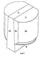
- Figure 1 shows in perspective a bi-lobate container having flat inset portions.
- Figure 2 shows in section a skirted lid suitable for use on the container shown in Figure 1.
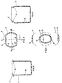
- Figure 3 shows on a smaller scale a transverse section of the body of the container on the line AA of Figure 1.
- Figure 4 shows a longitudinal section of the container on the line BB of Figure 3.
- Figure 5 shows a longitudinal section of the container on the line CC of Figure 3.
- Figure 6 shows diagrammatically a notional arrangement in which the inset portions of Figure 3 are removed and the protruding portions or lobes are moved notionally together.
- Figure 7 shows on a larger scale a core suitable for use in shaping the container shown in Figure 1.
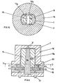
- Figure 8 shows on a smaller scale in section the core of Figure 7 in position in a core-and-cavity mould.
- Figure 9 shows in section the mould of Figure 8 with the second segment of the core withdrawn and the first segments closed together.
- Figure 10 shows a section on the line DD of Figure 8 after the cores have been moved together as shown in Figure 9.
- Figures 11 and 12 show a modification of the mould shown in Figures 8, 9 and 10.
- Figure 13 shows in detail on a larger scale and in section part of a modified container and lid on which a second container is stacked.
- Figure 14 shows in section a further modification of the container of Figure 1.
- Figure 15 shows in perspective a lidded tri-lobate container.
- Figure 16 shows in section a core for shaping the tri-lobate container of Figure 15.
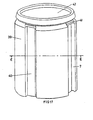
- Figure 17 shows in perspective a lidded fluted container.
- Figure 18 shows a section on the line EE of Figure 17.
- Figure 19 shows in perspective a lidded rectangular container.
- Figure 20 shows in section a core for shaping the container of Figure 19.
- Figure 1 shows an open-
mouth container 1 having a body composed of two longitudinal protruding portions orlobes 3 extending in the direction of the principal axis of the container and twoflat inset portions 4 which are inset relative tolobes 3.Lobes 3 andflat inset portions 4 haveextensions Extensions perimeter 7 of theopen mouth 8. Theextensions 5 oflobes 3 extend inwardly of the body so thatinner surfaces 9 oflobes 3 lie outside (and are therefore undercut by)perimeter 7 ofopen mouth 8 as is shown in Figure 3. This enables a suitably sizedcircular lid 2 as shown in Figure 2 to be applied toperimeter 7 without overhanginglobes 3. - In
contrast extensions 6 are straight extensions offlat inset portions 4 not extending inwards of the body. Accordingly, as is shown in Figure 3,inner surfaces 10 ofinset portions 4 lie withinperimeter 7 ofopen mouth 8. This means that ifinset portions 4 are notionally removed fromcontainer 1 as shown in Figure 6 andlobes 3 are notionally moved inwards until their longitudinal boundaries 11 (see Figure 1) touch, then theirinner surfaces 9 would define a notional surface as shown in Figure 6 which could notionally be passed throughopen mouth 8. The importance of this is that it enablescontainer 1 to be shaped around acore 12 as shown in Figure 7 despite the undercutting oflobes 3 byperimeter 7 for reasons which will now be explained. -
Core 12 hasfirst segments 13 separated by taperedsecond segment 14. During moulding in amould comprising core 12 andcavity 15 as shown in Figures 8, 9 and 10 the internal sur- . faces 9 oflobes 3 andpart 10a of theinternal surface 10 offlat inset portion 4 are defined respectively by outer longitudinal surfaces 13a and 13b offirst segments 13. At the same time, theremainder 10b of theinternal surface 10 offlat inset portion 4 is defined by outerlongitudinal surface 14a ofsecond segment 14.Extension 6 does not extend inwards offlat inset portion 4, with the result thatflat inset portion 4 does not undercutperimeter 7 ofopen mouth 8. Thereforesecond segment 14 ofcore 12 can be withdrawn from newly mouldedcontainer 1 through itsopen mouth 8 whereupon it vacatesspace 16 shown bounded by dashed lines in Figure 9.First components 13 are moved into space 16 (as shown bounded by dashed lines in Figure 10) and then they can be withdrawn together throughperimeter 7 ofopen mouth 8. Hence, despite the undercutting oflobes 3 byperimeter 7,core 12 can be withdrawn fromcontainer 1 with a minimum of three movements ofsegments - tive to
container 1. - The mould shown in Figures 8, 9 and 10 is provided with
bars 17 which guidesecond segment 14 during its withdrawal. Pushrods 18 are provided which are used to movefirst segments 13 intospace 16 vacated bysecond segment 14 whereaftercavity 15 andcontainer 1 can be lifted clear offirst segments 13 during which movementfirst segments 13 are passed throughopen mouth 8. Retractable bars 19 are provided to retractcomponents 20 ofcavity 15 so thatcontainer 1 can be knocked out ofcavity 15 by a blow onsprue 21. - The
lobes 3 andinset portions 4 ofcontainer 1 are tapered at an angle of 0.25° to the principal axis ofcontainer 1 to facilitate withdrawal ofsecond segment 14 and the knocking ofcontainer 1 out ofcavity 15. The taper is exaggerated for clarity in Figures 1, 4, 5, 8, 10, 11 and 12. - Figures 11 and 12 show a modification to the mould shown in Figures 8, 9 and 10. The modification consists of providing inclined guide bars 17a so that withdrawal of
second segment 14 causes a closing together of guide bars 17a which in turn causes a simultaneous movement offirst segments 13 intospace 16. The modification has the advantage of obviating the use ofpush rods 18. - Figure 13 shows
circular lid 2 fitted intoperimeter 7 ofopen mouth 8.Lid 2 has adependent skirt 22 provided with alip 23 which makes a snap- action fit over a co-operatingbarbed profile 24 ofextensions Lid 2 is modified by the provision of an upstandingcircumferential flange 25 andbase 26 of the container is modified by the provision ofdependent studs 27.Flange 25 andstuds 27 co-operate to locate stacked lidded containers one on top of another. - Figure 14 shows a modified
container body 28 which is a modification of the body ofcontainer 1. Like the body ofcontainer 1, the modifiedcontainer body 28 haslobes 31 which are arcs of a common circle. The modification consists of replacingflat inset portions 4 of the body ofcontainer 1 bycurved inset portions 29. The minimum diameter of the modifiedcontainer body 28 throughmidpoints 30 ofinset portions 29 is 96% of the diameter of common circle on whichlobes 31 lie. Theinset portions 29 subtend an angle of 60° to the principal axis with the result that in section transverse to the principal axis,container body 28 has the shape of an oblate circle. The curvature ofinset portions 29 is merged into the curvature oflobes 31 and this disguises the presence ofinset portions 29 and gives the modified container body 28 a cylindrical appearance. - Figure 15 shows a lidded
tri-lobate container 32 having threelobes 33 and threecurved inset portions 34. - Figure 16 shows a core 35 suitable for using in shaping
container 32.Core 35 consists of three first segments 36 separated by a three-armedsecond segment 37. - Figures 17 and 18 show a lidded container 38 having four
lobes 39 and inset portions which arelongitudinal flutes 40.Ledges 41 are provided overflutes 40 so as to provide a fulcrum for use when levering snap-fittinglid 42 off container 38. - Figures 18 and 19 show a rectangular
lidded container 43 having flat protrudingportions 44 andfluted inset portions 45 surmounted byledges 46 each of which provides a fulcrum for use when levering snap-fitting lid 50 offcontainer 43. Figure 20 shows a core 47 suitable for use in shapingcontainer 43.Core 47 consists of fourfirst segments 48 separated bysecond segment 49.
Claims (12)
Applications Claiming Priority (4)
| Application Number | Priority Date | Filing Date | Title |
|---|---|---|---|
| GB3315777 | 1977-08-08 | ||
| GB3315777 | 1977-08-08 | ||
| GB4934577 | 1977-11-28 | ||
| GB4934577 | 1977-11-28 |
Publications (2)
| Publication Number | Publication Date |
|---|---|
| EP0000823A1 EP0000823A1 (en) | 1979-02-21 |
| EP0000823B1 true EP0000823B1 (en) | 1989-01-18 |
Family
ID=26261744
Family Applications (1)
| Application Number | Title | Priority Date | Filing Date |
|---|---|---|---|
| EP19780300221 Expired EP0000823B1 (en) | 1977-08-08 | 1978-08-01 | Open-mouth containers and method and mould core for making them |
Country Status (8)
| Country | Link |
|---|---|
| EP (1) | EP0000823B1 (en) |
| JP (1) | JPS5442328A (en) |
| AU (1) | AU521179B2 (en) |
| BR (1) | BR7805059A (en) |
| CA (1) | CA1101346A (en) |
| DE (1) | DE2862494D1 (en) |
| ES (1) | ES472432A1 (en) |
| NZ (1) | NZ187978A (en) |
Families Citing this family (5)
| Publication number | Priority date | Publication date | Assignee | Title |
|---|---|---|---|---|
| US4735834A (en) * | 1982-08-30 | 1988-04-05 | Phillips Petroleum Company | Plastic molding |
| FR2602711A1 (en) * | 1986-08-13 | 1988-02-19 | Cahors App Elec | Mould which can be dismantled into several parts, for the manufacture of a plastic tank |
| US7207451B2 (en) * | 2002-02-26 | 2007-04-24 | Graham Packaging Company, L.P. | Molded container with beaded neck |
| JP5326059B1 (en) * | 2013-03-29 | 2013-10-30 | 株式会社ハタ | Container, container injection molding method, and container injection mold |
| EP4541724A1 (en) * | 2023-10-20 | 2025-04-23 | Gerresheimer Vaerloese A/S | Container for pharmaceutical, medical, cosmetic, dietetic and food products and method and apparatus for producing such container |
Family Cites Families (4)
| Publication number | Priority date | Publication date | Assignee | Title |
|---|---|---|---|---|
| US3107838A (en) * | 1960-03-16 | 1963-10-22 | Celluplastics Inc | Bottom closure for a plastic container |
| US3133662A (en) * | 1961-12-13 | 1964-05-19 | Chesebrough Ponds | Container |
| GB1152096A (en) * | 1967-02-24 | 1969-05-14 | Sydney Walter Vivian Davies | Container having a Detachable Lid |
| NL154462B (en) * | 1967-09-15 | 1977-09-15 | Mauser Kg | PLASTIC CAN MANUFACTURED IN A BLOWING PROCESS. |
-
1978
- 1978-07-26 NZ NZ18797878A patent/NZ187978A/en unknown
- 1978-07-27 AU AU38425/78A patent/AU521179B2/en not_active Expired
- 1978-08-01 DE DE7878300221T patent/DE2862494D1/en not_active Expired
- 1978-08-01 EP EP19780300221 patent/EP0000823B1/en not_active Expired
- 1978-08-01 CA CA308,512A patent/CA1101346A/en not_active Expired
- 1978-08-07 BR BR7805059A patent/BR7805059A/en unknown
- 1978-08-08 JP JP9588878A patent/JPS5442328A/en active Pending
- 1978-08-08 ES ES472432A patent/ES472432A1/en not_active Expired
Also Published As
| Publication number | Publication date |
|---|---|
| ES472432A1 (en) | 1979-03-16 |
| DE2862494D1 (en) | 1989-02-23 |
| AU3842578A (en) | 1980-01-31 |
| CA1101346A (en) | 1981-05-19 |
| EP0000823A1 (en) | 1979-02-21 |
| BR7805059A (en) | 1979-04-10 |
| NZ187978A (en) | 1982-05-31 |
| JPS5442328A (en) | 1979-04-04 |
| AU521179B2 (en) | 1982-03-18 |
Similar Documents
| Publication | Publication Date | Title |
|---|---|---|
| US4157762A (en) | Open-mouth containers | |
| US4803031A (en) | Method and apparatus for molding a closure cap | |
| US3190530A (en) | Thin wall container with thickened rim structure | |
| US3452896A (en) | Container | |
| EP1471010B1 (en) | Synthetic resin thin-walled bottle container | |
| US4949861A (en) | Rectangular plastic container with panel support | |
| EP0174029A2 (en) | Container closure, components thereof and method for making same | |
| US4117950A (en) | Plastic closure | |
| IE43499L (en) | Plastics barrel. | |
| EP0000823A1 (en) | Open-mouth containers and method and mould core for making them | |
| EP1178933B1 (en) | Thin-walled container and lid, and also a method for making | |
| US3458077A (en) | Composite bottle cap with liner | |
| WO2004014742A2 (en) | Reduced application energy closure | |
| JPH10337769A (en) | Pre-formed body blow-molded into a container and compression molding apparatus for compression-molding the same | |
| CN102159465B (en) | Synthetic resin container | |
| ZA200206837B (en) | Molded closure with flex areas and method. | |
| AU2000275831A1 (en) | Molded closure with flex areas and method | |
| US5992710A (en) | Lid with integrally molded pouring spout | |
| JP3868657B2 (en) | Container with polyester handle | |
| CA1166981A (en) | Containers | |
| US3927795A (en) | Molded article | |
| US6077471A (en) | Mold for forming a container having a continuous neck finish and method for using same | |
| JPH0479293B2 (en) | ||
| JPH0231406Y2 (en) | ||
| JPS6213887B2 (en) |
Legal Events
| Date | Code | Title | Description |
|---|---|---|---|
| PUAI | Public reference made under article 153(3) epc to a published international application that has entered the european phase |
Free format text: ORIGINAL CODE: 0009012 |
|
| AK | Designated contracting states |
Designated state(s): BE CH DE FR GB LU NL SE |
|
| 17P | Request for examination filed | ||
| DET | De: translation of patent claims | ||
| RAP1 | Party data changed (applicant data changed or rights of an application transferred) |
Owner name: IMPERIAL CHEMICAL INDUSTRIES PLC |
|
| NLV1 | Nl: lapsed or annulled due to failure to fulfill the requirements of art. 29p and 29m of the patents act | ||
| GRAA | (expected) grant |
Free format text: ORIGINAL CODE: 0009210 |
|
| AK | Designated contracting states |
Kind code of ref document: B1 Designated state(s): BE CH DE FR GB LU NL SE |
|
| PG25 | Lapsed in a contracting state [announced via postgrant information from national office to epo] |
Ref country code: SE Effective date: 19890118 Ref country code: NL Effective date: 19890118 Ref country code: FR Free format text: THE PATENT HAS BEEN ANNULLED BY A DECISION OF A NATIONAL AUTHORITY Effective date: 19890118 Ref country code: CH Effective date: 19890118 Ref country code: BE Effective date: 19890118 |
|
| REF | Corresponds to: |
Ref document number: 2862494 Country of ref document: DE Date of ref document: 19890223 |
|
| REG | Reference to a national code |
Ref country code: CH Ref legal event code: PL |
|
| EN | Fr: translation not filed | ||
| NLV1 | Nl: lapsed or annulled due to failure to fulfill the requirements of art. 29p and 29m of the patents act | ||
| PG25 | Lapsed in a contracting state [announced via postgrant information from national office to epo] |
Ref country code: LU Free format text: LAPSE BECAUSE OF NON-PAYMENT OF DUE FEES Effective date: 19890831 |
|
| PLBE | No opposition filed within time limit |
Free format text: ORIGINAL CODE: 0009261 |
|
| STAA | Information on the status of an ep patent application or granted ep patent |
Free format text: STATUS: NO OPPOSITION FILED WITHIN TIME LIMIT |
|
| 26N | No opposition filed | ||
| PGFP | Annual fee paid to national office [announced via postgrant information from national office to epo] |
Ref country code: DE Payment date: 19920720 Year of fee payment: 15 |
|
| PGFP | Annual fee paid to national office [announced via postgrant information from national office to epo] |
Ref country code: GB Payment date: 19920803 Year of fee payment: 15 |
|
| PG25 | Lapsed in a contracting state [announced via postgrant information from national office to epo] |
Ref country code: GB Effective date: 19930801 |
|
| GBPC | Gb: european patent ceased through non-payment of renewal fee |
Effective date: 19930801 |
|
| PG25 | Lapsed in a contracting state [announced via postgrant information from national office to epo] |
Ref country code: DE Effective date: 19940503 |
|
| APAH | Appeal reference modified |
Free format text: ORIGINAL CODE: EPIDOSCREFNO |