EP0000806B1 - Fluid pressure circuit protection valves - Google Patents
Fluid pressure circuit protection valves Download PDFInfo
- Publication number
- EP0000806B1 EP0000806B1 EP78300144A EP78300144A EP0000806B1 EP 0000806 B1 EP0000806 B1 EP 0000806B1 EP 78300144 A EP78300144 A EP 78300144A EP 78300144 A EP78300144 A EP 78300144A EP 0000806 B1 EP0000806 B1 EP 0000806B1
- Authority
- EP
- European Patent Office
- Prior art keywords
- valve
- fluid pressure
- closure member
- reservoir
- biassing
- Prior art date
- Legal status (The legal status is an assumption and is not a legal conclusion. Google has not performed a legal analysis and makes no representation as to the accuracy of the status listed.)
- Expired
Links
- 239000012530 fluid Substances 0.000 title claims description 17
- 230000000694 effects Effects 0.000 description 4
- 238000004519 manufacturing process Methods 0.000 description 3
- 238000009825 accumulation Methods 0.000 description 1
- 238000002485 combustion reaction Methods 0.000 description 1
- 230000006835 compression Effects 0.000 description 1
- 238000007906 compression Methods 0.000 description 1
- 238000010276 construction Methods 0.000 description 1
- 230000009977 dual effect Effects 0.000 description 1
- 238000005058 metal casting Methods 0.000 description 1
Images
Classifications
-
- B—PERFORMING OPERATIONS; TRANSPORTING
- B60—VEHICLES IN GENERAL
- B60T—VEHICLE BRAKE CONTROL SYSTEMS OR PARTS THEREOF; BRAKE CONTROL SYSTEMS OR PARTS THEREOF, IN GENERAL; ARRANGEMENT OF BRAKING ELEMENTS ON VEHICLES IN GENERAL; PORTABLE DEVICES FOR PREVENTING UNWANTED MOVEMENT OF VEHICLES; VEHICLE MODIFICATIONS TO FACILITATE COOLING OF BRAKES
- B60T11/00—Transmitting braking action from initiating means to ultimate brake actuator without power assistance or drive or where such assistance or drive is irrelevant
- B60T11/10—Transmitting braking action from initiating means to ultimate brake actuator without power assistance or drive or where such assistance or drive is irrelevant transmitting by fluid means, e.g. hydraulic
- B60T11/28—Valves specially adapted therefor
- B60T11/32—Automatic cut-off valves for defective pipes
- B60T11/326—Automatic cut-off valves for defective pipes in pneumatic systems
Definitions
- This invention relates to fluid pressure circuit protection valves especially but not exclusively for use in fluid pressure reservoir charging systems.
- Fluid pressure reservoir charging arrangements are used extensively in road vehicle braking systems wherein it is convenient to provide charging of a plurality of reservoirs from a single source of fluid pressure, typically a compressor.
- Such braking systems invariably have two service reservoirs for supply fluid pressure to completely independent service air brake circuits and in addition, a secondary or parking brake reservoir is usually provided on heavy vehicles for providing hold-off pressures for holding off spring brakes provided for secondary braking and parking.
- a trailer brake reservoir will also be provided for applying fluid pressure to trailer brakes controlled by signals from the trailer.
- charging circuit protection valves for the purposes of ensuring that if a failure occurs in the pipes or connections of a circuit connected to one reservoir, the remaining good circuits can nevertheless become charged at least to a working pressure.
- a problem exists in such an arrangement because of possible inequality between the strength of the springs employed in such protection valves. In normal production these may vary sufficiently for a protection valve associated with a faulty or leaking reservoir to permit the loss of an air supply to such an extent that the other non-faulty circuits do not become charged.
- the DE-A-2553818 provides in parallel with each protection valve a check valve and a restricted flow path which will always ensure that a supply of air reaches non-faulty reservoir circuits despite a small amount of inequality of the springs of the protection valves. It will be appreciated that an accumulation of some air pressure in a non-faulty reservoir then permits any relevant difference in spring forces to be overcome by the established pressure acting on the relevant area of the protection valve.
- a fluid pressure operable fluid pressure circuit protection valve having an input port and an output port, a valve closure member engageable with a valve seat to close a connection between said ports, biassing means for biassing the closure member against the valve seat, pressure responsive means operable in response to a predetermined pressure at the input port to counteract the biassing means and unseat the closure member, characterised by the closure member having an annular resilient seating portion provided with a transverse cut, the uncounteracted biassing means biassing the closure member being operable in use to deform the transverse cut to substantively close it and increasing fluid pressure at the input port acting to progressively open the transverse cut for fluid flow to the output port prior to lifting of the closure member off the valve seat.
- a reservoir charging arrangement for a multi-circuit brake system which by employing such a protection valve for one or some of a plurality of reservoirs to be charged from a single source, it is ensured that one or some reservoirs are normally assured of becoming charged prior to others.
- the reservoir charging arrangement shown therein comprises a compressor to be driven by the internal combustion engine of the vehicle in which the arrangement is installed as part of the braking system.
- the compressor denoted by reference 1 is controlled by a governor denoted by reference 2 and the output of the compressor is fed to an air dryer 3 of known form, the output of which is connected in common to the supply ports of four single circuit protection valves denoted by references 4, 5, 6 and 7.
- These protection valves precede reservoirs 8, 9, 10 and 11.
- the reservoirs 8 and 9 are service reservoirs, the outputs of which would be connected to respective sides of a driver's dual circuit foot valve.
- the reservoir 10 comprises the secondary or parking air reservoir, the output of which would be to a manually operable spring and parking brake control valve in the cab of the vehicle.
- the reservoir 11 comprises the trailer reservoir source, the output of which would be connected to trailer relay valves for providing supplies to a trailer when connected to the vehicle.
- the protection valves 4 and 5 are valves as shown in Fig. 2. From the cutaway illustration of Fig. 2, the construction of the valve is clearly visible and it will be seen that it comprises a main body denoted by reference 21 having a supply input port 22 in a screw insert 23 providing a valve seat 31 against which a springloaded valve closure member 24 engages through its resilient seat 25. Spring biassing is provided by spring 26, the thrust of which is adjustable by a suitable screw 27 bearing against a pressure plate 28.
- the output port is denoted by reference 29.
- the protection valve In operation of the protection valve, when the air pressure at the supply input port attains a pressure which is sufficient to overcome the spring 26, the member 24 lifts off seat 31 and the supply pressure then acts upon the full area of the stem of 24 embraced by the sliding seal 30, holding the member 24 raised against the effect of the spring. Should a failure in the circuit which is connected to the delivery port occur, the valve closes to support a pressure typically about 0,4. 10 6 Pa (60 p.s.i.) at the input port and any remaining circuits connected to the same source of supply are assured of an air supply not less than this pressure.
- the resilient seat 25 of the protection valve of Fig. 2 is provided as shown in Fig. 4 with a contacting upstanding annular raised portion, having a passage cut across it which for pressures somewhat below the aforesaid 0,4. 10 6 Pa (60 p.s.i.) provides a restricted flow path through the valve.
- the cut in the resilient raised portion of the valve seat becomes progressively closed owing to the effect of the spring 26 causing compression of the resilient raised portion.
- the valve operates to completely seal the connection between the supply port 22 and the output port 29. Since the protection valves 6 and 7 are not provided with such restricted flow paths, it is always ensured that the reservoirs 8 and 9 are charged preferentially when re-, charging of a discharged system is commencing.
- FIG. 3 An alternative form of protection valve is shown in Fig. 3, and this is very similar to the valve of Fig. 2 with the added feature that an additional check valve with a light spring is provided within the central plunger, and now denoted by reference 34.
- the central check valve has a resilient closure member 35 and again the upstanding annular portion of the seat 35 which bears against a hard valve seat 32 provided on the upper surface of a screw member 33, is provided with a transverse cut such that at intermediate pressures as aforesaid, a restricted flow path is provided across the check valve.
- the reason for the added check valve in the valve of Fig. 3 is to inhibit feedback as between one reservoir and another.
- a reservoir such as the service reservoir 8 connected to the supply via a protection valve such as shown in Fig. 2
- the plunger 24 is raised and a loss of pressure in one or other of the other reservoirs can be replenished to a certain extent by reverse flow from the reservoir 8 to the depleted reservoir.
- the valve of Fig. 1 In the case of the valve of Fig.
- valves 4 and 5 of the arrangement of Fig. 1 may be of the type described with reference to Fig. 2, such as to provide the possibility of feedback, it may be desirable to provide valves not permitting feedback for the protection valves 6 and 7.
- the question as to whether one or more of the protection valves 8, 9, 10 or 11 are required to prevent feedback will depend upon the vehicle builder requirements.
- the protection valves 4, 5, 6 and 7 may all be constructed in a single metal casting instead of as single valves.
Landscapes
- Engineering & Computer Science (AREA)
- Transportation (AREA)
- Mechanical Engineering (AREA)
- Valves And Accessory Devices For Braking Systems (AREA)
Description
- This invention relates to fluid pressure circuit protection valves especially but not exclusively for use in fluid pressure reservoir charging systems.
- Fluid pressure reservoir charging arrangements are used extensively in road vehicle braking systems wherein it is convenient to provide charging of a plurality of reservoirs from a single source of fluid pressure, typically a compressor. Such braking systems invariably have two service reservoirs for supply fluid pressure to completely independent service air brake circuits and in addition, a secondary or parking brake reservoir is usually provided on heavy vehicles for providing hold-off pressures for holding off spring brakes provided for secondary braking and parking. In addition, if a trailer is to be attached to the vehicle, a trailer brake reservoir will also be provided for applying fluid pressure to trailer brakes controlled by signals from the trailer.
- In charging circuits for the respective reservoirs in such an arrangement it is usual to include charging circuit protection valves for the purposes of ensuring that if a failure occurs in the pipes or connections of a circuit connected to one reservoir, the remaining good circuits can nevertheless become charged at least to a working pressure. A problem exists in such an arrangement because of possible inequality between the strength of the springs employed in such protection valves. In normal production these may vary sufficiently for a protection valve associated with a faulty or leaking reservoir to permit the loss of an air supply to such an extent that the other non-faulty circuits do not become charged. In order to overcome such a problem, the DE-A-2553818 provides in parallel with each protection valve a check valve and a restricted flow path which will always ensure that a supply of air reaches non-faulty reservoir circuits despite a small amount of inequality of the springs of the protection valves. It will be appreciated that an accumulation of some air pressure in a non-faulty reservoir then permits any relevant difference in spring forces to be overcome by the established pressure acting on the relevant area of the protection valve.
- Even with a system arranged with parallel restrictive passages such as described in the aforementioned DE-A-2553818, there is a problem which is not dealt with or solved by the said document. In such systems, again as a result of inequality of the springs of the protection valves or slightly different effective areas, a spring brake reservoir used for parking and secondary braking may become fully charged before the reservoir or reservoirs supplying the service brakes of the vehicle. As a result, the vehicle may be capable of having its parking brakes released whilst the service brake circuits, not having yet received their charged pressure, may be inoperable. It has also been proposed in DE-A-2,355,456 to provide the valve closure member of a multicircuit protection valve with two concentric annular portions the outer one of which is resilient and shallower than the inner one and the inner one of which is provided with a transverse passage. By virtue of the change of effective area which occurs as the pressure increases to a value at which the outer annular portion is unseated operating tolerances of the springs of multi- circuit protection valves are rendered uncritical. However there can be problems associated with the consistent manufacture of such closure members with annuli of precisely different heights.
- It is an object of the invention to overcome the shortcomings of the prior proposals.
- According to the present invention there is provided a fluid pressure operable fluid pressure circuit protection valve having an input port and an output port, a valve closure member engageable with a valve seat to close a connection between said ports, biassing means for biassing the closure member against the valve seat, pressure responsive means operable in response to a predetermined pressure at the input port to counteract the biassing means and unseat the closure member, characterised by the closure member having an annular resilient seating portion provided with a transverse cut, the uncounteracted biassing means biassing the closure member being operable in use to deform the transverse cut to substantively close it and increasing fluid pressure at the input port acting to progressively open the transverse cut for fluid flow to the output port prior to lifting of the closure member off the valve seat.
- By virtue of the present invention, there can be provided a reservoir charging arrangement for a multi-circuit brake system which by employing such a protection valve for one or some of a plurality of reservoirs to be charged from a single source, it is ensured that one or some reservoirs are normally assured of becoming charged prior to others.
- In order that the invention may be more clearly understood and readily carried into effect, the same will be further described by way of example with reference to the accompanying drawings of which:-
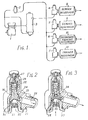
- Fig. 1 illustrates a typical reservoir charging arrangement for a vehicle braking system and
- Fig. 2 illustrates a circuit protection valve (cutaway view) embodying protection valves in accordance with the invention and
- Fig. 3 illustrates an alternative form of protection valve formed in accordance with the invention, and
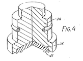
- Fig. 4 shows an enlarged view of the plunger of the protection valve of Fig. 2.
- Referring to Fig. 1, the reservoir charging arrangement shown therein comprises a compressor to be driven by the internal combustion engine of the vehicle in which the arrangement is installed as part of the braking system. The compressor denoted by reference 1 is controlled by a governor denoted by reference 2 and the output of the compressor is fed to an
air dryer 3 of known form, the output of which is connected in common to the supply ports of four single circuit protection valves denoted byreferences reservoirs reservoirs reservoir 10 comprises the secondary or parking air reservoir, the output of which would be to a manually operable spring and parking brake control valve in the cab of the vehicle. Thereservoir 11 comprises the trailer reservoir source, the output of which would be connected to trailer relay valves for providing supplies to a trailer when connected to the vehicle. - The
protection valves reference 21 having asupply input port 22 in a screw insert 23 providing avalve seat 31 against which a springloadedvalve closure member 24 engages through itsresilient seat 25. Spring biassing is provided by spring 26, the thrust of which is adjustable by a suitable screw 27 bearing against apressure plate 28. The output port is denoted byreference 29. - In operation of the protection valve, when the air pressure at the supply input port attains a pressure which is sufficient to overcome the spring 26, the
member 24 lifts offseat 31 and the supply pressure then acts upon the full area of the stem of 24 embraced by the slidingseal 30, holding themember 24 raised against the effect of the spring. Should a failure in the circuit which is connected to the delivery port occur, the valve closes to support a pressure typically about 0,4. 106 Pa (60 p.s.i.) at the input port and any remaining circuits connected to the same source of supply are assured of an air supply not less than this pressure. - In order to ensure that the
service reservoirs resilient seat 25 of the protection valve of Fig. 2 is provided as shown in Fig. 4 with a contacting upstanding annular raised portion, having a passage cut across it which for pressures somewhat below the aforesaid 0,4. 106 Pa (60 p.s.i.) provides a restricted flow path through the valve. - For pressures progressively less than a certain pressure, the cut in the resilient raised portion of the valve seat becomes progressively closed owing to the effect of the spring 26 causing compression of the resilient raised portion. With the spring entirely uncounteracted, the valve operates to completely seal the connection between the
supply port 22 and theoutput port 29. Since theprotection valves 6 and 7 are not provided with such restricted flow paths, it is always ensured that thereservoirs - An alternative form of protection valve is shown in Fig. 3, and this is very similar to the valve of Fig. 2 with the added feature that an additional check valve with a light spring is provided within the central plunger, and now denoted by
reference 34. In this case, the central check valve has aresilient closure member 35 and again the upstanding annular portion of theseat 35 which bears against ahard valve seat 32 provided on the upper surface of ascrew member 33, is provided with a transverse cut such that at intermediate pressures as aforesaid, a restricted flow path is provided across the check valve. - The reason for the added check valve in the valve of Fig. 3 is to inhibit feedback as between one reservoir and another. In this connection, it will be noted that with a reservoir such as the
service reservoir 8 connected to the supply via a protection valve such as shown in Fig. 2, with a fully charged reservoir, theplunger 24 is raised and a loss of pressure in one or other of the other reservoirs can be replenished to a certain extent by reverse flow from thereservoir 8 to the depleted reservoir. In the case of the valve of Fig. 3 however, by virtue of thecentral check valve 35, even though theplunger 34 is raised under the effect of a fully charged reservoir pressure at the delivery port fed via a slot to the underside of theplunger 34, thecheck valve 35 remains closed when a depression of the pressure at the supply port occurs, thereby preventing appreciable feed-back from one reservoir to another. - Typically, whilst the
valves protection valves 6 and 7. In general, the question as to whether one or more of theprotection valves - The
protection valves - From the foregoing it will be appreciated that by virtue of the present invention and whereby the protection valves of a multi-circuit braking system which are provided in the charging paths for reservoirs for the or each service braking circuit, it can be ensured that during recharging of the system, a parking spring brake reservoir does not become recharged before a service reservoir to an extent which can permit release of a parking brake. This is achievable even in cases where the spring of a spring brake protection reservoir is slightly less effective than the spring of a service reservoir due to manufacturing tolerances.
Claims (2)
Applications Claiming Priority (2)
| Application Number | Priority Date | Filing Date | Title |
|---|---|---|---|
| GB3398177 | 1977-08-12 | ||
| GB3398177 | 1977-08-12 |
Publications (2)
| Publication Number | Publication Date |
|---|---|
| EP0000806A1 EP0000806A1 (en) | 1979-02-21 |
| EP0000806B1 true EP0000806B1 (en) | 1982-09-29 |
Family
ID=10359863
Family Applications (1)
| Application Number | Title | Priority Date | Filing Date |
|---|---|---|---|
| EP78300144A Expired EP0000806B1 (en) | 1977-08-12 | 1978-07-12 | Fluid pressure circuit protection valves |
Country Status (5)
| Country | Link |
|---|---|
| EP (1) | EP0000806B1 (en) |
| AT (1) | AT377234B (en) |
| DE (1) | DE2862046D1 (en) |
| IT (1) | IT1160565B (en) |
| ZA (1) | ZA784085B (en) |
Cited By (1)
| Publication number | Priority date | Publication date | Assignee | Title |
|---|---|---|---|---|
| DE4219448A1 (en) * | 1992-06-13 | 1993-12-16 | Wabco Westinghouse Fahrzeug | Protection system for a pressure medium system |
Families Citing this family (1)
| Publication number | Priority date | Publication date | Assignee | Title |
|---|---|---|---|---|
| DE502004009794D1 (en) | 2004-11-15 | 2009-09-03 | Weigert Chem Fab | Method for cleaning dishes |
Family Cites Families (10)
| Publication number | Priority date | Publication date | Assignee | Title |
|---|---|---|---|---|
| DE2138996A1 (en) * | 1971-08-04 | 1973-02-15 | Bosch Gmbh Robert | MULTI-CIRCUIT PROTECTION VALVE |
| DE2143733B2 (en) * | 1971-09-01 | 1975-10-09 | 7000 Stuttgart | Multi-circuit protection valve |
| FR2190652B1 (en) * | 1971-09-01 | 1976-05-07 | Bosch Gmbh Robert | |
| DD101477A1 (en) * | 1972-12-15 | 1973-11-12 | ||
| DE2355456C3 (en) * | 1973-11-06 | 1981-09-10 | Wabco Fahrzeugbremsen Gmbh, 3000 Hannover | Multi-circuit protection valve for compressed air systems for vehicles, in particular compressed air brake systems for road vehicles |
| GB1474373A (en) * | 1974-07-10 | 1977-05-25 | Bendix Westinghouse Ltd | Spring-loaded valves |
| DE2525146B2 (en) * | 1975-06-06 | 1979-02-01 | Graubremse Gmbh, 6900 Heidelberg | Multi-circuit protection valve for braking systems in motor vehicles |
| DE2553818A1 (en) * | 1975-11-29 | 1977-06-02 | Wabco Westinghouse Gmbh | MULTI-CIRCUIT PROTECTION VALVE FOR MULTI-CIRCUIT BRAKE SYSTEMS IN MOTOR VEHICLES |
| DE2558844C3 (en) * | 1975-12-27 | 1979-10-18 | Graubremse Gmbh, 6900 Heidelberg | Method and device for supplying a motor vehicle brake system protected by a multi-circuit protection valve with compressed air |
| DE2639721A1 (en) * | 1976-09-03 | 1978-03-09 | Bosch Gmbh Robert | MULTI-CIRCUIT PROTECTION VALVE FOR COMPRESSED AIR SYSTEMS |
-
1978
- 1978-07-12 EP EP78300144A patent/EP0000806B1/en not_active Expired
- 1978-07-12 DE DE7878300144T patent/DE2862046D1/en not_active Expired
- 1978-07-18 ZA ZA00784085A patent/ZA784085B/en unknown
- 1978-07-31 IT IT68820/78A patent/IT1160565B/en active
- 1978-08-14 AT AT0589578A patent/AT377234B/en not_active IP Right Cessation
Cited By (1)
| Publication number | Priority date | Publication date | Assignee | Title |
|---|---|---|---|---|
| DE4219448A1 (en) * | 1992-06-13 | 1993-12-16 | Wabco Westinghouse Fahrzeug | Protection system for a pressure medium system |
Also Published As
| Publication number | Publication date |
|---|---|
| ATA589578A (en) | 1984-07-15 |
| EP0000806A1 (en) | 1979-02-21 |
| IT1160565B (en) | 1987-03-11 |
| ZA784085B (en) | 1979-07-25 |
| AT377234B (en) | 1985-02-25 |
| IT7868820A0 (en) | 1978-07-31 |
| DE2862046D1 (en) | 1982-11-11 |
Similar Documents
| Publication | Publication Date | Title |
|---|---|---|
| US4080004A (en) | Service and emergency trailer valve | |
| US3947072A (en) | Brake system | |
| EP0203313A1 (en) | Fluid pressure braking system | |
| CN107438544A (en) | Compressed air unit for vehicles with double relay valve | |
| US4191428A (en) | Air brake system with pressure holding valve | |
| US4125294A (en) | Fluid pressure control valve device arranged for fail-safe operation | |
| EP0000806A1 (en) | Fluid pressure circuit protection valves | |
| JPS5924022B2 (en) | brake control valve | |
| EP0234042B1 (en) | Dual circuit brake valve | |
| US3583772A (en) | Dual range variable load valve device | |
| US2254990A (en) | Automatic safety valve for hydraulic brakes | |
| US6776461B2 (en) | Brake pressure regulating device for vehicles | |
| US4119351A (en) | Air brake system with pressure holding valve | |
| US4696521A (en) | Vehicle anti-skid air braking systems | |
| EP0064357A1 (en) | Relay valves with output pressure predominance | |
| US3159433A (en) | Brake proportioning valves | |
| US2876045A (en) | Emergency braking system for automotive vehicles | |
| US4217004A (en) | Controlling means for a dual vehicle hydraulic braking system | |
| FI64773B (en) | PNEUMATIC BROMS MANAGEMENT FOR FORD | |
| JPS5917728Y2 (en) | Fluid pressure brake device | |
| EP0018770B1 (en) | System protection valve | |
| JPS6234573B2 (en) | ||
| JPH0676052B2 (en) | Trip differential pressure dash control valve using the same plunger | |
| US2203042A (en) | Valve mechanism for fluid pressure systems | |
| EP0075391B1 (en) | Vehicle brake pressure proportioning valves |
Legal Events
| Date | Code | Title | Description |
|---|---|---|---|
| PUAI | Public reference made under article 153(3) epc to a published international application that has entered the european phase |
Free format text: ORIGINAL CODE: 0009012 |
|
| AK | Designated contracting states |
Designated state(s): BE CH DE FR GB NL |
|
| 17P | Request for examination filed | ||
| DET | De: translation of patent claims | ||
| GRAA | (expected) grant |
Free format text: ORIGINAL CODE: 0009210 |
|
| AK | Designated contracting states |
Designated state(s): BE CH DE FR GB NL |
|
| REF | Corresponds to: |
Ref document number: 2862046 Country of ref document: DE Date of ref document: 19821111 |
|
| PGFP | Annual fee paid to national office [announced via postgrant information from national office to epo] |
Ref country code: GB Payment date: 19920630 Year of fee payment: 15 |
|
| PGFP | Annual fee paid to national office [announced via postgrant information from national office to epo] |
Ref country code: FR Payment date: 19920707 Year of fee payment: 15 |
|
| PGFP | Annual fee paid to national office [announced via postgrant information from national office to epo] |
Ref country code: CH Payment date: 19920709 Year of fee payment: 15 |
|
| PGFP | Annual fee paid to national office [announced via postgrant information from national office to epo] |
Ref country code: DE Payment date: 19920727 Year of fee payment: 15 |
|
| PGFP | Annual fee paid to national office [announced via postgrant information from national office to epo] |
Ref country code: NL Payment date: 19920731 Year of fee payment: 15 |
|
| PGFP | Annual fee paid to national office [announced via postgrant information from national office to epo] |
Ref country code: BE Payment date: 19920831 Year of fee payment: 15 |
|
| PG25 | Lapsed in a contracting state [announced via postgrant information from national office to epo] |
Ref country code: GB Effective date: 19930712 |
|
| PG25 | Lapsed in a contracting state [announced via postgrant information from national office to epo] |
Ref country code: CH Effective date: 19930731 Ref country code: BE Effective date: 19930731 |
|
| BERE | Be: lapsed |
Owner name: BENDIX LTD Effective date: 19930731 |
|
| PG25 | Lapsed in a contracting state [announced via postgrant information from national office to epo] |
Ref country code: NL Effective date: 19940201 |
|
| GBPC | Gb: european patent ceased through non-payment of renewal fee |
Effective date: 19930712 |
|
| NLV4 | Nl: lapsed or anulled due to non-payment of the annual fee | ||
| PG25 | Lapsed in a contracting state [announced via postgrant information from national office to epo] |
Ref country code: FR Effective date: 19940331 |
|
| REG | Reference to a national code |
Ref country code: CH Ref legal event code: PL |
|
| PG25 | Lapsed in a contracting state [announced via postgrant information from national office to epo] |
Ref country code: DE Effective date: 19940401 |
|
| REG | Reference to a national code |
Ref country code: FR Ref legal event code: ST |
|
| PLBE | No opposition filed within time limit |
Free format text: ORIGINAL CODE: 0009261 |
|
| STAA | Information on the status of an ep patent application or granted ep patent |
Free format text: STATUS: NO OPPOSITION FILED WITHIN TIME LIMIT |