EP0000205B1 - Heat pump apparatus and method for increasing the heat content of a fluid and thereafter transferring the heat content to an ambient atmosphere - Google Patents
Heat pump apparatus and method for increasing the heat content of a fluid and thereafter transferring the heat content to an ambient atmosphere Download PDFInfo
- Publication number
- EP0000205B1 EP0000205B1 EP78100297A EP78100297A EP0000205B1 EP 0000205 B1 EP0000205 B1 EP 0000205B1 EP 78100297 A EP78100297 A EP 78100297A EP 78100297 A EP78100297 A EP 78100297A EP 0000205 B1 EP0000205 B1 EP 0000205B1
- Authority
- EP
- European Patent Office
- Prior art keywords
- passageway
- bodies
- region
- fluid
- heat
- Prior art date
- Legal status (The legal status is an assumption and is not a legal conclusion. Google has not performed a legal analysis and makes no representation as to the accuracy of the status listed.)
- Expired
Links
Images

Classifications
-
- F—MECHANICAL ENGINEERING; LIGHTING; HEATING; WEAPONS; BLASTING
- F01—MACHINES OR ENGINES IN GENERAL; ENGINE PLANTS IN GENERAL; STEAM ENGINES
- F01C—ROTARY-PISTON OR OSCILLATING-PISTON MACHINES OR ENGINES
- F01C1/00—Rotary-piston machines or engines
- F01C1/02—Rotary-piston machines or engines of arcuate-engagement type, i.e. with circular translatory movement of co-operating members, each member having the same number of teeth or tooth-equivalents
- F01C1/063—Rotary-piston machines or engines of arcuate-engagement type, i.e. with circular translatory movement of co-operating members, each member having the same number of teeth or tooth-equivalents with coaxially-mounted members having continuously-changing circumferential spacing between them
-
- F—MECHANICAL ENGINEERING; LIGHTING; HEATING; WEAPONS; BLASTING
- F25—REFRIGERATION OR COOLING; COMBINED HEATING AND REFRIGERATION SYSTEMS; HEAT PUMP SYSTEMS; MANUFACTURE OR STORAGE OF ICE; LIQUEFACTION SOLIDIFICATION OF GASES
- F25B—REFRIGERATION MACHINES, PLANTS OR SYSTEMS; COMBINED HEATING AND REFRIGERATION SYSTEMS; HEAT PUMP SYSTEMS
- F25B29/00—Combined heating and refrigeration systems, e.g. operating alternately or simultaneously
-
- F—MECHANICAL ENGINEERING; LIGHTING; HEATING; WEAPONS; BLASTING
- F25—REFRIGERATION OR COOLING; COMBINED HEATING AND REFRIGERATION SYSTEMS; HEAT PUMP SYSTEMS; MANUFACTURE OR STORAGE OF ICE; LIQUEFACTION SOLIDIFICATION OF GASES
- F25B—REFRIGERATION MACHINES, PLANTS OR SYSTEMS; COMBINED HEATING AND REFRIGERATION SYSTEMS; HEAT PUMP SYSTEMS
- F25B30/00—Heat pumps
-
- F—MECHANICAL ENGINEERING; LIGHTING; HEATING; WEAPONS; BLASTING
- F25—REFRIGERATION OR COOLING; COMBINED HEATING AND REFRIGERATION SYSTEMS; HEAT PUMP SYSTEMS; MANUFACTURE OR STORAGE OF ICE; LIQUEFACTION SOLIDIFICATION OF GASES
- F25B—REFRIGERATION MACHINES, PLANTS OR SYSTEMS; COMBINED HEATING AND REFRIGERATION SYSTEMS; HEAT PUMP SYSTEMS
- F25B9/00—Compression machines, plants or systems, in which the refrigerant is air or other gas of low boiling point
Definitions
- the invention relates to a heat pump apparatus and a method used in combination with the heat pump for increasing the heat content of a fluid and thereafter transferring the heat content to an ambient atmosphere.
- such a heat pump used to heat buildings for example, includes an electrically- driven compressor, a throttle valve, an evaporator located in an ambient atmosphere outside the building, and a condenser within the building which discharges heat as a refrigerant is condensed.
- Such heat systems are therefore relatively complicated in structure, have low coefficients of performance based upon actual thermal conversion, and require liquid refrigerant which is expensive and might be toxic.
- the energy input into the pump system is usually electrical and, hence, does not utilize the heat rejected in the electrical energy production.
- the invention as claimed is intended to remedy the known disadvantages by providing an improved, simplified, unidirectional energy converter heat pump apparatus and a method used in combination with the heat pump apparatus for increasing the heat content of a fluid at one location and thereafter transferring the heat content at an ambient temperature to another location so that the heat pump apparatus moves heat from a reservoir at a colder temperature (for example, the outdoor air or a waste heat stream) to a reservoir at a warmer temperature (for example, t, ' utdoor air or a process heat stream), and use a natural heat source, and operate cheap fluids.
- a colder temperature for example, the outdoor air or a waste heat stream
- a warmer temperature for example, t, ' utdoor air or a process heat stream
- the advantages offered by the invention are mainly that the heat pump apparatus provided can extract heat from compressed fluid leaving the compression region of the passageway, and that it can be used with a heat source such as natural gas, oil or coal, or a motor-driven compressor, and which can operate on cheap fluids such as air in contrast to the more expensive and toxic refrigerants used in conventional prior art heat pumps.
- the heat pump of the invention is of relatively simple construction and has a high coefficient of performance. When used for cooling purposes, the reservoirs are simply reversed with the heat pump taking heat from the cooler indoors and exhausting it to the warmer outdoors as in a conventional air-conditioning system.
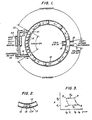
- the apparatus shown includes a closed, continuous loop passageway 10 defined by a housing having walls which are preferably smooth and formed from metal. Disposed within the continuous loop passageway 10 is a plurality of bodies 12, shown in the embodiment of Fig. 1 as solid spheroids. The tolerances or clearances between the surfaces of the bodies 12 and the inside walls of the continuous loop passageway 10 are such as to permit the bodies 12 to move freely along the continuous loop passageway 10. However, fluid flow past the bodies 12 within the continuous loop passageway 10 is substantially prevented.
- the continuous loop passageway 10 has a circular cross section, but with other shaped bodies, other cross sections may be utilized including elliptical or polygonal cross sections.
- the body 12A comprising two bodies 12 welded at 13, has two circumferential lines of contact 15 and 17 with the inside walls of the continuous loop passageway 10. This arrangement does not impede the movement of the body, but increases the sealing effect between the body and the interior wall. At the same time, it decreases the chances of having the bodies 12 pit the interior wall surface of the continuous loop passageway 10 in those embodiments of the invention where a sharp bend occurs in the continuous passageway 10 and, further, reduces clearance problems due to deformations of the spheroids from impacts.
- the continuous loop passageway 10 is divided into sections.
- compressed air from a suitable compressor not shown, enters the continuous loop passageway 10 through conduit 14.
- This causes successive ones of the bodies 12 to be propelled along the continuous loop passageway 10 in a counterclockwise direction as viewed in Fig. 1. That is, the compressed air from conduit 14 along with compressed air from heat exchanger 22, as described below, enters the continuous loop passageway 10 and expands adiabatically imparting kinetic energy in the form of increased forward velocity to each body 12 while the gas between successive ones of the bodies 12 is reduced in temperature.
- the cooler air which has been adiabatically expanded exits to the atmosphere and air from the ambient atmosphere enters the continuous loop passageway 12 through port means 18 and is thereafter compressed in a compression region of the continuous loop passageway 12.
- the ports may be arranged and connected to conventional heat exchanger means (not shown) in any known manner. In an embodiment of the invention, a plurality of ports 16 and 18 is provided.
- the kinetic energy of the moving bodies is used to compress the gas entering at port 18, and the compressed gas exits from the continuous loop passageway 10 through conduit 20 connected to one side of a heat exchanger 22 via check valve 23.
- the temperature of the air is, of course, increased as well as its heat content. Part of the heat is extracted by means of the heat exchanger 22.
- the gas which passes through the heat exchanger 22 is then combined in conduit 14 with the compressed air from an external source (not shown) to propel the bodies 12 in the expander section.
- latch means 21 located at or near the end of the compression region and adapted to prevent backward motion of the bodies in this region after their kinetic energy has been reduced.
- Any conventional latch means may be 'used, such as, for example, a spring-powered, bevelled latch 21 (spring not shown) operating in a manner similar to an ordinary door latch. That is, the latch projects slightly into the continuous loop passageway 10 and is bevelled in the direction of approach of the bodies 12 so that as each body 12 comes into contact with the latch means 21 in a counterclockwise direction it will depress the latch allowing it to pass, but the latch means 21 will not depress to allow the bodies 12 to retreat in a clockwise direction.
- thermodynamic cycle used in the heat pump of the invention is shown in Fig. 3 and is similar to a Brayton cycle. Between successive ones of the bodies 12 there is what can be termed a unit cell. Gas enters the expander section from conduit 14. The unit cell between successive bodies 12 in the expander section then seals off the inlet conduit 14 and adiabatically expands between points 2 and 1 in Fig. 3 to a pressure p, and volume V, at temperature T,. For simplicity, it will be assumed that the pressure p, is atmospheric pressure. The velocity of the lead body 12 is now v j , its maximum value.
- the fresh charge of gas is then compressed between points 4 and 3 in Fig. 3 to volume V 3 at temperature T 3 and pressure p 2 .
- the pressurized heated gas is then exhausted from the compressor section via conduit 20 through check valve 23, and heat is extracted through the heat exchanger means 22.
- the unit cell collapses and the cycle is then repeated, the total work being represented by the area within the lines between points 1, 2, 3 and 4 in Fig. 3.
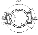
- FIG. 4 The air-conditioning (i.e., cooling) mode of operation of the heat pump is shown in Fig. 4.
- the system is essentially the same as that of Fig. 1 and, accordingly, elements in Fig. 4 which correspond to those of Fig. 1 are identified by like reference numerals.
- port 16 corresponds to the cool air duct of an air-conditioning system; whereas port means 18 corresponds to the warm return.
- heat exchanger means 17 may be connected to ports means 16 and 18, necessitating a slight rearrangement of these ports means 16 and 18 as shown.
- the heat exchanger means 22, in an air-conditioning system will be located external to the building which is being cooled and would correspond to a conventional condensing coil in a refrigeration system.
- the same basic thermodynamic cycle shown in Fig. 3 is employed; however cycles other than the Brayton refrigeration cycle are also possible.
- the expander region takes air from the outdoor heat exchanger means 22 and adiabatically expands it to a temperature lower than the indoor temperature.
- the cooler air is exhausted into the indoors through exit port means 16; or it can be passed through an indoor heat exchanger means.
- the unit cell picks up a charge of warmer indoor air (Q,).
- this warmer air is adiabatically compressed to a higher pressure and temperature; and between points 2 and 3, the heat is exhausted to the outdoors at constant pressure via the heat exchanger means 22 (Q A ) '
- the net work to drive the cycle is provided by make-up air from an air compressor, not shown, passing into the expander section through conduit 14.
- the difference- between the cooling and heating modes is, of course, that in the heating mode, heat is taken from outdoors and pumped indoors; whereas in the cooling mode, heat is taken from the indoors and pumped outdoors.
- Fig. 5 an embodiment of the invention is shown wherein unidirectional energy converters are employed both as the heat pump and as the air compressor designed to supply compressed air to the heat pump.
- the continuous loop passageway of the air compressor loop is indicated generally by the reference numeral 24' and the continuous loop passageway of the heat pump loop by the numeral 26.
- Each of the continuous loop passageways 24 and 26 incorporates two unidirectional energy converter heat pumps in series.
- the air compressor loop 24 operates as follows.
- One portion of atmospheric air (m, + m 2 ) enters the lower leg 26 of the air compressor loop 24 at 28 via conduit 50 and then is compressed as the bodies 30 move upwardly in the lower leg 26.
- Part of the compressed gas exiting from the top of the lower leg 26, m 1 passes through a heat exchanger means 32 where heat is added from an external heat source Q 1 .
- This source may, for example, comprise burning natural gas or any other suitable source of heat.
- the heated, compressed gas is used in an upper leg 34 of the air compressor loop 24 to propel the bodies 30 to the left by adiabatic expansion.
- the gas, m 1 After it has been adiabatically expanded, and reduced in temperature, in upper leg 34, the gas, m 1 , exits at port means 36; while a new charge of atmospheric air (m, + m 2 ) enters at port means 38 where it is compressed by the propelled bodies 30 and exits at 40. Part of the compressed gas, m 1 , is passed through a heat exchanger means 42 where heat is added, as described above, the resulting compressed and heated gas being reintroduced into the lower leg 26 at 44 where it adiabatically expands to propel the bodies 30 to the right. After it has been adiabatically expanded, and reduced in temperature, in the lower leg 26, the gas, m,, exits at 37.
- the two portions (2m,), comprising the adiabatically expanded gas, are then combined in conduit 52, with additional atmospheric air, 2(m 3 -m 1 ), being added in conduit 55 to yield a quantity of gas of 2m 3 .
- One-half of this quantity, or m 3 then enters the input 56 and the remaining half, m 3 , enters input 58, the respective inputs of the two compressor sections of the heat pump loop 26.
- the two individual portions m 2 of the compressed and heated gas which exit from the air compressor loop 24 are passed through conduits 60 and 62, respectively, to the heat exchanger means 48 and 46, respectively, in the continuous loop passageway of the heat pump loop 26.
- these two portions of gas m 2 are individually combined with the two respective compressed gas portions m 3 exiting from the two respective compressor sections at 66 and 64.
- the heat exchangers means 46 and 48 can be of the finned-tube type through which air is blown by means of a fan to heat the air within a building to a temperature much higher than the atmospheric air initially entering the system, the heat emanating from the heat exchangers being indicated by the arrows, Q', in Fig. 5.
- the portion (m 2 + m 3 ) passing through the heat exchanger means 46 is again introduced into the heat pump loop 26 at 68 to propel the bodies 30 by adiabatic expansion and that portion (m 2 + m 3 ) passing through heat exchanger means 48 is fed back into the heat pump loop 26 at 70 to adiabatically expand and propel the bodies 30 forwardly in the lower leg of the heat pump loop 26.
- the two portions of adiabatically expanded gas, 21m 2 + m 3 ), of reduced temperature are then exhausted through conduit 72 to the atmosphere; or can be passed through an additional heat exchanger located within a building when the system is used as an air-conditioning system. In the latter case, the heat exchanger means 46 and 48 will, of course, be located outside the building.
- thermodynamics of the expander and compressor sections of the heat pump of the present invention can be analyzed from ideal considerations as undergoing isentropic processes.
- the processes are not precisely isentropic.
- the processes take place, very nearly, as adiabatic processes, i.e., with no external heat losses, particularly when adequate and properly arranged insulation is attached to the outer walls of the continuous loop passageway 10, 24, 26 forming the expander and compressor sections.
- adiabatic processes i.e., with no external heat losses, particularly when adequate and properly arranged insulation is attached to the outer walls of the continuous loop passageway 10, 24, 26 forming the expander and compressor sections.
- isentropic operation might be assumed for the purpose of analysis, nevertheless the actual operating processes of the heat pump are better described as adiabatic.
- the total external forces acting on the freely movable bodies 12, 30 as they move along the continuous loop passageway 10, 24, 26 must integrate to zero over time in one time period for a particular body to completely transit the loop system under steady-state operation. This is simply in accordance with Newton's second law of motion. Since the movable bodies 12, 30 will encounter friction forces opposing the direction of motion along the continuous loop passageway 10, 24, 26, these friction forces must be counterbalanced by some external force acting in the direction of motion. If the continuous loop passageway 10, 24, 26 along which the bodies 12, 30 travel is in a vertical, or near vertical, plane, such as shown, for example, in the embodiment of Figs. 1 and 5, the force of gravity can be used to provide at least part of the thrust to counterbalance the friction forces.
- loop passageway 10, 24, 26 must be in a horizontal plane, alternative external thruster forces may be applied to the bodies to counterbalance the friction forces.
- mechanically-powered devices such as cams, sprocket wheels, or worm gears, or a linear magnetic motor may be used.
- the number of bodies 12, 30 used in the heat pump apparatus of this invention, the length of the various regions (i.e., expander and compressor) of the continuous loop passageway 10, 24, 26 and the total length of the continuous closed-loop passageways 10, 24, 26 are constants for a particular heat pump design. This means that the control system of the compressor and heat pump loops must regulate the operating parameters to maintain approximately constant distribution of the bodies 12, 30 along the continuous loop passageway 10, 24, 26 for all operating levels.
- the invention has great flexibility in design and performance in that it can be constructed in a continuum of sizes for heating or cooling capability. Furthermore, it can be constructed as a multiple-unit system in which various of the units can be turned ON or OFF as the load requires. This also aids reliability since if one of the units should fail, the system is still operable.
- the system employs conduits, movable bodies, check valves, latches, and heat exchanger means which should contribute greatly to reliability and economy for home heating and cooling systems presently utilized in natural gas or oil heating.
- the invention in an arrangement in which the external compressor is replaced by a "pressurizer" which is an in-line component of the heat pump loop system between the compressor and expander regions.
- a pressurizer which is an in-line component of the heat pump loop system between the compressor and expander regions.
- the apparatus would be designed to take in the same mass flow rate of gas as it exhausts in the vent-intake region, but consequently would compress to a lower pressure than required at the expander inlet.
- the role of the pressurizer then, is to pressure the gas sufficiently to make up this difference using any known method for pressurizing.
- the energy input to the pressurizer is the energy source for running the heat pump, as will be understood.
- the overall length of the heat pump loop shown 26 in Fig. 5, for example, will be about thirty-four times the ' diameter of the bodies 30; while the overall length of the air compressor loop 24 will be about twenty-seven times the diameter of the bodies 30.
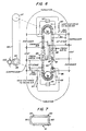
- a further embodiment of the invention is shown wherein serially-arranged unidirectional energy converters form a heat pump.
- the heat pump uses a high pressure stage to convert heat energy into net mechanical energy which is then converted in a low pressure stage of the heat pump to heat energy.
- the unidirectional energy converter heat pumps according to the embodiment shown in Fig. 6 is comprised of two heat engines and two heat pumps operating in parallel.
- a "racetrack" shaped tubular passageway extends within a vertical plane to form a continuous loop passageway 80 containing a plurality of bodies 81.
- the bodies 81 may be spheroids or other desired configuration but preferably the bodies 81 take the form as shown in Fig. 7, of hollowed members having a cylindrical configuration with spherical end surfaces.
- the leading end surface 82 in regard to the direction of travel by a body 81, is convex; whereas the trailing end 83 of the body 81 is concave.
- Ring members 84 are located in recesses formed within the outer cylindrical surface of the body 81 adjacent the convex end surface 82 and the concave end surface 83.
- the hollow bodies 81 provide the necessary design mass and permit greater flexibility to the selection of material for the construction of the bodies 81 independent of the mass required for operation.
- the ring members 84 which are lightly loaded, reduce losses to a minimum due to leakage of the fluid medium around the bodies 81. Also, the use of ring members places less stringent manufacturing tolerances for the production of the bodies 81.
- the bodies 81 move within the continuous loop passageway 80 and operate under light loads, particularly as compared to the loads imposed on the pistons of an internal combustion engine.
- the maximum velocity of the bodies 81 is typically the same as the velocity of pistons in an internal combustion engine.
- a thin film of oil such as, for example, SAE 20 or molybdenum disulfide dry powder, may be used, if desired, for lubrication between the bodies 81 and the racetrack since the fluid temperature does not exceed 816°C and usually does not exceed 649 ° C.
- the continuous loop passageway 80 is divided into regions.
- hot compressed air enters the continuous loop passageway 80 through an entry port coupled to a conduit 85 whereby each body 81 is propelled, in succession, upwardly through the lower right quadrant of the continuous loop passageway 80.
- a second body 81 passes the entry port for conduit 85, a portion of the hot air is closed off from the source, thus forming a unit cell of hot compressed air.
- the hot compressed air in the unit cell is expanded adiabatically until the leading body 81 passes a point in the continuous loop passageway 80 containing an entry port coupled with conduit line 86.
- the exhaust manifold 87 coextends with the vent region wherein cold air is purged from each unit cell between the bodies 81 in the continuous loop passageway 80 and replaced by fresh air fed through an entry port by a manifold 88 from the outside.
- the manifolds 87 and 88 in the vent section terminate at the beginning portion of a compression region where the fresh air in the unit cell between bodies 81 is compressed adiabatically by the kinetic energy of the bodies 81.
- the compression region has two stages in series. The largest portion and first of the compression stages extends to a discharge port for a conduit 89. The largest portion of the air that is compressed between the bodies 81 is passed from the unit cell through conduit 89 into heat exchanger 90 where the compresed air is cooled by heat exchange with room air. From the heat exchanger, the cooled compressed air is reintroduced by conduit 89 into the continuous loop passageway 80 through a port in the second expander region where the air is further cooled adiabatically in a unit cell and exhausted to the atmosphere below atmospheric temperature.
- the second stage thereof utilizes the remaining kinetic energy of the bodies 81 to further compress a small quantity of air remaining in the unit cell.
- the second stage of the compressor region terminates at a port for a conduit 91 to deliver the compressed air from the second stage into a combustion chamber 92 where the compressed air is heated and then fed by conduit 91 to reenter the continuous loop passageway 80 through a port at the entrance of the second expander region.
- Unit cells of air are formed between the bodies 81 after the bodies 81 are passed through a thruster section wherein their direction of travel is altered, and thereafter the bodies 81 pass downwardly along the continuous loop passageway 80.
- the downward path of travel by the bodies 81 is accompanied by the formation of unit cells therebetween while the bodies 81 pass along a second expander region, second vent region and second compression region that are essentially duplicates as far as function is concerned to the corresponding regions already described.
- the unit cells formed between the bodies 81 during their downward travel along the continuous loop passageway 80 are supplied with heated compressed air from conduit 91 and supplied with further quantities of compressed air from conduit 89.
- the leading body 81 of a unit cell passes from the expander section and enters the vent section the hot compressed air is expanded adiabatically whereupon the heat energy of the air is conveted to kinetic energy of the bodies 81.
- the lower, successively-arranged vent region includes a manifold 93 wherein cold air is purged from the unit cell between bodies 81 while the space between the bodies is replenished with fresh air from outside.
- manifolds 87 and 93 communicate with a common duct to exhaust the cold air to the atmosphere.
- the temperature of the exhaust cold air is below atmospheric temperature.
- the second compression region consisting of two stages, the first of which terminates at an exit port for conduit 86 coupled to a heat exchanger 94 to exchange heat with room air.
- the second stage of the compression region extends between the exit port for conduit 86 and an exit port for conduit 85.
- the remaining kinetic energy of the bodies 81 is utilized to further compress a small quantity of air remaining in the unit cell.
- the remaining air in the unit cell is fed by conduit 85 to a combustion chamber 95.
- Combustion chamber 95 functions in the same manner as combustion chamber 92 by reheating the heated compressed air for delivery by conduit 85 into the lower portion of the expander region to form a unit cell between bodies 81 for their upward travel along continuous loop passageway 80.
- the cycle is repeated with the bodies 81 traveling upwardly against the force of gravity along the vent and compressor regions at one side of the vertically-arranged continuous loop passageway 80.
- a parallelly- arranged heat engine and heat pump is formed by the expander, vent and compressor regions at the opposite vertical side of the continuous loop passageway 80 where the body 81 travels downwardly under the force of gravity.
- Thruster regions which take the form of U-shaped continuous loop passageway 80 sections feed the bodies 81 at the discharge side of the compression regions through the use of sprocket wheels or the like into the entry side of the expander regions.
- the thruster regions function to provide a net external force to the bodies 81 in their direction of motion around the passageway to equalize the forces due to friction which act to oppose the body motion.
- the unidirectional continuous passageway loop 80 described is a compound heat engine and a heat pump, thermodynamically a double Brayton cycle.
- the high-pressure stages i.e., the expander regions, convert heat energy into a net mechanical energy that drives the reverse Brayton cycle of a low-pressure stage, i.e., the compressor regions, as a heat pump.
- the compound heat engine and heat pump of this embodiment offers a system wherein the working fluid conveniently takes the form of air throughout the system, thus providing economy, simplicity and environmental cleanliness.
- the straight vertical portions of the passageway conduct the bodies 81 while traveling at their highest velocity, thus minimizing the forces and frictional losses that would otherwise adversely affect travel of the bodies 81.
- the porting of air or other fluid medium used in the system is performed preferably by the bodies 81, thus reducing the number and complexity of in-line valves for the conduit.
- the thruster regions in the schematic illustration include means for conducting the body 81 along the U-shaped configuration of the continuous passageway loop 80 at the ends of the vertical portions thereof. While the U-shaped configuration to the continuous passageway loop 80 can be readily designed to utilize gravity to guide the bodies 81 along their reverse direction of travel, it is nevertheless preferred to provide means such as a sprocket wheel, a linear electromagnetic drive or a linear latch system to insure movement of the bodies 81 throughout the thruster regions.
- a sprocket wheel 96 is shown at both thruster regions to conduct the bodies 81 therealong: Each thruster wheel is coupled by a drive shaft to a pulley 97. The pulleys are interconnected by a timing belt 98.
- One of the pulleys 97 includes a second pulley section 99 coupled by a belt to a pulley on the output shaft of a suitable motor 100.
- This form of drive system provides synchronization between both sprocket wheels 96.
- the motor 100 is preferably a constant speed motor which may be coupled, as an alternative to a belt drive system, by a drive shaft through bevel gears on arbors for the sprocket wheel.
- the heat exchangers 90 and 94 are typically counterflow air-to-air exchangers. Heat exchangers of known construction are capable of accommodating at the high temperature side at maximum temperatures of several hundred degrees C.
- the combustion chambers 92 and 95 may typically take the form of a chamber for the direct combustion of compressed natural gas with the working compressed air or, alternatively, a conventional gas-fired furnace may be utilized. Other conventional external heat sources may also be employed. However, when a direct combustion chamber is utilized, the heat of combustion is completely utilized by the heat pump and gases will be exhausted at subatmospheric temperatures. While, as described hereinbefore, the bodies form necessary valving at ports for the conduits, it may nevertheless be desirable to incorporate check valves at compressor outlets to minimize a backflow of air in part of the cycle. High frequency of response and low pressure drop characteristics are important criteria for selecting such check valves. Reed valves are suitable to form such check valves.
- a back latch mechanism for the bodies may be conveniently used for start-up and shutdown operations of the heat engine and heat pump. At shutdown, it is necessary that the bodies come to rest and remain at predetermined positions so that they will be in the proper position for smooth start-up. This can be achieved by magnetically-operated latches which are actuated at shutdown and retract at start-up. Moveover, at start-up, an air compressor or accumulator may be utilized for the start-up operation.
- a vertically-arranged continuous loop passageway 80 has been shown in Fig. 6 and described above solely for convenience of description. Other variations in the arrangement of the continuous loop passageway 80, including horizontal arrangement, are possible.
Landscapes
- Engineering & Computer Science (AREA)
- Mechanical Engineering (AREA)
- General Engineering & Computer Science (AREA)
- Physics & Mathematics (AREA)
- Thermal Sciences (AREA)
- Compressors, Vaccum Pumps And Other Relevant Systems (AREA)
- Sorption Type Refrigeration Machines (AREA)
Description
- The invention relates to a heat pump apparatus and a method used in combination with the heat pump for increasing the heat content of a fluid and thereafter transferring the heat content to an ambient atmosphere.
- As is known, such a heat pump used to heat buildings, for example, includes an electrically- driven compressor, a throttle valve, an evaporator located in an ambient atmosphere outside the building, and a condenser within the building which discharges heat as a refrigerant is condensed. Such heat systems are therefore relatively complicated in structure, have low coefficients of performance based upon actual thermal conversion, and require liquid refrigerant which is expensive and might be toxic. Furthermore, the energy input into the pump system is usually electrical and, hence, does not utilize the heat rejected in the electrical energy production.
- The attempts so far made to overcome these drawbacks have not yet been very successful, with the exception of the teaching given in the U.S. Patent 3,859,789 concerning a method and an apparatus for converting one form of energy into another with the use of a closed, continuous loop passageway containing a plurality of freely movable, mechanically unrestrained bodies which travel along the passageway in one direction only. The patent, however, does not teach, or in any way suggest, the use of heat exchanger means connected to the passageway at the end of the compression region to extract heat from the compressed fluid leaving the compression region. The heat exchanger means disclosed is used to supply heat to the gas exit from the passageway. There is no recognition that the device described in the patent could be modified so as to serve as a heat pump.
- Based on certain principles as set forth in the cited patent, the invention as claimed is intended to remedy the known disadvantages by providing an improved, simplified, unidirectional energy converter heat pump apparatus and a method used in combination with the heat pump apparatus for increasing the heat content of a fluid at one location and thereafter transferring the heat content at an ambient temperature to another location so that the heat pump apparatus moves heat from a reservoir at a colder temperature (for example, the outdoor air or a waste heat stream) to a reservoir at a warmer temperature (for example, t, 'utdoor air or a process heat stream), and use a natural heat source, and operate cheap fluids.
- This problem in accordance with the present invention is solved by the characterising clauses of the main claims.
- The advantages offered by the invention are mainly that the heat pump apparatus provided can extract heat from compressed fluid leaving the compression region of the passageway, and that it can be used with a heat source such as natural gas, oil or coal, or a motor-driven compressor, and which can operate on cheap fluids such as air in contrast to the more expensive and toxic refrigerants used in conventional prior art heat pumps. At the same time, the heat pump of the invention is of relatively simple construction and has a high coefficient of performance. When used for cooling purposes, the reservoirs are simply reversed with the heat pump taking heat from the cooler indoors and exhausting it to the warmer outdoors as in a conventional air-conditioning system.
- One way of carrying out the invention is described in detail below with reference to the drawings which illustrate only one specific embodiment, in which:
- Fig. 1 is a schematic diagram of the unidirectional energy converter heat pump apparatus of the invention;
- Fig. 2 is an illustration of an alternative form of unrestrained bodies which can be used in the heat pump apparatus of the invention;
- Fig. 3 is a P-V diagram showing the thermodynamic cycle of the heat pump apparatus of Fig. 1;
- Fig. 4 is a schematic diagram of the unidirectional energy converter heat pump apparatus of the invention shown in a cooling (i.e., air conditioning) mode;
- Fig. 5 is an illustration of an embodiment of the invention employing two double unidirectional energy converters, one of which is used as an air compressor and the other of which is used as a heat pump;
- Fig. 6 is a schematic diagram of a unidirectional energy converter forming a heat pump according to a further embodiment of the present invention; and
- Fig. 7 is an illustration of a further form of an unrestrained body which is particularly useful in the embodiment of the invention shown in Fig. 6.
- With reference to the drawings, and particularly to Fig. 1, the apparatus shown includes a closed,
continuous loop passageway 10 defined by a housing having walls which are preferably smooth and formed from metal. Disposed within thecontinuous loop passageway 10 is a plurality ofbodies 12, shown in the embodiment of Fig. 1 as solid spheroids. The tolerances or clearances between the surfaces of thebodies 12 and the inside walls of thecontinuous loop passageway 10 are such as to permit thebodies 12 to move freely along thecontinuous loop passageway 10. However, fluid flow past thebodies 12 within thecontinuous loop passageway 10 is substantially prevented. In the embodiment shown in Fig. 1, for example, thecontinuous loop passageway 10 has a circular cross section, but with other shaped bodies, other cross sections may be utilized including elliptical or polygonal cross sections. In some cases, it is advantageous to weld twobodies 12 together as shown in Fig. 2. Thebody 12A, comprising twobodies 12 welded at 13, has two circumferential lines ofcontact 15 and 17 with the inside walls of thecontinuous loop passageway 10. This arrangement does not impede the movement of the body, but increases the sealing effect between the body and the interior wall. At the same time, it decreases the chances of having thebodies 12 pit the interior wall surface of thecontinuous loop passageway 10 in those embodiments of the invention where a sharp bend occurs in thecontinuous passageway 10 and, further, reduces clearance problems due to deformations of the spheroids from impacts. - As shown in Fig. 1, the
continuous loop passageway 10 is divided into sections. In an expander section, compressed air from a suitable compressor, not shown, enters thecontinuous loop passageway 10 throughconduit 14. This causes successive ones of thebodies 12 to be propelled along thecontinuous loop passageway 10 in a counterclockwise direction as viewed in Fig. 1. That is, the compressed air fromconduit 14 along with compressed air fromheat exchanger 22, as described below, enters thecontinuous loop passageway 10 and expands adiabatically imparting kinetic energy in the form of increased forward velocity to eachbody 12 while the gas between successive ones of thebodies 12 is reduced in temperature. As thebodies 12 pass port means 16 connected to thecontinuous loop passageway 10, the cooler air which has been adiabatically expanded exits to the atmosphere and air from the ambient atmosphere enters thecontinuous loop passageway 12 through port means 18 and is thereafter compressed in a compression region of thecontinuous loop passageway 12. If a liquefiable vapor, rather than air, is used, or if for any other reason it is desired to maintain a closed system, the ports may be arranged and connected to conventional heat exchanger means (not shown) in any known manner. In an embodiment of the invention, a plurality ofports port 18, and the compressed gas exits from thecontinuous loop passageway 10 throughconduit 20 connected to one side of aheat exchanger 22 viacheck valve 23. In the compression process, the temperature of the air is, of course, increased as well as its heat content. Part of the heat is extracted by means of theheat exchanger 22. The gas which passes through theheat exchanger 22 is then combined inconduit 14 with the compressed air from an external source (not shown) to propel thebodies 12 in the expander section. - Another preferred feature of the invention comprises latch means 21 located at or near the end of the compression region and adapted to prevent backward motion of the bodies in this region after their kinetic energy has been reduced. Any conventional latch means may be 'used, such as, for example, a spring-powered, bevelled latch 21 (spring not shown) operating in a manner similar to an ordinary door latch. That is, the latch projects slightly into the
continuous loop passageway 10 and is bevelled in the direction of approach of thebodies 12 so that as eachbody 12 comes into contact with the latch means 21 in a counterclockwise direction it will depress the latch allowing it to pass, but the latch means 21 will not depress to allow thebodies 12 to retreat in a clockwise direction. - One possible thermodynamic cycle used in the heat pump of the invention is shown in Fig. 3 and is similar to a Brayton cycle. Between successive ones of the
bodies 12 there is what can be termed a unit cell. Gas enters the expander section fromconduit 14. The unit cell betweensuccessive bodies 12 in the expander section then seals off theinlet conduit 14 and adiabatically expands betweenpoints 2 and 1 in Fig. 3 to a pressure p, and volume V, at temperature T,. For simplicity, it will be assumed that the pressure p, is atmospheric pressure. The velocity of thelead body 12 is now vj, its maximum value. - The residual gas, whose temperature has been reduced to T, in the adiabatic expansion, is then purged through port means 16 and ambient air at a higher temperature enters through port means 18 and occupies the unit volume between
successive bodies 12. Thus, heat is absorbed in this process from the cold reservoir (e.g., outdoor air). The actual volume between thebodies 12 remains essentially constant during this operation, but the specific volume increases to V4 between points 1 and 4 in Fig. 3. In other words, less mass of gas enters the loop through port means 18 in each unit cell than was exhausted from the unit cells via port means 16. This difference in mass is made up by the additional air which enters the system from the external compressor viaconduit 14. - The fresh charge of gas is then compressed between
points 4 and 3 in Fig. 3 to volume V3 at temperature T3 and pressure p2. The pressurized heated gas is then exhausted from the compressor section viaconduit 20 throughcheck valve 23, and heat is extracted through the heat exchanger means 22. The unit cell collapses and the cycle is then repeated, the total work being represented by the area within the lines betweenpoints - The air-conditioning (i.e., cooling) mode of operation of the heat pump is shown in Fig. 4. The system is essentially the same as that of Fig. 1 and, accordingly, elements in Fig. 4 which correspond to those of Fig. 1 are identified by like reference numerals. In this case,
port 16 corresponds to the cool air duct of an air-conditioning system; whereas port means 18 corresponds to the warm return. As an optional feature, heat exchanger means 17 may be connected to ports means 16 and 18, necessitating a slight rearrangement of these ports means 16 and 18 as shown. The heat exchanger means 22, in an air-conditioning system, will be located external to the building which is being cooled and would correspond to a conventional condensing coil in a refrigeration system. The same basic thermodynamic cycle shown in Fig. 3 is employed; however cycles other than the Brayton refrigeration cycle are also possible. - In the air-conditioning mode between
points 2 and 1 in Fig. 3, the expander region takes air from the outdoor heat exchanger means 22 and adiabatically expands it to a temperature lower than the indoor temperature. The cooler air is exhausted into the indoors through exit port means 16; or it can be passed through an indoor heat exchanger means. Between points 1 and 4 of Fig. 3, the unit cell picks up a charge of warmer indoor air (Q,). Betweenpoints 4 and 3, this warmer air is adiabatically compressed to a higher pressure and temperature; and betweenpoints conduit 14. The difference- between the cooling and heating modes is, of course, that in the heating mode, heat is taken from outdoors and pumped indoors; whereas in the cooling mode, heat is taken from the indoors and pumped outdoors. - In Fig. 5, an embodiment of the invention is shown wherein unidirectional energy converters are employed both as the heat pump and as the air compressor designed to supply compressed air to the heat pump. In Fig. 5, the continuous loop passageway of the air compressor loop is indicated generally by the reference numeral 24' and the continuous loop passageway of the heat pump loop by the numeral 26. Each of the
continuous loop passageways - The
air compressor loop 24 operates as follows. One portion of atmospheric air (m, + m2) enters thelower leg 26 of theair compressor loop 24 at 28 viaconduit 50 and then is compressed as thebodies 30 move upwardly in thelower leg 26. Part of the compressed gas exiting from the top of thelower leg 26, m1, passes through a heat exchanger means 32 where heat is added from an external heat source Q1. This source may, for example, comprise burning natural gas or any other suitable source of heat. The heated, compressed gas is used in anupper leg 34 of theair compressor loop 24 to propel thebodies 30 to the left by adiabatic expansion. After it has been adiabatically expanded, and reduced in temperature, inupper leg 34, the gas, m1, exits at port means 36; while a new charge of atmospheric air (m, + m2) enters at port means 38 where it is compressed by the propelledbodies 30 and exits at 40. Part of the compressed gas, m1, is passed through a heat exchanger means 42 where heat is added, as described above, the resulting compressed and heated gas being reintroduced into thelower leg 26 at 44 where it adiabatically expands to propel thebodies 30 to the right. After it has been adiabatically expanded, and reduced in temperature, in thelower leg 26, the gas, m,, exits at 37. The two portions (2m,), comprising the adiabatically expanded gas, are then combined inconduit 52, with additional atmospheric air, 2(m3-m1), being added inconduit 55 to yield a quantity of gas of 2m3. One-half of this quantity, or m3, then enters the input 56 and the remaining half, m3, entersinput 58, the respective inputs of the two compressor sections of theheat pump loop 26. - It will be noted that the two individual portions m2 of the compressed and heated gas which exit from the
air compressor loop 24 are passed throughconduits heat pump loop 26. In theheat pump loop 26 these two portions of gas m2 are individually combined with the two respective compressed gas portions m3 exiting from the two respective compressor sections at 66 and 64. The heat exchangers means 46 and 48 can be of the finned-tube type through which air is blown by means of a fan to heat the air within a building to a temperature much higher than the atmospheric air initially entering the system, the heat emanating from the heat exchangers being indicated by the arrows, Q', in Fig. 5. The portion (m2 + m3) passing through the heat exchanger means 46 is again introduced into theheat pump loop 26 at 68 to propel thebodies 30 by adiabatic expansion and that portion (m2 + m3) passing through heat exchanger means 48 is fed back into theheat pump loop 26 at 70 to adiabatically expand and propel thebodies 30 forwardly in the lower leg of theheat pump loop 26. The two portions of adiabatically expanded gas, 21m2 + m3), of reduced temperature are then exhausted throughconduit 72 to the atmosphere; or can be passed through an additional heat exchanger located within a building when the system is used as an air-conditioning system. In the latter case, the heat exchanger means 46 and 48 will, of course, be located outside the building. - As the fluid is compressed by the bodies in the compressor sections, most of the kinetic energy of each
body 30 is transferred to increase the enthalpy of the gas and to remove the gas from the compressor section under increased pressure. Similarly, as the fluid in the expander sections of the heat pump loop is adiabatically expanded betweensuccessive bodies 30 in the expander sections, the enthalpy of gas is decreased and energy is transferred to increase the kinetic energy of the bodies. The energy transferred in the various processes along the loop, of course, must be conserved so that at any time the total energy of a particular loop system is constant and the energy input and output is equal in steady-state operation. - The thermodynamics of the expander and compressor sections of the heat pump of the present invention can be analyzed from ideal considerations as undergoing isentropic processes. However, in actual operation, because of internal losses to the working fluid, the processes are not precisely isentropic. The processes take place, very nearly, as adiabatic processes, i.e., with no external heat losses, particularly when adequate and properly arranged insulation is attached to the outer walls of the
continuous loop passageway - In a similar fashion, the total external forces acting on the freely
movable bodies continuous loop passageway movable bodies continuous loop passageway continuous loop passageway bodies loop passageway - The number of
bodies continuous loop passageway loop passageways bodies continuous loop passageway - As will be appreciated, the invention has great flexibility in design and performance in that it can be constructed in a continuum of sizes for heating or cooling capability. Furthermore, it can be constructed as a multiple-unit system in which various of the units can be turned ON or OFF as the load requires. This also aids reliability since if one of the units should fail, the system is still operable.
- The system employs conduits, movable bodies, check valves, latches, and heat exchanger means which should contribute greatly to reliability and economy for home heating and cooling systems presently utilized in natural gas or oil heating.
- It is also possible to use the invention in an arrangement in which the external compressor is replaced by a "pressurizer" which is an in-line component of the heat pump loop system between the compressor and expander regions. In this mode of operation, the apparatus would be designed to take in the same mass flow rate of gas as it exhausts in the vent-intake region, but consequently would compress to a lower pressure than required at the expander inlet. The role of the pressurizer, then, is to pressure the gas sufficiently to make up this difference using any known method for pressurizing. The energy input to the pressurizer is the energy source for running the heat pump, as will be understood.
- In a typical installation, the overall length of the heat pump loop shown 26 in Fig. 5, for example, will be about thirty-four times the 'diameter of the
bodies 30; while the overall length of theair compressor loop 24 will be about twenty-seven times the diameter of thebodies 30. - In Fig. 6, a further embodiment of the invention is shown wherein serially-arranged unidirectional energy converters form a heat pump. The heat pump uses a high pressure stage to convert heat energy into net mechanical energy which is then converted in a low pressure stage of the heat pump to heat energy. More specifically, the unidirectional energy converter heat pumps according to the embodiment shown in Fig. 6 is comprised of two heat engines and two heat pumps operating in parallel. A "racetrack" shaped tubular passageway extends within a vertical plane to form a
continuous loop passageway 80 containing a plurality ofbodies 81. Thebodies 81 may be spheroids or other desired configuration but preferably thebodies 81 take the form as shown in Fig. 7, of hollowed members having a cylindrical configuration with spherical end surfaces. Theleading end surface 82, in regard to the direction of travel by abody 81, is convex; whereas the trailingend 83 of thebody 81 is concave.Ring members 84 are located in recesses formed within the outer cylindrical surface of thebody 81 adjacent theconvex end surface 82 and theconcave end surface 83. Thehollow bodies 81 provide the necessary design mass and permit greater flexibility to the selection of material for the construction of thebodies 81 independent of the mass required for operation. Thering members 84, which are lightly loaded, reduce losses to a minimum due to leakage of the fluid medium around thebodies 81. Also, the use of ring members places less stringent manufacturing tolerances for the production of thebodies 81. Thebodies 81 move within thecontinuous loop passageway 80 and operate under light loads, particularly as compared to the loads imposed on the pistons of an internal combustion engine. The maximum velocity of thebodies 81 is typically the same as the velocity of pistons in an internal combustion engine. A thin film of oil such as, for example,SAE 20 or molybdenum disulfide dry powder, may be used, if desired, for lubrication between thebodies 81 and the racetrack since the fluid temperature does not exceed 816°C and usually does not exceed 649 ° C. - As is shown in Fig. 6, the
continuous loop passageway 80 is divided into regions. In an expander region, hot compressed air enters thecontinuous loop passageway 80 through an entry port coupled to aconduit 85 whereby eachbody 81 is propelled, in succession, upwardly through the lower right quadrant of thecontinuous loop passageway 80. When asecond body 81 passes the entry port forconduit 85, a portion of the hot air is closed off from the source, thus forming a unit cell of hot compressed air. The hot compressed air in the unit cell is expanded adiabatically until the leadingbody 81 passes a point in thecontinuous loop passageway 80 containing an entry port coupled withconduit line 86. As the leadingbody 81 passes this entry port, more compressed air at a lower entry temperature and pressure is fed into the unit cell between thebody 81 fromconduit line 86. The combined compressed air of the unit cell is further expanded adiabatically until the leadingbody 81 passes an exit port communicating with anexhaust manifold 87 in a vent region. The region of the racetrack between the entrance port forconduit 85 and the exit port for theexhaust manifold 87 forms an expander region of thecontinuous loop passageway 80 wherein energy of the hot compressed air fromconduits bodies 81. Theexhaust manifold 87 coextends with the vent region wherein cold air is purged from each unit cell between thebodies 81 in thecontinuous loop passageway 80 and replaced by fresh air fed through an entry port by a manifold 88 from the outside. Themanifolds bodies 81 is compressed adiabatically by the kinetic energy of thebodies 81. - The compression region has two stages in series. The largest portion and first of the compression stages extends to a discharge port for a
conduit 89. The largest portion of the air that is compressed between thebodies 81 is passed from the unit cell throughconduit 89 intoheat exchanger 90 where the compresed air is cooled by heat exchange with room air. From the heat exchanger, the cooled compressed air is reintroduced byconduit 89 into thecontinuous loop passageway 80 through a port in the second expander region where the air is further cooled adiabatically in a unit cell and exhausted to the atmosphere below atmospheric temperature. - Returning to the compressor region, the second stage thereof utilizes the remaining kinetic energy of the
bodies 81 to further compress a small quantity of air remaining in the unit cell. The second stage of the compressor region terminates at a port for aconduit 91 to deliver the compressed air from the second stage into acombustion chamber 92 where the compressed air is heated and then fed byconduit 91 to reenter thecontinuous loop passageway 80 through a port at the entrance of the second expander region. Unit cells of air are formed between thebodies 81 after thebodies 81 are passed through a thruster section wherein their direction of travel is altered, and thereafter thebodies 81 pass downwardly along thecontinuous loop passageway 80. The downward path of travel by thebodies 81 is accompanied by the formation of unit cells therebetween while thebodies 81 pass along a second expander region, second vent region and second compression region that are essentially duplicates as far as function is concerned to the corresponding regions already described. The unit cells formed between thebodies 81 during their downward travel along thecontinuous loop passageway 80 are supplied with heated compressed air fromconduit 91 and supplied with further quantities of compressed air fromconduit 89. As the leadingbody 81 of a unit cell passes from the expander section and enters the vent section the hot compressed air is expanded adiabatically whereupon the heat energy of the air is conveted to kinetic energy of thebodies 81. The lower, successively-arranged vent region includes a manifold 93 wherein cold air is purged from the unit cell betweenbodies 81 while the space between the bodies is replenished with fresh air from outside. - As shown in Fig. 6, for convenience,
manifolds manifold 93 is the second compression region consisting of two stages, the first of which terminates at an exit port forconduit 86 coupled to aheat exchanger 94 to exchange heat with room air. The second stage of the compression region extends between the exit port forconduit 86 and an exit port forconduit 85. The remaining kinetic energy of thebodies 81 is utilized to further compress a small quantity of air remaining in the unit cell. The remaining air in the unit cell is fed byconduit 85 to acombustion chamber 95.Combustion chamber 95 functions in the same manner ascombustion chamber 92 by reheating the heated compressed air for delivery byconduit 85 into the lower portion of the expander region to form a unit cell betweenbodies 81 for their upward travel alongcontinuous loop passageway 80. Thus, in this manner the cycle is repeated with thebodies 81 traveling upwardly against the force of gravity along the vent and compressor regions at one side of the vertically-arrangedcontinuous loop passageway 80. A parallelly- arranged heat engine and heat pump is formed by the expander, vent and compressor regions at the opposite vertical side of thecontinuous loop passageway 80 where thebody 81 travels downwardly under the force of gravity. Thruster regions which take the form of U-shapedcontinuous loop passageway 80 sections feed thebodies 81 at the discharge side of the compression regions through the use of sprocket wheels or the like into the entry side of the expander regions. The thruster regions function to provide a net external force to thebodies 81 in their direction of motion around the passageway to equalize the forces due to friction which act to oppose the body motion. - It is apparent that the unidirectional
continuous passageway loop 80 described is a compound heat engine and a heat pump, thermodynamically a double Brayton cycle. The high-pressure stages, i.e., the expander regions, convert heat energy into a net mechanical energy that drives the reverse Brayton cycle of a low-pressure stage, i.e., the compressor regions, as a heat pump. The compound heat engine and heat pump of this embodiment offers a system wherein the working fluid conveniently takes the form of air throughout the system, thus providing economy, simplicity and environmental cleanliness. The straight vertical portions of the passageway conduct thebodies 81 while traveling at their highest velocity, thus minimizing the forces and frictional losses that would otherwise adversely affect travel of thebodies 81. The porting of air or other fluid medium used in the system is performed preferably by thebodies 81, thus reducing the number and complexity of in-line valves for the conduit. - The thruster regions in the schematic illustration include means for conducting the
body 81 along the U-shaped configuration of thecontinuous passageway loop 80 at the ends of the vertical portions thereof. While the U-shaped configuration to thecontinuous passageway loop 80 can be readily designed to utilize gravity to guide thebodies 81 along their reverse direction of travel, it is nevertheless preferred to provide means such as a sprocket wheel, a linear electromagnetic drive or a linear latch system to insure movement of thebodies 81 throughout the thruster regions. In Fig.. 6, asprocket wheel 96 is shown at both thruster regions to conduct thebodies 81 therealong: Each thruster wheel is coupled by a drive shaft to apulley 97. The pulleys are interconnected by atiming belt 98. One of thepulleys 97 includes asecond pulley section 99 coupled by a belt to a pulley on the output shaft of asuitable motor 100. This form of drive system provides synchronization between bothsprocket wheels 96. Themotor 100 is preferably a constant speed motor which may be coupled, as an alternative to a belt drive system, by a drive shaft through bevel gears on arbors for the sprocket wheel. - The
heat exchangers combustion chambers - A back latch mechanism for the bodies may be conveniently used for start-up and shutdown operations of the heat engine and heat pump. At shutdown, it is necessary that the bodies come to rest and remain at predetermined positions so that they will be in the proper position for smooth start-up. This can be achieved by magnetically-operated latches which are actuated at shutdown and retract at start-up. Moveover, at start-up, an air compressor or accumulator may be utilized for the start-up operation.
- A vertically-arranged
continuous loop passageway 80 has been shown in Fig. 6 and described above solely for convenience of description. Other variations in the arrangement of thecontinuous loop passageway 80, including horizontal arrangement, are possible.
Claims (23)
Applications Claiming Priority (4)
| Application Number | Priority Date | Filing Date | Title |
|---|---|---|---|
| US812559 | 1977-07-05 | ||
| US05/812,559 US4117696A (en) | 1977-07-05 | 1977-07-05 | Heat pump |
| US05/918,234 US4197715A (en) | 1977-07-05 | 1978-06-23 | Heat pump |
| US918234 | 1978-06-23 |
Publications (2)
| Publication Number | Publication Date |
|---|---|
| EP0000205A1 EP0000205A1 (en) | 1979-01-10 |
| EP0000205B1 true EP0000205B1 (en) | 1982-01-20 |
Family
ID=27123633
Family Applications (1)
| Application Number | Title | Priority Date | Filing Date |
|---|---|---|---|
| EP78100297A Expired EP0000205B1 (en) | 1977-07-05 | 1978-07-03 | Heat pump apparatus and method for increasing the heat content of a fluid and thereafter transferring the heat content to an ambient atmosphere |
Country Status (5)
| Country | Link |
|---|---|
| US (1) | US4197715A (en) |
| EP (1) | EP0000205B1 (en) |
| JP (1) | JPS5417554A (en) |
| CA (1) | CA1086517A (en) |
| DE (1) | DE2861543D1 (en) |
Families Citing this family (44)
| Publication number | Priority date | Publication date | Assignee | Title |
|---|---|---|---|---|
| US4520632A (en) * | 1982-10-25 | 1985-06-04 | Centrifugal Piston Expander, Inc. | Method and apparatus for extracting heat and mechanical energy from a pressured gas |
| US4449379A (en) * | 1982-10-25 | 1984-05-22 | Centrifugal Piston Expander Inc. | Method and apparatus for extracting heat and mechanical energy from a pressured gas |
| US4420945A (en) * | 1982-10-25 | 1983-12-20 | Centrifugal Piston Expander, Inc. | Method and apparatus for extracting energy from a pressured gas |
| US4513576A (en) * | 1983-12-12 | 1985-04-30 | Centrifugal Piston Expander, Inc. | Gas pressure operated power source |
| NL1003887C2 (en) * | 1996-08-27 | 1998-03-03 | Nedap Nv | Heat pump without moving mechanical parts. |
| US6606860B2 (en) * | 2001-10-24 | 2003-08-19 | Mcfarland Rory S. | Energy conversion method and system with enhanced heat engine |
| US7159416B2 (en) * | 2003-12-11 | 2007-01-09 | Carrier Corporation | Heat generating expander for heat pump systems |
| US7718049B2 (en) | 2005-07-08 | 2010-05-18 | Exxonmobil Chemical Patents Inc. | Method for processing hydrocarbon pyrolysis effluent |
| EP2150756A1 (en) * | 2007-04-26 | 2010-02-10 | Linde, Inc. | Air cycle refrigeration capacity control system |
| US8448433B2 (en) | 2008-04-09 | 2013-05-28 | Sustainx, Inc. | Systems and methods for energy storage and recovery using gas expansion and compression |
| US20100307156A1 (en) * | 2009-06-04 | 2010-12-09 | Bollinger Benjamin R | Systems and Methods for Improving Drivetrain Efficiency for Compressed Gas Energy Storage and Recovery Systems |
| US7958731B2 (en) | 2009-01-20 | 2011-06-14 | Sustainx, Inc. | Systems and methods for combined thermal and compressed gas energy conversion systems |
| US8037678B2 (en) | 2009-09-11 | 2011-10-18 | Sustainx, Inc. | Energy storage and generation systems and methods using coupled cylinder assemblies |
| US8677744B2 (en) | 2008-04-09 | 2014-03-25 | SustaioX, Inc. | Fluid circulation in energy storage and recovery systems |
| US7802426B2 (en) | 2008-06-09 | 2010-09-28 | Sustainx, Inc. | System and method for rapid isothermal gas expansion and compression for energy storage |
| US8474255B2 (en) | 2008-04-09 | 2013-07-02 | Sustainx, Inc. | Forming liquid sprays in compressed-gas energy storage systems for effective heat exchange |
| US8479505B2 (en) | 2008-04-09 | 2013-07-09 | Sustainx, Inc. | Systems and methods for reducing dead volume in compressed-gas energy storage systems |
| WO2009126784A2 (en) | 2008-04-09 | 2009-10-15 | Sustainx, Inc. | Systems and methods for energy storage and recovery using compressed gas |
| US8359856B2 (en) | 2008-04-09 | 2013-01-29 | Sustainx Inc. | Systems and methods for efficient pumping of high-pressure fluids for energy storage and recovery |
| US8225606B2 (en) | 2008-04-09 | 2012-07-24 | Sustainx, Inc. | Systems and methods for energy storage and recovery using rapid isothermal gas expansion and compression |
| US8250863B2 (en) | 2008-04-09 | 2012-08-28 | Sustainx, Inc. | Heat exchange with compressed gas in energy-storage systems |
| US8240140B2 (en) | 2008-04-09 | 2012-08-14 | Sustainx, Inc. | High-efficiency energy-conversion based on fluid expansion and compression |
| US7963110B2 (en) | 2009-03-12 | 2011-06-21 | Sustainx, Inc. | Systems and methods for improving drivetrain efficiency for compressed gas energy storage |
| US8104274B2 (en) | 2009-06-04 | 2012-01-31 | Sustainx, Inc. | Increased power in compressed-gas energy storage and recovery |
| ITRE20090106A1 (en) * | 2009-11-02 | 2011-05-03 | Asta Daniele Dall | MACHINE FOR THERMODYNAMIC TREATMENT OF AN OPERATOR FLUID AND OPERATING METHOD |
| WO2011056855A1 (en) | 2009-11-03 | 2011-05-12 | Sustainx, Inc. | Systems and methods for compressed-gas energy storage using coupled cylinder assemblies |
| JP2013515945A (en) | 2009-12-24 | 2013-05-09 | ジェネラル コンプレッション インコーポレイテッド | Method and apparatus for optimizing heat transfer in compression and / or expansion devices |
| US8484986B2 (en) * | 2010-02-19 | 2013-07-16 | Phase Change Storage Llc | Energy storage systems |
| US8191362B2 (en) | 2010-04-08 | 2012-06-05 | Sustainx, Inc. | Systems and methods for reducing dead volume in compressed-gas energy storage systems |
| US8171728B2 (en) | 2010-04-08 | 2012-05-08 | Sustainx, Inc. | High-efficiency liquid heat exchange in compressed-gas energy storage systems |
| US8234863B2 (en) | 2010-05-14 | 2012-08-07 | Sustainx, Inc. | Forming liquid sprays in compressed-gas energy storage systems for effective heat exchange |
| US8495872B2 (en) | 2010-08-20 | 2013-07-30 | Sustainx, Inc. | Energy storage and recovery utilizing low-pressure thermal conditioning for heat exchange with high-pressure gas |
| US8578708B2 (en) | 2010-11-30 | 2013-11-12 | Sustainx, Inc. | Fluid-flow control in energy storage and recovery systems |
| EP2649326A1 (en) | 2010-12-07 | 2013-10-16 | General Compression Inc. | Compressor and/or expander device with rolling piston seal |
| WO2012096938A2 (en) | 2011-01-10 | 2012-07-19 | General Compression, Inc. | Compressor and/or expander device |
| WO2012097215A1 (en) | 2011-01-13 | 2012-07-19 | General Compression, Inc. | Systems, methods and devices for the management of heat removal within a compression and/or expansion device or system |
| AU2012205442B2 (en) | 2011-01-14 | 2015-07-16 | General Compression, Inc. | Compressed gas storage and recovery system and method of operation systems |
| EP2715075A2 (en) | 2011-05-17 | 2014-04-09 | Sustainx, Inc. | Systems and methods for efficient two-phase heat transfer in compressed-air energy storage systems |
| US9109806B2 (en) * | 2011-08-19 | 2015-08-18 | Tai-Her Yang | Heating/cooling system that utilizes secondary fluid pumped through a heat exchanger by the pressure of a thermal exchange fluid |
| US20130091834A1 (en) | 2011-10-14 | 2013-04-18 | Sustainx, Inc. | Dead-volume management in compressed-gas energy storage and recovery systems |
| US8387375B2 (en) | 2011-11-11 | 2013-03-05 | General Compression, Inc. | Systems and methods for optimizing thermal efficiency of a compressed air energy storage system |
| US8522538B2 (en) | 2011-11-11 | 2013-09-03 | General Compression, Inc. | Systems and methods for compressing and/or expanding a gas utilizing a bi-directional piston and hydraulic actuator |
| US9312792B2 (en) * | 2012-04-11 | 2016-04-12 | Thomas Nikita Krupenkin | Apparatus for closed-loop mechanical energy harvesting |
| FR3055923B1 (en) | 2016-09-09 | 2022-05-20 | Eric Bernard Dupont | MECHANICAL SYSTEM FOR PRODUCTION OF MECHANICAL ENERGY FROM LIQUID NITROGEN AND CORRESPONDING METHOD |
Family Cites Families (4)
| Publication number | Priority date | Publication date | Assignee | Title |
|---|---|---|---|---|
| NL65164C (en) * | ||||
| US3859789A (en) * | 1972-01-31 | 1975-01-14 | Battelle Development Corp | Method and apparatus for converting one form of energy into another form of energy |
| US3879945A (en) * | 1973-04-16 | 1975-04-29 | John L Summers | Hot gas machine |
| US3886764A (en) * | 1974-07-29 | 1975-06-03 | Rovac Corp | Compressor-expander having tilting vanes for use in air conditioning |
-
1978
- 1978-06-23 US US05/918,234 patent/US4197715A/en not_active Expired - Lifetime
- 1978-07-03 EP EP78100297A patent/EP0000205B1/en not_active Expired
- 1978-07-03 DE DE7878100297T patent/DE2861543D1/en not_active Expired
- 1978-07-04 CA CA306,744A patent/CA1086517A/en not_active Expired
- 1978-07-05 JP JP8184678A patent/JPS5417554A/en active Pending
Also Published As
| Publication number | Publication date |
|---|---|
| DE2861543D1 (en) | 1982-03-04 |
| US4197715A (en) | 1980-04-15 |
| EP0000205A1 (en) | 1979-01-10 |
| CA1086517A (en) | 1980-09-30 |
| JPS5417554A (en) | 1979-02-08 |
Similar Documents
| Publication | Publication Date | Title |
|---|---|---|
| US4197715A (en) | Heat pump | |
| US4117696A (en) | Heat pump | |
| US4502284A (en) | Method and engine for the obtainment of quasi-isothermal transformation in gas compression and expansion | |
| US4444024A (en) | Dual open cycle heat pump and engine | |
| US7284372B2 (en) | Method and apparatus for converting thermal energy to mechanical energy | |
| US4281969A (en) | Thermal pumping device | |
| EP1492940B1 (en) | Scroll-type expander having heating structure and steam engine employing the expander | |
| US4984432A (en) | Ericsson cycle machine | |
| CN100575814C (en) | Device for use as a heat pump, and refrigerating and heat engine comprising such a device | |
| JPH08504014A (en) | Heat engine and heat pump | |
| US3879945A (en) | Hot gas machine | |
| US4023366A (en) | Isothermal open cycle thermodynamic engine and method | |
| JP7311426B2 (en) | Thermodynamic CO2 boiler and thermal compressor | |
| US4398396A (en) | Motor-driven, expander-compressor transducer | |
| CN122029347A (en) | Single-cylinder internal heating type heat engine | |
| EA011332B1 (en) | Low-temperature motor compressor unit with continuous “cold” combustion at constant pressure and with active chamber | |
| US4815290A (en) | Heat recovery system | |
| EP0038360A4 (en) | Cryogenic apparatus. | |
| US4326388A (en) | Dual open cycle heat pump and engine | |
| US4094169A (en) | Expander-compressor transducer | |
| US6205788B1 (en) | Multiple heat exchanging chamber engine | |
| JPS61500272A (en) | Stirling cycle engines and heat pumps | |
| US11085301B2 (en) | Roticulating thermodynamic apparatus | |
| US5910100A (en) | Waste heat utilization | |
| US4208885A (en) | Expander-compressor transducer |
Legal Events
| Date | Code | Title | Description |
|---|---|---|---|
| PUAI | Public reference made under article 153(3) epc to a published international application that has entered the european phase |
Free format text: ORIGINAL CODE: 0009012 |
|
| AK | Designated contracting states |
Designated state(s): DE FR GB |
|
| 17P | Request for examination filed | ||
| GRAA | (expected) grant |
Free format text: ORIGINAL CODE: 0009210 |
|
| AK | Designated contracting states |
Designated state(s): DE FR GB |
|
| REF | Corresponds to: |
Ref document number: 2861543 Country of ref document: DE Date of ref document: 19820304 |
|
| PGFP | Annual fee paid to national office [announced via postgrant information from national office to epo] |
Ref country code: DE Payment date: 19840628 Year of fee payment: 7 |
|
| PGFP | Annual fee paid to national office [announced via postgrant information from national office to epo] |
Ref country code: FR Payment date: 19840730 Year of fee payment: 7 |
|
| PG25 | Lapsed in a contracting state [announced via postgrant information from national office to epo] |
Ref country code: FR Free format text: LAPSE BECAUSE OF NON-PAYMENT OF DUE FEES Effective date: 19870331 |
|
| PG25 | Lapsed in a contracting state [announced via postgrant information from national office to epo] |
Ref country code: DE Effective date: 19870401 |
|
| GBPC | Gb: european patent ceased through non-payment of renewal fee | ||
| REG | Reference to a national code |
Ref country code: FR Ref legal event code: ST |
|
| PG25 | Lapsed in a contracting state [announced via postgrant information from national office to epo] |
Ref country code: GB Effective date: 19881117 |
|
| PLBE | No opposition filed within time limit |
Free format text: ORIGINAL CODE: 0009261 |
|
| STAA | Information on the status of an ep patent application or granted ep patent |
Free format text: STATUS: NO OPPOSITION FILED WITHIN TIME LIMIT |