DE202011104257U1 - Roller blind device with a winding device - Google Patents
Roller blind device with a winding device Download PDFInfo
- Publication number
- DE202011104257U1 DE202011104257U1 DE202011104257U DE202011104257U DE202011104257U1 DE 202011104257 U1 DE202011104257 U1 DE 202011104257U1 DE 202011104257 U DE202011104257 U DE 202011104257U DE 202011104257 U DE202011104257 U DE 202011104257U DE 202011104257 U1 DE202011104257 U1 DE 202011104257U1
- Authority
- DE
- Germany
- Prior art keywords
- roller blind
- winding
- carrier unit
- winding shaft
- webbing
- Prior art date
- Legal status (The legal status is an assumption and is not a legal conclusion. Google has not performed a legal analysis and makes no representation as to the accuracy of the status listed.)
- Expired - Lifetime
Links
- 238000004804 winding Methods 0.000 title claims abstract description 103
- 230000008878 coupling Effects 0.000 description 2
- 238000010168 coupling process Methods 0.000 description 2
- 238000005859 coupling reaction Methods 0.000 description 2
- BUHVIAUBTBOHAG-FOYDDCNASA-N (2r,3r,4s,5r)-2-[6-[[2-(3,5-dimethoxyphenyl)-2-(2-methylphenyl)ethyl]amino]purin-9-yl]-5-(hydroxymethyl)oxolane-3,4-diol Chemical compound COC1=CC(OC)=CC(C(CNC=2C=3N=CN(C=3N=CN=2)[C@H]2[C@@H]([C@H](O)[C@@H](CO)O2)O)C=2C(=CC=CC=2)C)=C1 BUHVIAUBTBOHAG-FOYDDCNASA-N 0.000 description 1
- 238000010521 absorption reaction Methods 0.000 description 1
- 230000006978 adaptation Effects 0.000 description 1
- 238000004026 adhesive bonding Methods 0.000 description 1
- 230000001419 dependent effect Effects 0.000 description 1
- 230000002349 favourable effect Effects 0.000 description 1
- 239000011521 glass Substances 0.000 description 1
- 238000000034 method Methods 0.000 description 1
- 230000000284 resting effect Effects 0.000 description 1
- 238000009958 sewing Methods 0.000 description 1
- 239000007787 solid Substances 0.000 description 1
Images
Classifications
-
- B—PERFORMING OPERATIONS; TRANSPORTING
- B60—VEHICLES IN GENERAL
- B60J—WINDOWS, WINDSCREENS, NON-FIXED ROOFS, DOORS, OR SIMILAR DEVICES FOR VEHICLES; REMOVABLE EXTERNAL PROTECTIVE COVERINGS SPECIALLY ADAPTED FOR VEHICLES
- B60J1/00—Windows; Windscreens; Accessories therefor
- B60J1/20—Accessories, e.g. wind deflectors, blinds
- B60J1/2011—Blinds; curtains or screens reducing heat or light intensity
- B60J1/2013—Roller blinds
- B60J1/2036—Roller blinds characterised by structural elements
- B60J1/205—Winding tubes, e.g. telescopic tubes or conically shaped tubes
-
- B—PERFORMING OPERATIONS; TRANSPORTING
- B60—VEHICLES IN GENERAL
- B60J—WINDOWS, WINDSCREENS, NON-FIXED ROOFS, DOORS, OR SIMILAR DEVICES FOR VEHICLES; REMOVABLE EXTERNAL PROTECTIVE COVERINGS SPECIALLY ADAPTED FOR VEHICLES
- B60J7/00—Non-fixed roofs; Roofs with movable panels, e.g. rotary sunroofs
- B60J7/0007—Non-fixed roofs; Roofs with movable panels, e.g. rotary sunroofs moveable head-liners, screens, curtains or blinds for ceilings
- B60J7/0015—Non-fixed roofs; Roofs with movable panels, e.g. rotary sunroofs moveable head-liners, screens, curtains or blinds for ceilings roller blind
Landscapes
- Engineering & Computer Science (AREA)
- Mechanical Engineering (AREA)
- Operating, Guiding And Securing Of Roll- Type Closing Members (AREA)
Abstract
Rollovorrichtung eines Fahrzeugs mit einer Rollobahn und einer Wickeleinrichtung zum Auf- und Abwickeln der Rollobahn, dadurch gekennzeichnet, dass die Wickeleinrichtung (6) eine im Wickelquerschnitt längliche Trägereinheit (10) für die aufzuwickelnde Rollobahn (5) aufweist.Roller blind device of a vehicle with a roller blind and a winding device for winding and unwinding of the roller blind, characterized in that the winding device (6) has a winding cross-section elongated support unit (10) for the wound up roller blind (5).
Description
Die Erfindung betrifft eine Rollovorrichtung eines Fahrzeugs mit einer Rollobahn und einer Wickeleinrichtung zum Auf- und Abwickeln der Rollobahn.The invention relates to a roller blind device of a vehicle with a roller blind and a winding device for winding and unwinding of the roller blind.
Aus der
Der Erfindung liegt daher die Aufgabe zugrunde, eine eingangs genannte Rollovorrichtung zu schaffen, die hinsichtlich des Platzbedarfs der aufgewickelten Rollobahn verbessert ist.The invention is therefore an object of the invention to provide a roller blind device mentioned above, which is improved in terms of space requirements of the wound roller blind.
Diese Aufgabe wird bei der eingangs genannten Rollovorrichtung dadurch gelöst, dass die Wickeleinrichtung eine im Wickelquerschnitt längliche Trägereinheit für die aufzuwickelnde Rollobahn aufweist.This object is achieved in the case of the above-mentioned roller blind device in that the winding device has an elongated carrier unit in the winding cross-section for the roller blind to be wound up.
Vorteilhafte Ausgestaltungen der Erfindung sind in den abhängigen Ansprüchen angegeben.Advantageous embodiments of the invention are specified in the dependent claims.
Während eine übliche Wickelwelle einen runden oder kreisförmigen bzw. kreisflächigen Wickelquerschnitt aufweist, enthält die Trägereinheit einen länglichen und in ihrer Anordnung an der Rollovorrichtung insbesondere flachen Wickelquerschnitt. Die Abkehr von dem runden Wickelquerschnitt und die erfindungsgemäße Verwendung eines unrunden Wickelquerschnitts ermöglicht flache Wicklungen, die zwar in Oberansicht oder Draufsicht eine größere Fläche der Trägereinheit bedingen, deren Dicke oder Höhe aber gegenüber dem kreisförmigen Wickelquerschnitt aufgrund weniger Wicklungen oder Wickellagen der Rollobahn bei gleicher aufzuwickelnder Länge der Rollobahn wesentlich geringer ist.While a conventional winding shaft has a round or circular or circular winding cross-section, the carrier unit includes an elongated and in its arrangement on the roller blind device in particular flat winding cross-section. The departure from the round winding cross-section and the inventive use of a non-circular winding cross-section allows flat windings, which require a larger surface of the carrier unit in top view or plan view, but the thickness or height compared to the circular winding cross-section due to fewer windings or winding layers of the blind web with the same aufwickelnder length the roller blind is much lower.
Unter einem flachen Wickelquerschnitt ist jeder Wickelquerschnitt zu verstehen, der von einem runden oder im wesentlichen runden Querschnitt abweicht und aufgrund seiner flachen länglichen Gestalt schon bei nur einer Umwicklung einen wesentlich längeren Abschnitt der Rollobahn aufnehmen kann. Ein solcher Wickelquerschnitt besitzt beispielsweise eine Länge, die das Drei- bis Vierfache der Dicke oder Höhe des Wickelquerschnitts beträgt.Under a flat winding cross-section of each winding cross-section is to be understood, which deviates from a round or substantially round cross-section and can absorb a significantly longer portion of the blind due to its flat elongated shape even with only one wrapping. Such a winding cross section has, for example, a length which is three to four times the thickness or height of the winding cross section.
Eine Abschattungseinrichtung oder Rollovorrichtung mit einer derartigen Trägereinheit kann mit weniger Bauraumbedarf in vertikaler Richtung bei Einbau unter einem Fahrzeugdach realisiert werden. So können mit der erfindungsgemäßen Wickeleinrichtung beispielsweise 10–20 mm zusätzlicher Freiraum für die Fahrzeuginsassen gewonnen werden. Wird die Rollovorrichtung an einem vertikalen Fenster verwendet, so kann die horizontale Breite oder Dicke der Trägereinheit dementsprechend reduziert werden. Entsprechend dem vorgesehenen Einsatzort und der aufzuwickelnden Länge der Rollobahn wird das Verhältnis von Länge zu Höhe der Trägereinheit bzw. des Wickelquerschnitts ausgewählt und bestimmt.A shading device or roller blind device with such a carrier unit can be realized with less space requirement in the vertical direction when installed under a vehicle roof. Thus, for example 10-20 mm additional clearance for the vehicle occupants can be obtained with the winding device according to the invention. If the blind device is used on a vertical window, the horizontal width or thickness of the support unit can be reduced accordingly. The ratio of length to height of the carrier unit or of the winding cross section is selected and determined in accordance with the intended place of use and the length of the roller blind to be wound up.
Als Wickeln wird jeder Vorgang bezeichnet, bei dem die Rollobahn auf die Trägereinheit in einer Lage oder in mehreren Lagen aufgebracht oder aufgezogen wird, wobei die Trägereinheit nicht rotiert, sondern ruht und die Rollobahn von einer eigenen Einrichtung auf die Trägereinheit aufgebracht wird.As a winding, each process is referred to, in which the roller blind is applied or mounted on the carrier unit in one layer or in several layers, wherein the carrier unit does not rotate, but rests and the roller blind is applied by a separate device on the carrier unit.
Es ist demnach besonders bevorzugt, wenn die Trägereinheit zum Auf- und Abwickeln der Rollobahn nicht-rotierend, ruhend oder feststehend und in einer Ausrichtung angeordnet ist, die den in der gewünschten Dimension reduzierten Bauraumbedarf nutzt. Die Trägereinheit kann somit in einer platzsparenden Position angeordnet werden, die nicht notwendigerweise eine Ausrichtung in der Verlängerung der Rollobahnebene darstellt.It is therefore particularly preferred if the carrier unit for winding and unwinding of the roller blind is non-rotating, stationary or fixed and arranged in an orientation that uses the reduced space requirement in the desired dimension. The carrier unit can thus be arranged in a space-saving position, which does not necessarily represent an orientation in the extension of the roller blind plane.
Die Trägereinheit ist beispielsweise im wesentlichen von einem Bauteil gebildet und stellt somit ein Trägerelement für die Rollobahn dar. Andererseits kann sie auch aus mehreren Trägerelementen gebildet sein oder mehrere nebeneinander angeordnete Trägerelemente umfassen, die die Rollobahn über ihre Breite an mehreren Stellen unterstützen und beim Wickeln aufnehmen.On the other hand, it can also be formed from a plurality of carrier elements or comprise a plurality of adjacently arranged carrier elements, which support the roller blind over its width at several points and record during winding ,
In bevorzugter Gestaltung ist der Trägereinheit zumindest eine Wickelwelle zum Auf- und Abwickeln der Rollobahn auf die bzw. von der Trägereinheit zugeordnet. Die Wickelwelle kann an der Trägereinheit oder an einem anderen Lagerteil der Rollovorrichtung drehbar gelagert sein. Über eine solche Wickelwelle kann die Antriebsbewegung, insbesondere zum Aufwickeln der Rollobahn auf die Trägereinheit, auf die Rollobahn aufgebracht werden. Jedoch können auch andere Antriebsmittel wie vorgespannte oder federelastische Bänder oder dergleichen zum Aufbringen einer Antriebskraft und Antriebsbewegung auf die Rollobahn vorgesehen sein.In a preferred embodiment, the carrier unit is assigned at least one winding shaft for winding and unwinding of the roller blind onto or from the carrier unit. The winding shaft may be rotatably mounted on the carrier unit or on another bearing part of the roller blind device. About such a winding shaft, the drive movement, in particular for winding the blind sheet on the carrier unit, are applied to the blind sheet. However, other drive means such as biased or resilient bands or the like may be provided for applying a driving force and drive movement to the blind sheet.
In einfacher Gestaltung erstreckt sich die Trägereinheit in Querrichtung zur Bewegungsrichtung der Rollobahn eben oder ebenflächig. Der erfindungsgemäße Vorteil der Rollovorrichtung ergibt sich dann in der beschriebenen Reduzierung der Bauhöhe der Trägereinheit der Wickeleinrichtung. In bevorzugter Gestaltung ist die Trägereinheit über die Breite der Rollobahn gekrümmt und z. B. an eine Krümmung eines Fahrzeugdaches in Querrichtung angepasst. Durch diese Gestaltung kann in Fahrzeugmitte zusätzlich Freiraum für die Fahrzeuginsassen geschaffen werden.In a simple design, the carrier unit extends in the transverse direction to the direction of movement of the roller blind flat or planar. The advantage of the roller blind device according to the invention results then in the described reduction of the height of the carrier unit of the winding device. In a preferred embodiment, the carrier unit is curved over the width of the shade and z. B. adapted to a curvature of a vehicle roof in the transverse direction. By this design, additional space for the vehicle occupants can be created in the vehicle center.
Wenn die Trägereinheit eine gerundete vordere Führungsfläche und/oder eine gerundete hintere Führungsfläche aufweist, kann das Umschlingen oder Aufwickeln der Rollobahn mit geringerem Widerstand und für die Rollobahn schonend erfolgen. Grundsätzlich sind diese umlenkenden Führungsflächen bevorzugt, während eine Führung oder Unterstützung der Rollobahn auf den Strecken oder Flächen zwischen den Umlenkungen nur in geringerem Maße notwendig ist.If the carrier unit has a rounded front guide surface and / or a rounded rear guide surface, the wrapping or winding of the roller blind with less resistance and for the roller blind can be done gently. Basically, these deflecting guide surfaces are preferred, while a guide or support of the roller blind on the routes or areas between the deflections is only necessary to a lesser extent.
Grundsätzlich kann jegliche Art einer Zugeinrichtung vorgesehen sein, die die Rollobahn beim Aufwickeln über Führungsflächen der Trägereinheit zieht. In bevorzugter Gestaltung ist ein um die Trägereinheit umlaufendes Gurtband vorgesehen, das von der zumindest einen Wickelwelle antreibbar und mit der Rollobahn verbunden ist und das die Rollobahn um die Trägereinheit einlagig oder mehrlagig wickelt. Ein solches Gurtband ist allgemein ein dünnes flexibles Bauteil, das diese Funktion der Mitnahme der Rollobahn erfüllt.In principle, any type of pulling device can be provided which pulls the roller blind when winding over guide surfaces of the carrier unit. In a preferred embodiment, a webbing revolving around the carrier unit is provided, which is drivable by the at least one winding shaft and connected to the roller blind web and which winds the roller blind around the carrier unit in one or more layers. Such a belt is generally a thin flexible component that fulfills this function of taking along the roller blind.
Zweckmäßigerweise ist das Gurtband mittels einer Formschlussverbindung zwischen der Wickelwelle und dem Gurtband antreibbar. Bei stärker gespanntem Gurtband kann auch eine Reibschlussverbindung zum Übertragen der Antriebskraft ausreichend sein.Conveniently, the webbing is drivable by means of a positive connection between the winding shaft and the webbing. With a strained webbing, a frictional connection for transmitting the driving force may be sufficient.
Wenn die Trägereinheit zwei voneinander beabstandete und zueinander im wesentlichen parallele Wickelwellen aufweist, die ein um die Trägereinheit umlaufendes und mit der Rollobahn verbundenes Gurtband bewegbar lagern, ist die Führung des Gurtbandes bzw. der Rollobahn insbesondere an den Umlenkstellen wesentlich erleichtert.If the carrier unit has two winding shafts spaced apart from each other and substantially parallel to one another and movably supporting a belt webbing circulating around the carrier unit and connected to the roller screen, the guidance of the belt webbing or the roller blind web is substantially facilitated, in particular at the deflection points.
Dabei kann zumindest eine der Wickelwellen von einer Krafteinrichtung oder Federkrafteinrichtung in Aufwickelrichtung vorgespannt sein. Wenn jede Wickelwelle angetrieben wird, kann die Antriebskraft an jeder Wickelwelle dementsprechend reduziert sein und die Einrichtung zum Übertragen der Antriebskraft auf die Rollobahn oder das Gurtband kann folglich einfacher gestaltet sein.In this case, at least one of the winding shafts may be biased by a force device or spring force device in the winding-up direction. Accordingly, when each winding shaft is driven, the driving force at each winding shaft can be reduced accordingly, and the means for transmitting the driving force to the roller blind or the webbing can be made simpler.
In bevorzugter Gestaltung ist die Wickelwelle axial in Wellensegmente unterteilt, die miteinander drehfest verbunden sind und zwischen denen Lager der Trägereinheit für die Wickelwelle und Abstützflächen der Trägereinheit für die auf- und abwickelbare Rollobahn vorgesehen sind. Die Abstützflächen bilden insbesondere die Umlenkflächen und Umlenkführungen für die Rolllobahn bzw. das Gurtband.In a preferred embodiment, the winding shaft is axially divided into shaft segments, which are rotatably connected to each other and between which bearings of the carrier unit for the winding shaft and support surfaces of the support unit for the up and unwound roller blind are provided. The support surfaces in particular form the deflection surfaces and deflecting guides for the roller track or the webbing.
Wenn die Wickelwelle einen gekrümmten Verlauf aufweist, ist zweckmäßigerweise vorgesehen, dass die Wickelwelle oder die Verbindung der Wellensegmente zum Anpassen an diesen gekrümmten Verlauf der Wickelwelle biegsam ist bzw. sind. Andererseits können auch Gelenkverbindungen die Anpassung an die gekrümmte Wickelwelle bereitstellen.If the winding shaft has a curved course, it is expediently provided that the winding shaft or the connection of the shaft segments is flexible for adapting to this curved course of the winding shaft. On the other hand, articulated joints can also provide the adaptation to the curved winding shaft.
Eine solche Rollovorrichtung ist grundsätzlich zum Anbringen an Fahrzeugdächern, an Seitenfenstern, an Heckfenstern oder an Frontscheiben und zu deren Abschattung vorgesehen, jedoch sind weitere Anwendungsfälle nicht ausgeschlossen.Such a roller blind device is basically intended for attachment to vehicle roofs, side windows, rear windows or front windows and their shading, but other applications are not excluded.
Nachfolgend wird die Erfindung anhand eines Ausführungsbeispiels einer erfindungsgemäßen Rollovorrichtung unter Bezugnahme auf die Zeichnung näher erläutert. Es zeigt:The invention will be explained in more detail with reference to an exemplary embodiment of a roller blind device according to the invention with reference to the drawing. It shows:
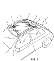
Ein Kraftfahrzeug
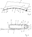
Die Wickeleinrichtung
Ein flexibles endloses Gurtband
Zum Öffnen der geschlossenen, den Dachabschnitt
Die minimale Dicke oder Höhe der Trägereinheit
Die Trägereinheit
Die Trägereinheit
Wesentliches Merkmal der erfindungsgemäßen Wickeleinrichtung
Des weiteren kann die Trägereinheit
Statt der Rückzugsfeder
Die erfindungsgemäße Rollovorrichtung eignet sich zum Abschatten an Fahrzeugdächern wie auch an Seitenfenstern, Heckfenstern oder auch an Frontscheiben.The roller blind device according to the invention is suitable for shading vehicle roofs as well as side windows, rear windows or windscreens.
Die in der Beschreibung und anhand des Ausführungsbeispiels sowie in der Zeichnung offenbarten einzelnen Merkmale der Erfindung können in beliebigen technisch zweckmäßigen Anordnungen und Gestaltungen mit dem Erfindungsgegenstand in seiner allgemeinen Form kombiniert werden.The individual features of the invention disclosed in the description and on the basis of the exemplary embodiment and in the drawing can be combined with the subject matter of the invention in its general form in any technically expedient arrangements and configurations.
BezugszeichenlisteLIST OF REFERENCE NUMBERS
- 11
- Kraftfahrzeugmotor vehicle
- 22
- Fahrzeugdachvehicle roof
- 33
- Dachabschnittroof section
- 44
- Rollovorrichtungnet device
- 55
- Rollobahnblind web
- 66
- Wickeleinrichtungwinding device
- 77
- Führungsschieneguide rail
- 88th
- Zugspriegeltension bow
- 99
- Wickelwellewinding shaft
- 1010
- Trägereinheitsupport unit
- 1111
- obere Führungsflächeupper guide surface
- 1212
- untere Führungsflächelower guide surface
- 1313
- vordere Führungsflächefront guide surface
- 1414
- hintere Führungsflächerear guide surface
- 1515
- Aussparungrecess
- 1616
- Wellensegmentwave segment
- 1717
- Verbindungswelleconnecting shaft
- 1818
- Gurtbandwebbing
- 1919
- Vorsprunghead Start
- 2020
- Drehachseaxis of rotation
- 2121
- Ausnehmungrecess
- 2222
- Innenseiteinside
- 2323
- Rückzugsfederreturn spring
ZITATE ENTHALTEN IN DER BESCHREIBUNG QUOTES INCLUDE IN THE DESCRIPTION
Diese Liste der vom Anmelder aufgeführten Dokumente wurde automatisiert erzeugt und ist ausschließlich zur besseren Information des Lesers aufgenommen. Die Liste ist nicht Bestandteil der deutschen Patent- bzw. Gebrauchsmusteranmeldung. Das DPMA übernimmt keinerlei Haftung für etwaige Fehler oder Auslassungen.This list of the documents listed by the applicant has been generated automatically and is included solely for the better information of the reader. The list is not part of the German patent or utility model application. The DPMA assumes no liability for any errors or omissions.
Zitierte PatentliteraturCited patent literature
- DE 19500367 C1 [0002] DE 19500367 C1 [0002]
Claims (14)
Priority Applications (1)
| Application Number | Priority Date | Filing Date | Title |
|---|---|---|---|
| DE202011104257U DE202011104257U1 (en) | 2011-08-11 | 2011-08-11 | Roller blind device with a winding device |
Applications Claiming Priority (1)
| Application Number | Priority Date | Filing Date | Title |
|---|---|---|---|
| DE202011104257U DE202011104257U1 (en) | 2011-08-11 | 2011-08-11 | Roller blind device with a winding device |
Publications (1)
| Publication Number | Publication Date |
|---|---|
| DE202011104257U1 true DE202011104257U1 (en) | 2011-11-09 |
Family
ID=45116291
Family Applications (1)
| Application Number | Title | Priority Date | Filing Date |
|---|---|---|---|
| DE202011104257U Expired - Lifetime DE202011104257U1 (en) | 2011-08-11 | 2011-08-11 | Roller blind device with a winding device |
Country Status (1)
| Country | Link |
|---|---|
| DE (1) | DE202011104257U1 (en) |
Cited By (1)
| Publication number | Priority date | Publication date | Assignee | Title |
|---|---|---|---|---|
| CN106515396A (en) * | 2016-11-24 | 2017-03-22 | 安徽理工大学 | Automobile skylight insect-proof device |
Citations (1)
| Publication number | Priority date | Publication date | Assignee | Title |
|---|---|---|---|---|
| DE19500367C1 (en) | 1995-01-09 | 1996-03-14 | Webasto Karosseriesysteme | Vehicle roof with swivel=open roof panel |
-
2011
- 2011-08-11 DE DE202011104257U patent/DE202011104257U1/en not_active Expired - Lifetime
Patent Citations (1)
| Publication number | Priority date | Publication date | Assignee | Title |
|---|---|---|---|---|
| DE19500367C1 (en) | 1995-01-09 | 1996-03-14 | Webasto Karosseriesysteme | Vehicle roof with swivel=open roof panel |
Cited By (1)
| Publication number | Priority date | Publication date | Assignee | Title |
|---|---|---|---|---|
| CN106515396A (en) * | 2016-11-24 | 2017-03-22 | 安徽理工大学 | Automobile skylight insect-proof device |
Similar Documents
| Publication | Publication Date | Title |
|---|---|---|
| EP1182066B1 (en) | Vehicle with roller blind in the roof | |
| DE19910830C1 (en) | Roller sunshade for vehicle roof has cords attached to lateral outer ends of roller blind fed to spool via direction changing devices near other end of roof opening, tensioning arrangement | |
| EP1449692B1 (en) | Sun shade system for a vehicle | |
| DE4481036B4 (en) | Sunshade for automotive vehicle roof - has roof bows and flexible sheet spanning between bows, all of which are slidably disposed proximate with inside surface of roof | |
| EP1006012B1 (en) | Roller blind for vehicle | |
| DE102005040758B4 (en) | The blind assembly | |
| DE102004020336C5 (en) | Car roof with a roller blind arrangement | |
| DE10331514A1 (en) | Sunshade assembly for a vehicle roof | |
| DE19834777C2 (en) | Roller blind, in particular sun protection roller blind for the transparent roof window of a motor vehicle | |
| EP1884391A2 (en) | Roller blind device and wind blocker and motor vehicle with a roller blind device | |
| DE3345503A1 (en) | Roller blind for vehicle windows | |
| DE19844779C1 (en) | Cover arrangement for opening in vehicle roof | |
| DE102009045746A1 (en) | Roller blind arrangement for use as e.g. sun protection of insulating glass window, has winding shaft with engaging elements for engaging in linear guiding elements in form-fit manner for winding and unwinding curtain element | |
| DE102015106528A1 (en) | Vehicle window shade with cable pull concept and drive of the cable pull via toothed belt | |
| DE102006028353A1 (en) | Motor vehicle window blind, has gear wheel pivoted at two positions of rigid blind web end and gear wheel intervenes into gear rack fixed to vehicle and extending toward movement of roller web during winding and unwinding | |
| EP3630514B1 (en) | Roller blind arrangement for a motor vehicle | |
| EP1870271B1 (en) | Roller blind for a vehicle window | |
| DE102008011505A1 (en) | Roller blind system for use as e.g. sun blind system, in vehicle, has force transmission unit engaging at moving profile and coupled with main line by transmission, such that movement of main line causes movement of transmission unit | |
| DE10063056C2 (en) | Sun protection arrangement for a vehicle roof | |
| EP3676117A1 (en) | Roller blind arrangement with winding shaft cladding tube | |
| EP0529591B1 (en) | Roller blind, preferably for vehicle rear windows | |
| DE102008061215A1 (en) | Motor vehicle, has roller blind wound using ropes and brought into extended position, where ropes are wound to portion of rotatable winding bodies that are fastened to shaft that is displaced by blind shaft | |
| DE102020108874A1 (en) | Darkening device for a motor vehicle, vehicle roof and motor vehicle | |
| DE102015110117B4 (en) | Roller blind arrangement with side guide for roller blinds | |
| DE102019128191B4 (en) | Shading arrangement with shading track |
Legal Events
| Date | Code | Title | Description |
|---|---|---|---|
| R207 | Utility model specification |
Effective date: 20111229 |
|
| R150 | Utility model maintained after payment of first maintenance fee after three years | ||
| R150 | Utility model maintained after payment of first maintenance fee after three years |
Effective date: 20140828 |
|
| R151 | Utility model maintained after payment of second maintenance fee after six years | ||
| R152 | Utility model maintained after payment of third maintenance fee after eight years | ||
| R071 | Expiry of right |