DE19829176B4 - Device on a packaging machine - Google Patents

Device on a packaging machine Download PDF

Info

Publication number
DE19829176B4
DE19829176B4 DE1998129176 DE19829176A DE19829176B4 DE 19829176 B4 DE19829176 B4 DE 19829176B4 DE 1998129176 DE1998129176 DE 1998129176 DE 19829176 A DE19829176 A DE 19829176A DE 19829176 B4 DE19829176 B4 DE 19829176B4
Authority
DE
Germany
Prior art keywords
transport
objects
packaging machine
along
slider
Prior art date
Legal status (The legal status is an assumption and is not a legal conclusion. Google has not performed a legal analysis and makes no representation as to the accuracy of the status listed.)
Expired - Lifetime
Application number
DE1998129176
Other languages
German (de)
Other versions
DE19829176A1 (en
Inventor
Andreas Rothbauer
Horst Rüger
Current Assignee (The listed assignees may be inaccurate. Google has not performed a legal analysis and makes no representation or warranty as to the accuracy of the list.)
BUEHLER OPTIMA MASCHF
Optima Maschinenfabrik Dr Buehler & Co GmbH
Original Assignee
BUEHLER OPTIMA MASCHF
Optima Maschinenfabrik Dr Buehler & Co GmbH
Priority date (The priority date is an assumption and is not a legal conclusion. Google has not performed a legal analysis and makes no representation as to the accuracy of the date listed.)
Filing date
Publication date
Application filed by BUEHLER OPTIMA MASCHF, Optima Maschinenfabrik Dr Buehler & Co GmbH filed Critical BUEHLER OPTIMA MASCHF
Priority to DE1998129176 priority Critical patent/DE19829176B4/en
Priority to JP11184343A priority patent/JP2000079912A/en
Publication of DE19829176A1 publication Critical patent/DE19829176A1/en
Application granted granted Critical
Publication of DE19829176B4 publication Critical patent/DE19829176B4/en
Anticipated expiration legal-status Critical
Expired - Lifetime legal-status Critical Current

Links

Classifications

    • BPERFORMING OPERATIONS; TRANSPORTING
    • B65CONVEYING; PACKING; STORING; HANDLING THIN OR FILAMENTARY MATERIAL
    • B65GTRANSPORT OR STORAGE DEVICES, e.g. CONVEYORS FOR LOADING OR TIPPING, SHOP CONVEYOR SYSTEMS OR PNEUMATIC TUBE CONVEYORS
    • B65G47/00Article or material-handling devices associated with conveyors; Methods employing such devices
    • B65G47/22Devices influencing the relative position or the attitude of articles during transit by conveyors
    • B65G47/26Devices influencing the relative position or the attitude of articles during transit by conveyors arranging the articles, e.g. varying spacing between individual articles
    • B65G47/30Devices influencing the relative position or the attitude of articles during transit by conveyors arranging the articles, e.g. varying spacing between individual articles during transit by a series of conveyors
    • B65G47/31Devices influencing the relative position or the attitude of articles during transit by conveyors arranging the articles, e.g. varying spacing between individual articles during transit by a series of conveyors by varying the relative speeds of the conveyors forming the series
    • BPERFORMING OPERATIONS; TRANSPORTING
    • B65CONVEYING; PACKING; STORING; HANDLING THIN OR FILAMENTARY MATERIAL
    • B65BMACHINES, APPARATUS OR DEVICES FOR, OR METHODS OF, PACKAGING ARTICLES OR MATERIALS; UNPACKING
    • B65B35/00Supplying, feeding, arranging or orientating articles to be packaged
    • B65B35/10Feeding, e.g. conveying, single articles
    • B65B35/24Feeding, e.g. conveying, single articles by endless belts or chains

Abstract

Einrichtung zum Zuführen von zu verpackenden Gegenständen (2) zu einer Verpackungsmaschine, mit
1.1 einer Bewegungsbahn (1), längs der die zu verpackenden Gegenstände (2) zu der Verpackungsmaschine bewegt werden,
1.2 einer ersten Transporteinrichtung (5) zum Transport von Gegenständen (2) die Bewegungsbahn (1) entlang von einer Aufgabeposition zu einer Übergabeposition für die Verpackungsmaschine, sowie mit
1.3 einer zweiten Transporteinrichtung (6) zum Transportieren von Gegenständen (2) die Bewegungsbahn (1) entlang von der Aufgabeposition zu einer Zwischenposition.
Device for feeding articles to be packaged (2) to a packaging machine, with
1.1 a movement path (1), along which the objects to be packaged (2) are moved to the packaging machine,
1.2 a first transport device (5) for the transport of objects (2) the movement path (1) along a loading position to a transfer position for the packaging machine, and with
1.3 a second transport device (6) for transporting objects (2) the movement path (1) along the task position to an intermediate position.

Figure 00000001
Figure 00000001

Description

Die Erfindung geht aus von bekannten Verpackungsmaschinen, bei denen die zu verpackenden Produkte beispielsweise mit Hilfe eines Zuführbandes der Verpackungsmaschine vereinzelt zugeführt werden. Es gibt verschiedene Anforderungen an die Anordnung der zu verpackenden Gegenstände. Diese können einreihig angeordnet werden, mehrlagig oder auch mehrreihig.The The invention is based on known packaging machines in which the products to be packaged, for example by means of a feed belt the packaging machine are supplied separately. There are different Requirements for the arrangement of the items to be packed. These can arranged in a single row, multi-layer or multi-row.

Die Reihenbildung und die Lagenbildung werden normalerweise an einer Schnittstelle zwischen einer Vorrichtung zur Stapelbildung und der Verpackungsmaschine oder in dieser durchgeführt.The Row formation and layer formation are usually at one Interface between a device for stacking and the packaging machine or performed in this.

Es ist bereits bekannt, für eine Reihenbildung vor dem Zuführband der Verpackungsmaschine ein kurzes schnellaufendes Band und eine Transferstation anzuordnen. Damit kann die Leistung der Verpackungsmaschine erhöht werden. Allerdings wird der Aufwand vergrößert.It is already known for a row formation in front of the feed belt the packaging machine a short high-speed tape and a To arrange transfer station. This can improve the performance of the packaging machine elevated become. However, the effort is increased.

Der Erfindung liegt die Aufgabe zugrunde, eine einfach aufgebaute Möglichkeit zum Zuführen von zu verpackenden Gegenständen zu einer Verpackungsmaschine zu schaffen, die eine hohe Leistung der Verpackungsmaschine möglich macht.Of the Invention is based on the object, a simple design possibility for feeding to be packed items to create a packaging machine that has a high performance of Packaging machine possible power.

Zur Lösung dieser Aufgabe schlägt die Erfindung eine Einrichtung mit den Merkmalen des Anspruchs 1 vor. Weiterbildungen der Erfindung sind Gegenstand der abhängigen Ansprüche.to solution this task strikes the invention a device with the features of claim 1 in front. Further developments of the invention are the subject of the dependent claims.

Während im Stand der Technik das zusätzliche schnellaufende Band die Gegenstände zu der Transferstation befördert, von wo aus sie von der Transferstation auf das eigentliche Zuführband übergeben werden, arbeitet jetzt die zweite Transporteinrichtung an der gleichen Bewegungsbahn, an der auch die andere Transporteinrichtung arbeitet, die die zu verpackenden Gegenstände bis zur Übergabe zu der Verpackungsmaschine bewegt.While in the Prior art, the additional fast-moving band the objects transported to the transfer station, from where they pass from the transfer station to the actual feeder conveyor Now, the second transport device is working on the same Trajectory on which the other transport device works, the items to be packed until the transfer to the packaging machine moves.

In Weiterbildung der Erfindung kann vorgesehen sein, daß die zweite über einen kürzeren Weg arbeitende Transporteinrichtung eine höhere Transportgeschwindigkeit aufweist als die erste.In Development of the invention can be provided that the second via a shorter Way transporting a higher transport speed has as the first.

In Weiterbildung der Erfindung kann vorgesehen sein, daß die beiden Transporteinrichtungen in dem Bereich von der Aufgabeposition bis zu der Zwischenposition abwechselnd an den Gegenständen angreifen. Jeder Gegenstand wird längs dieser Strecke also nur von einer Transporteinrichtung transportiert.In Further development of the invention can be provided that the two Transport facilities in the area from the loading position to to the intermediate position alternately attack on the objects. Every object gets along This distance so transported only by a transport device.

Beispielsweise kann vorgesehen sein, daß die erste Transporteinrichtung an jedem zweiten Gegenstand angreift.For example can be provided that the first transport device attacks on every other object.

Es kann aber zur weiteren Erhöhung der Leistung und zur dreireihigen Verpackung auch vorgesehen sein, daß die erste Transporteinrichtung an jedem dritten zu verpackenden Gegenstand angreift.It but can increase further performance and three-tiered packaging, that the first transport device on every third item to be packaged attacks.

Erfindungsgemäß kann vorgesehen sein, daß die Transporteinrichtungen derart ausgebildet sind, daß sie die Gegenstände vor sich her schieben.According to the invention can be provided be that the Transport devices are designed such that they objects push in front of him.

In nochmaliger Weiterbildung kann vorgesehen sein, daß die Transporteinrichtungen derart ausgebildet sind, daß sie sich gegenseitig nicht behindern.In repeated training can be provided that the transport facilities are designed so that they do not hinder each other.

Erfindungsgemäß kann vorgesehen sein, daß die Transporteinrichtungen einen Schieber zum Angriff an den Gegenständen aufweisen. Dieser Schieber kann insbesondere längs eines geschlossenen Weges bewegt werden, wobei der Rückweg längs eines anderen Weges geführt wird als der Hinweg, bei dem an den Gegenständen angegriffen wird.According to the invention can be provided be that the Transport devices have a slider for attacking the objects. This slider can in particular along a closed path be moved, the return path along a led another way is considered the way to attack the objects.

Insbesondere kann in Weiterbildung vorgesehen sein, daß der Schieber eine sich quer zu der Transportrichtung erstreckende Stange aufweist. Damit kann erreicht werden, daß der Schieber an einer nicht zu kleinen Fläche der Gegenstände angreift, so daß auch weniger stabile oder verformbare Gegenstände transportiert werden können.Especially may be provided in a development that the slider is a transversely Having to the transport direction extending rod. So that can be achieved that the Slide on a not too small area of the objects attacks, so that too less stable or deformable objects can be transported.

Insbesondere kann vorgesehen sein, daß die Stange im Bereich ihrer beiden Enden an je einer umlaufenden Kette, einem Riemen oder dergleichen befestigt ist. Dies ermöglicht in einfacher Weise eine Bewegung, bei der die Zurückführung des Schiebers an einer Stelle erfolgt, wo der Transport eines anderen Gegenstandes durch die gleiche oder die andere Transporteinrichtung nicht behindert wird.Especially can be provided that the Rod in the region of its two ends on a respective revolving chain, a belt or the like is attached. This allows in simply a movement in which the return of the slider to a Location takes place where the transport of another object through the same or the other transport device is not hindered becomes.

Um für den Fall einer Störung vorzusorgen, kann erfindungsgemäß vorgesehen sein, daß der Schieber mit einer Überlastsicherung versehen wird, die ihn im Notfall von dem Antrieb löst.Around for the Case of a fault to provide, can be provided according to the invention be that the slider with an overload protection provided, which releases it from the drive in an emergency.

In Weiterbildung kann erfindungsgemäß im Bereich der Übergabe der Gegenstände eine Einrichtung zum Vorkomprimieren der Gegenstände angeordnet werden.In Development can according to the invention in the field the handover of the objects a means for precompressing the articles are arranged.

Es folgt die Beschreibung einer bevorzugten Ausführungsform der Erfindung anhand der Zeichnung. Hierbei zeigen:It follows the description of a preferred embodiment of the invention based the drawing. Hereby show:

1 schematisch die Anordnung beider Transporteinrichtungen zum Transportieren zu der Verpackungsmaschine; 1 schematically the arrangement of both transport means for transporting to the packaging machine;

2 eine schematische Stirnansicht der Anordnung von rechts in 1; 2 a schematic end view of the arrangement from the right in 1 ;

3 in vergrößertem Maßstab die Anordnung beider Transporteinrichtungen im Bereich der Aufgabeposition; 3 on an enlarged scale, the arrangement of both transport devices in the region of the loading position;

4 in vergrößertem Maßstab die Anordnung einer Stange an einer Kette; 4 on an enlarged scale, the arrangement of a rod on a chain;

5 eine Ansicht der Anordnung der 4 von rechts. 5 a view of the arrangement of 4 from the right.

1 zeigt stark vereinfacht und schematisch die Wirkungsweise der von der Erfindung vorgeschlagenen Einrichtung. Eine Verpackungsmaschine benötigt die zu verpackenden Gegenstände mit einem Abstand voneinander, damit die Gegenstände verpackt werden können. Die Gegenstände werden längs einer Bewegungs bahn 1 der Verpackungsmaschine zugeführt, wobei es sich bei der Bewegungsbahn 1 im einfachsten Fall um eine horizontal angeordnete Platte handeln kann. Auf dieser Bewegungsbahn 1 werden die zu verpackenden Gegenstände 2 von einer Aufgabeposition, rechts in 1, zu einer Position bewegt, wo sie von der Verpackungsmaschine übernommen werden können, in der 1 ist dies der linke Bereich. Dort ist ein Schieber 3 vorhanden, der an den Gegenständen angreifen und diese in die Verpackungsmaschine einschieben kann. 1 shows greatly simplified and schematically the operation of the proposed device of the invention. A packaging machine requires the items to be packaged at a distance from each other so that the items can be packaged. The objects are moved along a movement path 1 fed to the packaging machine, it being at the trajectory 1 in the simplest case can act around a horizontally arranged plate. On this trajectory 1 become the items to be packed 2 from a posting position, right in 1 , moved to a position where they can be taken over by the packaging machine, in the 1 this is the left area. There is a slider 3 present, which can attack on the objects and insert them into the packaging machine.

Zum Transport der Gegenstände längs der Bewegungsbahn 1 ist eine erste mit einem Schieber 4 versehene Transporteinrichtung 5 vorhanden, die so ausgebildet ist, daß sie einen zu verpackenden Gegenstand 2 von der Aufgabeposition bis zu der Übergabestelle bewegen kann. Die Transporteinrichtung 5 kann mehrere Schieber 4 aufweisen, von denen in 1 nur zwei dargestellt sind.To transport the objects along the path of movement 1 is a first with a slider 4 provided transport device 5 present, which is designed so that they have an object to be packaged 2 move from the loading position to the transfer point. The transport device 5 can have several slides 4 have, of which in 1 only two are shown.

Es ist eine zweite Transporteinrichtung 6 vorhanden, die, beispielsweise ebenfalls mit Hilfe eines Schiebers 7, die Gegenstände 2 von der Aufgabeposition längs eines vorderen Teils der Bewegungsbahn 1 transportieren kann, und zwar bis in eine Zwischenposition, in der in 1 der linke Gegenstand 2 angenähert angeordnet ist. Die zweite Transporteinrichtung 6 kann eine andere Transportgeschwindigkeit als die erste Transporteinrichtung aufweisen, aber auch die gleiche. Beide Transporteinrichtungen arbeiten mit einer konstanten Umlaufgeschwindigkeit.It is a second transport device 6 present, which, for example, also with the help of a slider 7 , things 2 from the loading position along a front part of the trajectory 1 can transport, up to an intermediate position, in the in 1 the left object 2 is arranged approximately. The second transport device 6 may have a different transport speed than the first transport device, but also the same. Both transport devices operate at a constant rotational speed.

Die Wirkungsweise der in 1 dargestellten Einrichtung ist die folgende. Ein Gegenstand 2 wird von einer weiteren Vorrichtung, in der der Gegenstand 2 als Stapel aufgerichtet wird, auf die Aufgabeposition rechts in 1 aufgesetzt und von dem Schieber 7 der zweiten Transporteinrichtung 6 bis in die dargestellte Zwischenposition bewegt. Der nächste auf die Aufgabeposition gesetzte Gegenstand 2 wird von dem Schieber 4 der ersten Transporteinrichtung 5 bewegt, bis er an dem ersten Gegenstand 2 anlegt. Bei einer Weiterbewegung des Schiebers 4 schiebt also die erste Transporteinrichtung 5 eine Reihe von zwei in Transportrichtung hintereinander angeordneten Gegenständen 2 weiter. Diese beiden hintereinander angeordneten Gegenstände 2 werden dann gemeinsam verpackt.The mode of action of in 1 The device shown is the following. A thing 2 is replaced by another device in which the object 2 is erected as a stack, on the task position right in 1 put on and off the slide 7 the second transport device 6 moved to the intermediate position shown. The next item placed on the posting position 2 gets from the slider 4 the first transport device 5 moves until he reaches the first item 2 invests. Upon further movement of the slider 4 So pushes the first transport device 5 a series of two consecutively arranged in the transport direction objects 2 further. These two objects arranged one behind the other 2 are then packed together.

Die Schieber 4 der ersten Transporteinrichtung 5 und die Schieber 7 der zweiten Transporteinrichtung 6 werden beide jeweils längs eines geschlossenen Weges bewegt. Dieser Weg führt in seinem ersten Teil die Schieber 4, 7 oberhalb der Transportbahn 1 parallel zu dieser, bis er zu einer Stelle gelangt, wo kein Weitertransport gewünscht wird. Dort wird der Schieber 4, 7 durch eine Lücke 8, 9 in der Bewegungsbahn 1 nach unten geführt. Die Rückwärtsbewegung der Schieber 4, 7 zu der Ausgangsposition erfolgt also unterhalb der Bewegungsbahn 1, so daß dann wieder ein Angriff an dem nächsten Gegenstand 2 erfolgen kann.The sliders 4 the first transport device 5 and the sliders 7 the second transport device 6 Both are each moved along a closed path. This path leads in its first part the slide 4 . 7 above the transport track 1 parallel to this until it reaches a point where no further transport is desired. There is the slider 4 . 7 through a gap 8th . 9 in the movement path 1 led down. The backward movement of the slider 4 . 7 to the starting position is thus below the trajectory 1 , so that then again an attack on the next object 2 can be done.

Die geschlossene Bahn, längs der die Schieber 4, 7 bewegt werden, kann beispielsweise durch eine Kette, einen Zahnriemen, einen sonstigen Riemen oder dergleichen verwirklicht werden. Ebenfalls möglich ist eine Verschiebung in einer Nut-Führung.The closed track, along which the slides 4 . 7 can be moved, for example, by a chain, a toothed belt, another belt or the like can be realized. Also possible is a shift in a slot guide.

2 zeigt ebenfalls schematisch eine Stirnansicht der Anordnung der 1 von rechts. Der Schieber 4 der ersten Transporteinrichtung 5 ist in dem dargestellten Fall als Stange verwirklicht, die sich quer zu dem Transportweg und parallel zu der Fläche der Bewegungsbahn 1 erstreckt. Die Stange 4 ist mit ihren beiden Enden mit der Antriebseinrichtung verbunden, beispielsweise mit einem Kettenglied, wenn zum Antrieb eine umlaufende Kette verwendet wird. 2 also schematically shows an end view of the arrangement of 1 from the right. The slider 4 the first transport device 5 is realized in the illustrated case as a rod, which is transverse to the transport path and parallel to the surface of the trajectory 1 extends. The pole 4 is connected at its two ends to the drive means, for example a chain link, when a revolving chain is used to drive.

Auch die Schieber 7 der zweiten Transporteinrichtung 6 sind als Stange ausgebildet, die wiederum im Bereich ihrer beiden Enden mit dem Antrieb der Transporteinrichtung 6 verbunden ist. Diese Art der Ausbildung der Schieber hat den Vorteil, daß sie unabhängig von der Breite der Gegenstände 2 verwendet werden kann und an diesen über eine relativ große Fläche angreift.Also the slides 7 the second transport device 6 are designed as a rod, which in turn in the region of its two ends with the drive of the transport device 6 connected is. This type of training of the slide has the advantage that it is independent of the width of the items 2 can be used and attacks these over a relatively large area.

3 zeigt in vergrößertem Maßstab etwas deutlicher ausgeführt, wie die beiden Transporteinrichtungen im Bereich der Aufgabeposition der Bewegungsbahn 1 ausgebildet sein können. Die erste Transporteinrichtung 5 weist eine umlaufende Kette 10 auf, die im Bereich des vorderen Endes über zwei Zahnräder 11 umgelenkt ist. Natürlich sind zwei solche Ketten 10 vorhanden, je eine auf beiden Seiten des Weges, den die Gegenstände 2 entlang geschoben werden sollen. 3 shows on a larger scale somewhat more clearly executed, as the two transport devices in the region of the task position of the movement path 1 can be trained. The first transport device 5 has a circulating chain 10 on, in the area of the front end via two gears 11 is diverted. Of course, two are sol chains 10 present, one on each side of the path, the objects 2 to be pushed along.

An dem in 1 linken Ende sind ähnliche Zahnräder 11 angeordnet. Die Kette 10 kann über ihre Länge oberhalb und unterhalb der Bewegungsbahn 1 geführt sein.At the in 1 left end are similar gears 11 arranged. The chain 10 can be over their length above and below the trajectory 1 be guided.

Vollständig innerhalb des Verlaufs der Kette 10 ist eine zweite Kette 12 vorgesehen, die den Antrieb der zweiten Transporteinrichtung 6 bildet. Auch diese Kette 12 ist über insgesamt vier Umlenkzahnräder 13 geführt, von denen eines angetrieben ist. An der Kette 12 ist in noch zu beschreibender Weise eine den Schieber 7 bildende Stange 14 befestigt. Die auf der gleichen Seite der Bewegungsbahn angeordneten Ketten 10, 12 der ersten bzw. zweiten Transporteinrichtung 5, 6 können im übrigen in einer Ebene angeordnet sein. Die Darstellung der 2 ist aus Gründen der besseren Verständlichkeit anders gezeichnet.Completely within the course of the chain 10 is a second chain 12 provided, which drives the second transport device 6 forms. Also this necklace 12 is over a total of four Umlenkzahnräder 13 led, one of which is driven. On the chain 12 is in a manner to be described, a slider 7 forming rod 14 attached. The chains arranged on the same side of the trajectory 10 . 12 the first and second transport means 5 . 6 may otherwise be arranged in a plane. The presentation of the 2 is drawn differently for reasons of clarity.

4 zeigt in nochmals vergrößertem Maßstab die Anbringung einer einen Schieber 4, 7 bildenden Stange 14 an einer Kette 10. Die 4 ist in Zusammenhang mit der 5 zu verstehen. Ein Kettenglied ist als Winkel 15 mit einem horizontalen Flansch 16 ausgebildet. An dem horizontalen Flansch 16 ist ein Lagerbock 17 mit Hilfe zweier Schrauben 18 angeschraubt. Der Lagerbock 17 dient zum Festlegen der Stange 14. Zu diesem Zweck enthält er eine die Stange 14 über mehr als einen halben Umfang umfassende Ausnehmung, in die die Stange 14 durch eine an den Lagerbock 17 angeschraubte Zungenfeder 28 gedrückt wird. Die Zungenfeder 28 greift an einem Teil der Stange 14 mit verringertem Durchmesser an. 4 shows on a further enlarged scale the attachment of a slide 4 . 7 forming rod 14 on a chain 10 , The 4 is in connection with the 5 to understand. A chain link is as an angle 15 with a horizontal flange 16 educated. On the horizontal flange 16 is a bearing block 17 with the help of two screws 18 screwed. The bearing block 17 serves to fix the pole 14 , For this purpose he contains a pole 14 over more than half a circumference comprehensive recess in which the rod 14 by one to the bearing block 17 bolted tongue spring 28 is pressed. The tongue feather 28 grabs a part of the pole 14 with reduced diameter.

Die Ausnehmung, in die die Stange 14 durch die Feder 28 gedrückt wird, ist in Gegenrichtung zur Transportrichtung der jeweiligen Transporteinrichtung 5, 6 offen, d. h. in 1 nach rechts. Die Stange 14 könnte auch nach oben entnommen werden, dies wird jedoch durch einen Winkel 19 verhindert, der ebenfalls an dem Lagerbock 17 angeschraubt ist und dessen oberer Schenkel parallel zu der Transportrichtung verläuft. Nimmt man an, daß die Kette 10 in 4 nach links bewegt wird und daß die Stange 14 gegen einen festen Anschlag aufläuft, so kann sie unter Überwindung der Kraft der Feder 18 nach rechts aus dem Lagerbock 17 herausgedrückt werden. Die Anbringung mit Hilfe einer Feder 28 in einer Ausnehmung des Lagerbocks 17 bildet also eine Überlastsicherung für den Fall von Störungen im Ablauf des Betriebs der Vorrichtung.The recess into which the rod 14 through the spring 28 is pressed, is in the opposite direction to the transport direction of the respective transport device 5 . 6 open, ie in 1 to the right. The pole 14 could also be taken up, but this is by an angle 19 prevented, also on the bearing block 17 is bolted and whose upper leg is parallel to the transport direction. Suppose that the chain 10 in 4 is moved to the left and that the rod 14 it runs against a firm stop, so it can overcome the force of the spring 18 to the right from the bearing block 17 be pushed out. The attachment by means of a spring 28 in a recess of the bearing block 17 Thus forms an overload protection in the event of disturbances in the course of operation of the device.

Der durch die Stange 14 gebildete Schieber ist so aufgebaut, daß die Stange 14 ein Rohr 20 aufweist, in dessen beide Enden je ein Achszapfen 21 eingesetzt ist. Das äußere Ende des Achszapfens 21 weist einen Abschnitt 22 verringerten Durchmessers auf, an dem die Feder 28 angreifen kann. Der Abschnitt 22 verringerten Durchmessers dient ebenfalls zur Festlegung der Stange 14 in axialer Richtung. Durch die Anbringung der Halterung an einem Kettenglied kann der Schieber problemlos die Richtungsänderungen durchführen.The one by the pole 14 formed slide is constructed so that the rod 14 a pipe 20 has, in the two ends depending on a journal 21 is used. The outer end of the axle journal 21 has a section 22 reduced diameter on which the spring 28 can attack. The section 22 reduced diameter is also used to determine the rod 14 in the axial direction. By attaching the bracket to a chain link, the slider can easily make the changes in direction.

Aus der vereinfachten Darstellung der 1 und der 3 ist zu entnehmen, daß im dargestellten Ausführungsbeispiel die Kette der zweiten Transporteinrichtung sich längs eines Weges bewegt, der vollständig innerhalb des Weges liegt, der von der Kette der ersten Transporteinrichtung zurückgelegt wird. Unter Bezugnahme auf die 2 wurde erwähnt, daß die Ketten auf beiden Seiten der Transportbahn 1 dennoch in einer Ebene liegen können.From the simplified representation of 1 and the 3 It can be seen that in the illustrated embodiment, the chain of the second transport means moves along a path which is completely within the path, which is covered by the chain of the first transport means. With reference to the 2 it was mentioned that the chains on both sides of the transport path 1 still be in one plane.

Erfindungsgemäß kann auch vorgesehen sein, daß die Schieber 4 der ersten Transporteinrichtung 5 und die Schieber 7 der zweiten Transporteinrichtung längs der Bewegungsbahn 1 in einer Ebene angeordnet sind, d. h. auf einer Höhe. Die 2 ist, wie bereits erwähnt, anders dargestellt, um die Schieber einzeln erkennen zu lassen. Die Möglichkeit, die Schieber der beiden Transporteinrichtungen auf der gleichen Höhe anzuordnen, kann dadurch erreicht werden, daß die in 4 dargestellte Einrichtung bei der oberen Kette in deren oberem Trum nach unten orientiert wird, während sie bei der unteren Kette in deren oberem Trum nach oben orientiert ist. Dadurch können die Schieber 4, 7 auf gleicher Höhe gegenüber der Bewegungsbahn 1 angeordnet werden. Dies hat den Vorteil, daß der Spalt zwischen der Oberseite der Transportbahn 1 und den Schiebern klein gehalten wird. Die Einrichtung ist daher auch für Verpackungsstapel mit geringer Höhe anwendbar.According to the invention can also be provided that the slide 4 the first transport device 5 and the sliders 7 the second transport device along the path of movement 1 arranged in a plane, ie at a height. The 2 is, as already mentioned, shown differently in order to recognize the slides individually. The possibility of arranging the slide of the two transport devices at the same height, can be achieved by the in 4 shown device is oriented at the upper chain in the upper strand down, while it is oriented at the lower chain in the upper strand upwards. This allows the slides 4 . 7 at the same height to the trajectory 1 to be ordered. This has the advantage that the gap between the top of the transport path 1 and the sliders is kept small. The device is therefore also applicable for pack stacks with low height.

Claims (14)

Einrichtung zum Zuführen von zu verpackenden Gegenständen (2) zu einer Verpackungsmaschine, mit 1.1 einer Bewegungsbahn (1), längs der die zu verpackenden Gegenstände (2) zu der Verpackungsmaschine bewegt werden, 1.2 einer ersten Transporteinrichtung (5) zum Transport von Gegenständen (2) die Bewegungsbahn (1) entlang von einer Aufgabeposition zu einer Übergabeposition für die Verpackungsmaschine, sowie mit 1.3 einer zweiten Transporteinrichtung (6) zum Transportieren von Gegenständen (2) die Bewegungsbahn (1) entlang von der Aufgabeposition zu einer 
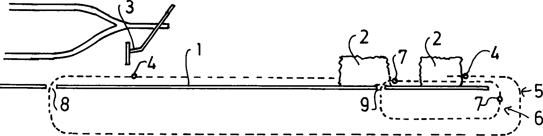
Zwischenposition.Device for feeding articles to be packaged ( 2 ) to a packaging machine, with 1.1 of a trajectory ( 1 ) along which the articles to be packaged ( 2 ) are moved to the packaging machine, 1.2 a first transport device ( 5 ) for the transport of objects ( 2 ) the trajectory ( 1 ) along a feed position to a transfer position for the packaging machine, as well as 1.3 a second transport device ( 6 ) for transporting objects ( 2 ) the trajectory ( 1 ) along the loading position to an intermediate position. Einrichtung nach Anspruch 1, bei der die zweite Transporteinrichtung (6) eine höhere Transportgeschwindigkeit aufweist als die erste (5).Device according to Claim 1, in which the second transport device ( 6 ) has a higher transport speed than the first ( 5 ). Einrichtung nach Anspruch 1 oder 2, bei der die beiden Transporteinrichtungen (5, 6) von der Aufgabeposition bis zu der Zwischenposition abwechselnd an den Gegenständen (2) angreifen.Device according to Claim 1 or 2, in which the two transport devices ( 5 . 6 ) from the loading position to the intermediate position alternately on the objects ( 2 attack). Einrichtung nach einem der vorhergehenden Ansprüche, bei der die erste Transporteinrichtung (5) an jedem zweiten Gegenstand (2) angreift.Device according to one of the preceding claims, in which the first transport device ( 5 ) on every second item ( 2 ) attacks. Einrichtung nach einem der Ansprüche 1 – 3, bei der die erste Transporteinrichtung (5) an jedem dritten Gegenstand (2) angreift.Device according to one of Claims 1 to 3, in which the first transport device ( 5 ) on every third item ( 2 ) attacks. Einrichtung nach einem der vorhergehenden Ansprüche, bei der mindestens eine Transporteinrichtung (5, 6) derart ausgebildet ist, daß sie an den Gegenständen (2) schiebend angreift.Device according to one of the preceding claims, in which at least one transport device ( 5 . 6 ) is formed so that it on the objects ( 2 ) pushing. Einrichtung nach einem der vorhergehenden Ansprüche, bei der die beiden Transporteinrichtungen (5, 6) derart ausgebildet sind, daß sie sich nicht gegenseitig behindern.Device according to one of the preceding claims, in which the two transport devices ( 5 . 6 ) are formed such that they do not interfere with each other. Einrichtung nach einem der vorhergehenden Ansprüche, bei der mindetens eine der beiden Transporteinrichtungen (5, 6) einen Schieber (4, 7) zum Angriff an den Gegenständen (2) aufweist.Device according to one of the preceding claims, wherein at least one of the two transport devices ( 5 . 6 ) a slider ( 4 . 7 ) to attack the objects ( 2 ) having. Einrichtung nach Anspruch 8, bei der der Schieber (4, 7) längs eines geschlossenen Weges bewegt wird.Device according to claim 8, in which the slider ( 4 . 7 ) is moved along a closed path. Einrichtung nach Anspruch 8 oder 9, bei der mindestens ein Schieber (4, 7) eine sich quer zu der Transportrichtung erstreckende Stange (14) aufweist.Device according to claim 8 or 9, wherein at least one slide ( 4 . 7 ) a transversely to the transport direction extending rod ( 14 ) having. Einrichtung nach einem der Ansprüche 8 bis 10, bei der der Schieber (4, 7) im Bereich beider Enden an je einer umlaufenden Kette (10, 12), einem Riemen oder dergleichen befestigt ist.Device according to one of Claims 8 to 10, in which the slider ( 4 . 7 ) in the region of both ends on a respective revolving chain ( 10 . 12 ), a belt or the like is attached. Einrichtung nach einem der vorhergehenden Ansprüche, bei der mindetens eine Transporteinrichtung (5, 6) mit einer Überlastsicherung versehen ist.Device according to one of the preceding claims, wherein at least one transport device ( 5 . 6 ) is provided with an overload protection. Einrichtung nach einem der vorhergehenden Ansprüche, mit einer Vorkomprimiereinrichtung im Bereich der Übergabe der Gegenstände (2).Device according to one of the preceding claims, with a pre-compressing device in the area of the transfer of the objects ( 2 ). Einrichtung nach einem der vorhergehenden Ansprüche, bei der die beiden Transporteinrichtungen (5, 6) an den Gegenständen (2) in der gleichen Höhe gegenüber der Bewegungsbahn (1) angreifen.Device according to one of the preceding claims, in which the two transport devices ( 5 . 6 ) on the objects ( 2 ) at the same height to the trajectory ( 1 attack).
DE1998129176 1998-06-30 1998-06-30 Device on a packaging machine Expired - Lifetime DE19829176B4 (en)

Priority Applications (2)

Application Number Priority Date Filing Date Title
DE1998129176 DE19829176B4 (en) 1998-06-30 1998-06-30 Device on a packaging machine
JP11184343A JP2000079912A (en) 1998-06-30 1999-06-29 Apparatus for packaging machine

Applications Claiming Priority (1)

Application Number Priority Date Filing Date Title
DE1998129176 DE19829176B4 (en) 1998-06-30 1998-06-30 Device on a packaging machine

Publications (2)

Publication Number Publication Date
DE19829176A1 DE19829176A1 (en) 2000-01-05
DE19829176B4 true DE19829176B4 (en) 2006-07-27

Family

ID=7872507

Family Applications (1)

Application Number Title Priority Date Filing Date
DE1998129176 Expired - Lifetime DE19829176B4 (en) 1998-06-30 1998-06-30 Device on a packaging machine

Country Status (2)

Country Link
JP (1) JP2000079912A (en)
DE (1) DE19829176B4 (en)

Families Citing this family (6)

* Cited by examiner, † Cited by third party
Publication number Priority date Publication date Assignee Title
DE102006033512B4 (en) * 2006-07-20 2008-11-06 Khs Ag Treatment machine for bottles or similar containers
WO2008098340A1 (en) 2007-02-16 2008-08-21 Countlab Inc. A container filling machine
US8006468B2 (en) 2008-04-14 2011-08-30 Countlab Inc. Container filling machine having vibration trays
CA2686751C (en) 2008-12-02 2017-02-21 Countlab, Inc. A discrete article spacing apparatus for vibration trays
US20130042943A1 (en) 2011-08-18 2013-02-21 Countlab, Inc. Container filling machine
US9434487B2 (en) 2011-09-30 2016-09-06 Countlab, Inc Container filling machine

Citations (11)

* Cited by examiner, † Cited by third party
Publication number Priority date Publication date Assignee Title
US2088269A (en) * 1935-02-25 1937-07-27 Nat Bread Wrapping Machine Co Wrapping machine
DE1025782B (en) * 1953-01-21 1958-03-06 Forsters Machine Company Ltd Method and device for packaging soft, sticky and easily deformable tablet-like objects
DE1134924B (en) * 1960-09-09 1962-08-16 Holstein & Kappert Maschf Machine for packing or unpacking bottles
DE1136628B (en) * 1959-10-15 1962-09-13 Otto Haensel Junior G M B H Sp Feeding device for a chocolate bar wrapping machine
US3206001A (en) * 1964-01-10 1965-09-14 Diamond Int Corp Support plate for conveyors
DE1761695A1 (en) * 1968-06-26 1971-08-05 Hauni Werke Koerber & Co Kg Feeding device for packing machines
DE2346407A1 (en) * 1972-09-15 1974-03-21 Mario Cavanna DEVICE FOR REGULATING THE FEEDING OF OBJECTS TO A PACKAGING MACHINE
DE2555081A1 (en) * 1974-12-19 1976-07-01 Sapal Plieuses Automatiques DEVICE FOR INTERMITTING A ROW OF OBJECTS IN AN ENDLESS CHAIN AND FOR CONTINUOUS DEPLOYMENT OF THE OBJECTS
DE3339793A1 (en) * 1982-11-05 1984-05-10 Baker Perkins Holdings PLC, Peterborough, Cambridgeshire Feeding device and method
DE2334198C2 (en) * 1972-07-07 1985-09-05 Michels S.A., Ile Saint Denis Conveyor device for packaging machines
DE4435981A1 (en) * 1994-10-08 1996-04-11 Buehler Optima Maschf Device for conveying product into packaging machine

Patent Citations (11)

* Cited by examiner, † Cited by third party
Publication number Priority date Publication date Assignee Title
US2088269A (en) * 1935-02-25 1937-07-27 Nat Bread Wrapping Machine Co Wrapping machine
DE1025782B (en) * 1953-01-21 1958-03-06 Forsters Machine Company Ltd Method and device for packaging soft, sticky and easily deformable tablet-like objects
DE1136628B (en) * 1959-10-15 1962-09-13 Otto Haensel Junior G M B H Sp Feeding device for a chocolate bar wrapping machine
DE1134924B (en) * 1960-09-09 1962-08-16 Holstein & Kappert Maschf Machine for packing or unpacking bottles
US3206001A (en) * 1964-01-10 1965-09-14 Diamond Int Corp Support plate for conveyors
DE1761695A1 (en) * 1968-06-26 1971-08-05 Hauni Werke Koerber & Co Kg Feeding device for packing machines
DE2334198C2 (en) * 1972-07-07 1985-09-05 Michels S.A., Ile Saint Denis Conveyor device for packaging machines
DE2346407A1 (en) * 1972-09-15 1974-03-21 Mario Cavanna DEVICE FOR REGULATING THE FEEDING OF OBJECTS TO A PACKAGING MACHINE
DE2555081A1 (en) * 1974-12-19 1976-07-01 Sapal Plieuses Automatiques DEVICE FOR INTERMITTING A ROW OF OBJECTS IN AN ENDLESS CHAIN AND FOR CONTINUOUS DEPLOYMENT OF THE OBJECTS
DE3339793A1 (en) * 1982-11-05 1984-05-10 Baker Perkins Holdings PLC, Peterborough, Cambridgeshire Feeding device and method
DE4435981A1 (en) * 1994-10-08 1996-04-11 Buehler Optima Maschf Device for conveying product into packaging machine

Also Published As

Publication number Publication date
JP2000079912A (en) 2000-03-21
DE19829176A1 (en) 2000-01-05

Similar Documents

Publication Publication Date Title
EP0795497B1 (en) Conveyor system for separating articles
EP2826735B1 (en) Adjustable storage section of a conveyor device and method for the intermediate storage of items
DE19522189A1 (en) Grouping and buffering device
DE2110198A1 (en) General purpose grouping device for a system for packing and unpacking objects in and out of a box
DE1802760A1 (en) Stacking device for printing works, especially newspapers
EP3381842B1 (en) Conveyor device for combining piece goods from multiple feed belts
DE4211658A1 (en) Feed device for boards
DE10301178A1 (en) Alignment and distribution device
EP0623407A1 (en) Device for vertically positioning of can bodies
WO2003022716A1 (en) Distribution device
EP0271742A2 (en) Unloading method for a cable-making installation, and apparatus therefor
DE19829176B4 (en) Device on a packaging machine
EP1291305A1 (en) Distribution device
WO2005040020A1 (en) Device for forming piles
DE3423479A1 (en) METHOD AND DEVICE FOR SEPARATING GROUPS OF DISC-SHAPED OBJECTS FROM A STACK TO BE USED AS A CURRENT
EP1771360B1 (en) Transport device
DE1623178C3 (en) Device for sorting coins and similar disc-shaped objects
DE4412686A1 (en) Equipment to arrange bottles on conveyor into separate lines
DE2653895A1 (en) CONVEYOR DEVICE FOR CHOOSING TRANSPORT TRAILS
DE2324014A1 (en) CONVEYOR DEVICE
EP1148014A2 (en) Device for forming piles
DE102017120700A1 (en) Transport device and transport method with such a transport device
DE3404694C2 (en)
DE102017110210A1 (en) Roll bar centering device for a continuous carpet press carpet roll table, roller bar carpet, continuous press, and method of centering roll bars of a roll bar carpet
EP1320432B1 (en) Transfer device

Legal Events

Date Code Title Description
8101 Request for examination as to novelty
8105 Search report available
8110 Request for examination paragraph 44
8364 No opposition during term of opposition
R071 Expiry of right