DE102012213857A1 - Fluid actuated spring - Google Patents
Fluid actuated spring Download PDFInfo
- Publication number
- DE102012213857A1 DE102012213857A1 DE201210213857 DE102012213857A DE102012213857A1 DE 102012213857 A1 DE102012213857 A1 DE 102012213857A1 DE 201210213857 DE201210213857 DE 201210213857 DE 102012213857 A DE102012213857 A DE 102012213857A DE 102012213857 A1 DE102012213857 A1 DE 102012213857A1
- Authority
- DE
- Germany
- Prior art keywords
- compression element
- closed ring
- seal
- housing
- fluid
- Prior art date
- Legal status (The legal status is an assumption and is not a legal conclusion. Google has not performed a legal analysis and makes no representation as to the accuracy of the status listed.)
- Pending
Links
Images

Classifications
-
- F—MECHANICAL ENGINEERING; LIGHTING; HEATING; WEAPONS; BLASTING
- F16—ENGINEERING ELEMENTS AND UNITS; GENERAL MEASURES FOR PRODUCING AND MAINTAINING EFFECTIVE FUNCTIONING OF MACHINES OR INSTALLATIONS; THERMAL INSULATION IN GENERAL
- F16F—SPRINGS; SHOCK-ABSORBERS; MEANS FOR DAMPING VIBRATION
- F16F9/00—Springs, vibration-dampers, shock-absorbers, or similarly-constructed movement-dampers using a fluid or the equivalent as damping medium
- F16F9/32—Details
- F16F9/36—Special sealings, including sealings or guides for piston-rods
Abstract
Mit Fluid (2) betätigte Feder (1), umfassend ein Gehäuse (3), aufweisend eine interne Kammer (4), in die ein Fluid (2) eingefüllt ist, ein Kompressionselement (8), verschiebbar montiert am Gehäuse (3), und eine Dichtung (11) des Fluids (2), eingesetzt zwischen dem Gehäuse (3) und dem Kompressionselement (8), um das Ausströmen des Fluids (2) aus der internen Kammer (4) zu vermeiden. Erfindungsgemäß umfasst die Feder (1) mindestens einen geschlossenen Ring (13), umgebend das Kompressionselement (8) und fest verbunden mit dem Gehäuse (3). Dieser geschlossene Ring (13) ist zumindest während des Verschiebens des Kompressionselements (8) im Anschlag gegen die Dichtung (11) positioniert, sodass deren Verformung begrenzt wird.A fluid (2) actuated spring (1) comprising a housing (3) comprising an internal chamber (4) into which a fluid (2) is filled, a compression element (8) slidably mounted on the housing (3), and a seal (11) of the fluid (2) interposed between the housing (3) and the compression element (8) to prevent the outflow of the fluid (2) from the internal chamber (4). According to the invention, the spring (1) comprises at least one closed ring (13), surrounding the compression element (8) and fixedly connected to the housing (3). This closed ring (13) is at least during the displacement of the compression element (8) in abutment against the seal (11) positioned so that their deformation is limited.
Description
Diese Erfindung betrifft eine mit Fluid betätigte Feder. Insbesondere handelt es sich bei dem für diese Erfindung eingesetzten Fluid um ein Inertgas. Vorzugsweise wird diese Erfindung im Bereich der Maschinen zur Formgebung von Kunststoffen und Blech verwendet, um der Presse, die diese Formgebung vornimmt, eine bestimmte Festigkeit zu verleihen.This invention relates to a fluid actuated spring. In particular, the fluid used for this invention is an inert gas. Preferably, this invention is used in the field of plastics and sheet metal forming machines to impart a certain strength to the press making this molding.
Gemäß dem Stand der Technik umfasst eine Gasfeder in der Regel ein Gehäuse, aufweisend eine interne Kammer, in die das Gas eingefüllt ist. Zusätzlich umfasst die Gasfeder eine verschiebbar in die interne Kammer eingesetzte Kolbenstange, die auf das Gas wirkt.According to the prior art, a gas spring usually comprises a housing, comprising an internal chamber, in which the gas is filled. Additionally, the gas spring includes a piston rod slidably inserted into the internal chamber which acts on the gas.
Äußerlich wirkt die Gasfeder wie eine herkömmliche Schraubenfeder und entwickelt eine Kraft, die der, mit der sie beansprucht wird, entgegenwirkt. Bei der Gasfeder steht die Kraft jedoch in Verbindung mit der Kompression und Ausdehnung des in der internen Kammer enthaltenen Gases. Praktisch wird das Gas durch das Senken der Kolbenstange komprimiert (Feder gespannt), während es sich beim Ausschub der Kolbenstange ausdehnt und in den anfänglichen Zustand zurückkehrt.Externally, the gas spring acts like a conventional coil spring and develops a force that counteracts that with which it is claimed. However, with the gas spring, the force is related to the compression and expansion of the gas contained in the internal chamber. Practically, the gas is compressed by lowering the piston rod (spring tensioned), while it expands during the extension of the piston rod and returns to the initial state.
Zudem umfasst eine Gasfeder in der Regel eine Dichtung, die zwischen dem Gehäuse und der Kolbenstange eingesetzt ist, um zu vermeiden, dass das Gas aus der Kammer ausströmt und die Entspannung der Feder bewirkt.In addition, a gas spring usually comprises a seal which is inserted between the housing and the piston rod, to avoid that the gas flows out of the chamber and causes the relaxation of the spring.
Bei dieser Dichtung handelt es sich normalerweise um einen rund um die Kolbenstange angeordneten Ring. Die Dichtung ist zudem mindestens teilweise fest mit dem Gehäuse verbunden, sodass sie während der Verschiebung der Kolbenstange fest an ihrer Position bleibt.This seal is usually a ring located around the piston rod. The seal is also at least partially fixed to the housing, so that it remains firmly in position during the displacement of the piston rod.
Diese Technik weist jedoch einige Nachteile auf.However, this technique has some disadvantages.
Die Verschiebung der Kolbenstange auf der Dichtung und die entsprechende erzeugte Hitze führen mit der Zeit zu einer Verformung (allgemein als „Extrusion” bezeichnet) der Dichtung mit entsprechenden Gasleckagen. Entsprechend bewirkt die Verformung der Dichtung die Entladung der Feder und macht diese unwirksam.The displacement of the piston rod on the seal and the corresponding heat generated over time lead to deformation (commonly referred to as "extrusion") of the seal with corresponding gas leaks. Accordingly, the deformation of the seal causes the discharge of the spring and makes it ineffective.
Um die Feder wiederverwenden zu können, besteht die Notwendigkeit, die verformte Dichtung durch eine neue zu ersetzen und neues Gas in die Kammer einzufüllen. Dieser Vorgang beinhaltet natürlich einen erheblichen Zeitaufwand und somit Geldverlust.In order to reuse the spring, there is a need to replace the deformed seal with a new one and to introduce new gas into the chamber. Of course, this process involves a considerable amount of time and money.
Angesichts dieser Situation hat diese Erfindung die Aufgabe, eine mit Fluid betätigte Feder bereitzustellen, mit der die Nachteile des Stands der Technik beseitigt werden.In view of this situation, this invention has the object to provide a fluid-operated spring, which eliminates the disadvantages of the prior art.
Insbesondere hat diese Erfindung die Aufgabe, eine mit Fluid betätigte Feder bereitzustellen, deren Nutzdauer über der des Stands der Technik liegt.In particular, this invention has the object to provide a fluid actuated spring whose useful life is above that of the prior art.
Eine weitere Aufgabe dieser Erfindung ist es insbesondere, eine mit Fluid betätigte Feder bereitzustellen, die die Verformung der Dichtung vermeidet.A further object of this invention is, in particular, to provide a fluid actuated spring which avoids deformation of the seal.
Diese Aufgaben werden im Wesentlichen durch eine mit Fluid betätigte Feder gemäß der Beschreibung in den beigefügten Patentansprüchen gelöst.These objects are essentially achieved by a fluid operated spring as described in the appended claims.
Weitere Merkmale und Vorteile dieser Erfindung ergeben sich deutlicher aus der detaillierten Beschreibung einiger bevorzugter, jedoch nicht ausschließlicher Ausführungsformen einer mit Fluid betätigten Feder, die in den beigefügten Zeichnungen dargestellt ist. Es zeigen:Other features and advantages of this invention will become more apparent from the detailed description of some preferred but not exclusive embodiments of a fluid actuated spring shown in the accompanying drawings. Show it:
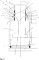
Unter Bezugnahme auf die genannten Figuren wurde mit der Bezugsnummer
Insbesondere umfasst die mit Fluid
In der bevorzugten Ausführungsform, die als Beispiel in
In einer alternativen Ausführungsform bildet der Bodenabschnitt
Die mit Fluid
Mit anderen Worten ist das Kompressionselement
Vorteilhafterweise verlaufen die Spannungsrichtung C und die Ausdehnungsrichtung E parallel zueinander. Vorzugsweise verlaufen die Spannungsrichtung C und die Ausdehnungsrichtung E parallel zur Entwicklungsachse S des Gehäuses
Wie aus den beigefügten Figuren ersichtlich wird, umfasst das Kompressionselement
Mit anderen Worten weist dieser erweiterte Abschnitt
Es wird darauf hingewiesen, dass der erweiterte Abschnitt
In der bevorzugten Ausführungsform, die als Beispiel in
Die mit Fluid
Insbesondere ist das in die interne Kammer
Vorzugsweise handelt es sich bei diesem Fluid
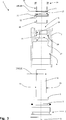
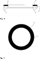
Zusätzlich umfasst die mit Fluid
Genauer gesagt weist die Dichtung
Vorteilhafterweise befindet sich die Dichtung
In der als Beispiel in
Vorteilhafterweise verleihen die Vorsprünge
Die Dichtung
In einer alternativen in
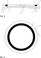
Erfindungsgemäß umfasst die mit Fluid
Mit anderen Worten ist der geschlossene Ring
Insbesondere ist der geschlossene Ring
Wie in
Mit anderen Worten definiert das Gehäuse
Praktisch bedeckt der geschlossene Ring
In diesem Fall ist die Breite des geschlossenen Rings
Es wird darauf hingewiesen, dass der Wert der Breite des geschlossenen Rings
In einer in den
Praktisch bedeckt der geschlossene Ring
Insbesondere weist die Dichtung
Es ist darauf hinzuweisen, dass der geschlossene Ring
Dieser Kontaktabschnitt
In der in
Erfindungsgemäß ist der geschlossene Ring
In der bevorzugten Ausführungsform weist der geschlossene Ring
In den
Insbesondere ist dieser Positionierungssitz
Vorzugsweise ist der geschlossene Ring
Im Detail handelt es sich bei dem Material, aus dem der geschlossene Ring
Vorteilhafterweise verleiht dieses Material dem geschlossenen Ring
Der Verformungsschutzring weist vorzugsweise eine Höhe, gemessen entlang der Ausdehnungsrichtung E des Kompressionselements
Zudem ermöglicht diese Höhe dem geschlossenen Ring
Die mit Fluid
Schließlich umfasst die Feder
Diese Erfindung löst die ihr zugrundeliegenden Aufgaben. Insbesondere ermöglicht diese Erfindung die Realisierung einer mit Fluid
Der geschlossene Ring
Der geschlossene Ring
Zusätzlich umfasst der geschlossene Ring
Es ist zudem darauf hinzuweisen, dass diese Erfindung relativ einfach zu realisieren ist und auch die in Verbindung mit der Durchführung der Erfindung stehenden Kosten nicht sehr hoch sind.It should also be noted that this invention is relatively easy to implement and also the costs involved in carrying out the invention are not very high.
Claims (10)
Applications Claiming Priority (2)
| Application Number | Priority Date | Filing Date | Title |
|---|---|---|---|
| IT000171A ITVR20110171A1 (en) | 2011-08-22 | 2011-08-22 | FLUID SPRING |
| ITVR2011A000171 | 2011-08-22 |
Publications (1)
| Publication Number | Publication Date |
|---|---|
| DE102012213857A1 true DE102012213857A1 (en) | 2013-02-28 |
Family
ID=44899279
Family Applications (1)
| Application Number | Title | Priority Date | Filing Date |
|---|---|---|---|
| DE201210213857 Pending DE102012213857A1 (en) | 2011-08-22 | 2012-08-06 | Fluid actuated spring |
Country Status (5)
| Country | Link |
|---|---|
| US (1) | US8960388B2 (en) |
| JP (1) | JP6092544B2 (en) |
| CN (1) | CN102954140B (en) |
| DE (1) | DE102012213857A1 (en) |
| IT (1) | ITVR20110171A1 (en) |
Families Citing this family (3)
| Publication number | Priority date | Publication date | Assignee | Title |
|---|---|---|---|---|
| US20160131217A1 (en) * | 2013-12-04 | 2016-05-12 | Kayaba Industry Co., Ltd. | Damper |
| CN104481964B (en) * | 2014-11-20 | 2017-01-04 | 大连光洋科技集团有限公司 | A kind of pressurize push-and-pull cylinder and the clamping device of application thereof |
| CN105686460A (en) * | 2016-01-26 | 2016-06-22 | 叶兴群 | Pipe net type mattress with uniform supporting force |
Family Cites Families (30)
| Publication number | Priority date | Publication date | Assignee | Title |
|---|---|---|---|---|
| DE2845920B1 (en) * | 1978-10-21 | 1980-03-06 | Lorenz Gmbh | Seal for reciprocating machine elements |
| US4342448A (en) * | 1980-04-04 | 1982-08-03 | Wallis Bernard J | Gas-operated cylinder |
| US4765227A (en) * | 1982-05-28 | 1988-08-23 | Teledyne Hyson | Die cylinder assembly |
| DE3245338C2 (en) * | 1982-12-08 | 1985-10-31 | Fa. Carl Freudenberg, 6940 Weinheim | poetry |
| US4693343A (en) * | 1985-06-12 | 1987-09-15 | Quadion Corporation | Multi-lobed rectangular sealing ring |
| DE3833966A1 (en) * | 1988-10-06 | 1990-04-12 | Stabilus Gmbh | SEALING ARRANGEMENT WITH LOW BOLTING FORCE |
| CN2042531U (en) * | 1988-10-17 | 1989-08-09 | 北京医疗设备四厂 | Stretching air spring |
| GB8925358D0 (en) * | 1989-11-09 | 1989-12-28 | Hallite Seals Int Ltd | Buffer seals |
| US5007276A (en) * | 1990-05-09 | 1991-04-16 | Teledyne Industries, Inc. | Seal arrangement for use in a press assembly |
| US5265852A (en) * | 1991-10-01 | 1993-11-30 | Die, Mold & Automation Components, Inc. | Gas spring with gas passageways in the assembly housing and piston rod |
| US5339932A (en) * | 1993-08-02 | 1994-08-23 | Teledyne Hyson | Apparatus and method to cushion movement of a member |
| US5437436A (en) * | 1993-08-20 | 1995-08-01 | Ni-Tech, Inc. | Stand-alone gas spring |
| US5344125A (en) * | 1993-09-17 | 1994-09-06 | Diebolt International, Inc. | Gas spring with filler valve |
| US6290235B1 (en) * | 1997-07-02 | 2001-09-18 | Parker-Hannifin Corporation | Sealing system for a reciprocating shaft |
| US6113108A (en) * | 1998-03-11 | 2000-09-05 | Caterpillar Inc. | Buffer seal |
| JPH11270691A (en) * | 1998-03-18 | 1999-10-05 | Nok Corp | Sealing device |
| KR100615662B1 (en) * | 1999-06-08 | 2006-08-25 | 트렐레보그 씰링 솔루션즈 덴마크 에이/에스 | A sealing arrangement and a sealing member therefor |
| US6595524B1 (en) * | 2000-09-25 | 2003-07-22 | Macrotech Polyseal, Inc. | Pressure regulating buffer seal |
| US6905124B2 (en) * | 2001-08-15 | 2005-06-14 | Trostel Ltd. | Unitized seal for a gas spring |
| US20050171248A1 (en) * | 2004-02-02 | 2005-08-04 | Yanmei Li | Hydrogel for use in downhole seal applications |
| JP2005337440A (en) * | 2004-05-28 | 2005-12-08 | Kayaba Ind Co Ltd | Sealing structure and sealing structure of hydraulic cylinder |
| CN2725624Y (en) * | 2004-09-16 | 2005-09-14 | 重庆工学院 | Nitrogen spring possessing high reliability dynamic sealing structure |
| US7341258B2 (en) * | 2004-09-24 | 2008-03-11 | Greene, Tweed Of Delaware, Inc. | Cammed seal assembly with sealing ring having an angled leg portion and foot portion with elastomeric energizer element |
| JP2006226455A (en) * | 2005-02-18 | 2006-08-31 | Sakagami Seisakusho Ltd | Scraper |
| EP1959171B1 (en) * | 2005-12-06 | 2018-09-12 | NOK Corporation | Rod sealing system |
| JP2008144784A (en) * | 2006-12-06 | 2008-06-26 | Nok Corp | Packing and sealing system |
| JP5102638B2 (en) * | 2008-01-21 | 2012-12-19 | 株式会社小松製作所 | Dust seal system |
| JP2010196751A (en) * | 2009-02-24 | 2010-09-09 | Nok Corp | Sealing device |
| JP5180153B2 (en) * | 2009-06-23 | 2013-04-10 | カヤバ工業株式会社 | Air spring structure |
| KR101363961B1 (en) * | 2009-09-09 | 2014-02-18 | 에스엠시 가부시키가이샤 | Air cylinder |
-
2011
- 2011-08-22 IT IT000171A patent/ITVR20110171A1/en unknown
-
2012
- 2012-08-01 US US13/563,829 patent/US8960388B2/en active Active
- 2012-08-06 DE DE201210213857 patent/DE102012213857A1/en active Pending
- 2012-08-20 CN CN201210297996.8A patent/CN102954140B/en active Active
- 2012-08-20 JP JP2012181433A patent/JP6092544B2/en active Active
Also Published As
| Publication number | Publication date |
|---|---|
| JP2013044428A (en) | 2013-03-04 |
| US8960388B2 (en) | 2015-02-24 |
| CN102954140A (en) | 2013-03-06 |
| CN102954140B (en) | 2018-06-05 |
| JP6092544B2 (en) | 2017-03-08 |
| ITVR20110171A1 (en) | 2013-02-23 |
| US20130048453A1 (en) | 2013-02-28 |
Similar Documents
| Publication | Publication Date | Title |
|---|---|---|
| DE102011101968B4 (en) | fluid pressure device | |
| DE2055881A1 (en) | Ring seal | |
| DE102006028467A1 (en) | Seal and seal arrangement | |
| DE102010053411A1 (en) | vacuum valve | |
| DE102011118921B4 (en) | Vortex flowmeter and related fiber feedthrough | |
| EP3081836B1 (en) | Scraper | |
| DE3413698A1 (en) | SEALING DEVICE, IN PARTICULAR FOR USE IN A PNEUMATIC SPRING | |
| DE20017962U1 (en) | Spine replacement body | |
| DE102012213857A1 (en) | Fluid actuated spring | |
| EP3418154A1 (en) | Wind guidance element for arrangement between two vehicle parts of a rail vehicle | |
| DE112019000943T5 (en) | Structure for attaching a seal to a block | |
| DE102011015682A1 (en) | Cap for use in a fluid pressure device and method of attachment thereto | |
| DE102009049634A1 (en) | Fluid pressure device with seal | |
| EP3023674B1 (en) | Closure and gasket | |
| DE102012220814A1 (en) | Shrinking core for mold during production of hollow bodies of concrete, has core casing whose opposite longitudinal edge portions is connected with partially elastomeric connecting web in spread position at shear-resistant manner | |
| WO2019034401A1 (en) | Seal arrangement | |
| EP0037906B1 (en) | Transverse gate seal for gate valves | |
| DE102009042164A1 (en) | Ring seal for a closing member of a valve and seal assembly with such a ring seal | |
| DE60017142T2 (en) | SEAL ASSEMBLY AND SEALING ELEMENT THEREFOR | |
| EP0487905A1 (en) | Shut-off valve with U-shaped profiled seal | |
| EP3014148A1 (en) | Sealing assembly for flat flange connections | |
| DE102012223281A1 (en) | Seal structure for ball valve used in e.g. cable system, has elastomeric seal portion having sealing lip that is cured-on metallic seat ring | |
| EP2966331B1 (en) | Hydraulic valve with membrane | |
| DE202012007344U1 (en) | Fluid operated spring | |
| DE102013015895B4 (en) | Press fitting and connection arrangement with such a press fitting |
Legal Events
| Date | Code | Title | Description |
|---|---|---|---|
| R082 | Change of representative |
Representative=s name: MANITZ, FINSTERWALD & PARTNER GBR, DE Representative=s name: MANITZ FINSTERWALD PATENTANWAELTE PARTMBB, DE |
|
| R012 | Request for examination validly filed | ||
| R016 | Response to examination communication | ||
| R081 | Change of applicant/patentee |
Owner name: BORDIGNON S.R.L., IT Free format text: FORMER OWNERS: BORDIGNON, ALBERTO, ROSA, VICENZO, IT; BORDIGNON, SIMONE, ROSSANO VENETO, IT |
|
| R082 | Change of representative |
Representative=s name: MANITZ FINSTERWALD PATENT- UND RECHTSANWALTSPA, DE |
|
| R016 | Response to examination communication |