DE102012102273A1 - Device for feeding and dosing a fluid for medical purposes - Google Patents
Device for feeding and dosing a fluid for medical purposes Download PDFInfo
- Publication number
- DE102012102273A1 DE102012102273A1 DE102012102273A DE102012102273A DE102012102273A1 DE 102012102273 A1 DE102012102273 A1 DE 102012102273A1 DE 102012102273 A DE102012102273 A DE 102012102273A DE 102012102273 A DE102012102273 A DE 102012102273A DE 102012102273 A1 DE102012102273 A1 DE 102012102273A1
- Authority
- DE
- Germany
- Prior art keywords
- component
- sensor component
- sensor
- recess
- fluid
- Prior art date
- Legal status (The legal status is an assumption and is not a legal conclusion. Google has not performed a legal analysis and makes no representation as to the accuracy of the status listed.)
- Withdrawn
Links
Images
Classifications
-
- A—HUMAN NECESSITIES
- A61—MEDICAL OR VETERINARY SCIENCE; HYGIENE
- A61M—DEVICES FOR INTRODUCING MEDIA INTO, OR ONTO, THE BODY; DEVICES FOR TRANSDUCING BODY MEDIA OR FOR TAKING MEDIA FROM THE BODY; DEVICES FOR PRODUCING OR ENDING SLEEP OR STUPOR
- A61M5/00—Devices for bringing media into the body in a subcutaneous, intra-vascular or intramuscular way; Accessories therefor, e.g. filling or cleaning devices, arm-rests
- A61M5/14—Infusion devices, e.g. infusing by gravity; Blood infusion; Accessories therefor
- A61M5/142—Pressure infusion, e.g. using pumps
-
- F—MECHANICAL ENGINEERING; LIGHTING; HEATING; WEAPONS; BLASTING
- F04—POSITIVE - DISPLACEMENT MACHINES FOR LIQUIDS; PUMPS FOR LIQUIDS OR ELASTIC FLUIDS
- F04B—POSITIVE-DISPLACEMENT MACHINES FOR LIQUIDS; PUMPS
- F04B13/00—Pumps specially modified to deliver fixed or variable measured quantities
-
- A—HUMAN NECESSITIES
- A61—MEDICAL OR VETERINARY SCIENCE; HYGIENE
- A61M—DEVICES FOR INTRODUCING MEDIA INTO, OR ONTO, THE BODY; DEVICES FOR TRANSDUCING BODY MEDIA OR FOR TAKING MEDIA FROM THE BODY; DEVICES FOR PRODUCING OR ENDING SLEEP OR STUPOR
- A61M5/00—Devices for bringing media into the body in a subcutaneous, intra-vascular or intramuscular way; Accessories therefor, e.g. filling or cleaning devices, arm-rests
- A61M5/48—Devices for bringing media into the body in a subcutaneous, intra-vascular or intramuscular way; Accessories therefor, e.g. filling or cleaning devices, arm-rests having means for varying, regulating, indicating or limiting injection pressure
- A61M5/486—Indicating injection pressure
-
- F—MECHANICAL ENGINEERING; LIGHTING; HEATING; WEAPONS; BLASTING
- F04—POSITIVE - DISPLACEMENT MACHINES FOR LIQUIDS; PUMPS FOR LIQUIDS OR ELASTIC FLUIDS
- F04B—POSITIVE-DISPLACEMENT MACHINES FOR LIQUIDS; PUMPS
- F04B19/00—Machines or pumps having pertinent characteristics not provided for in, or of interest apart from, groups F04B1/00 - F04B17/00
- F04B19/02—Machines or pumps having pertinent characteristics not provided for in, or of interest apart from, groups F04B1/00 - F04B17/00 having movable cylinders
-
- A—HUMAN NECESSITIES
- A61—MEDICAL OR VETERINARY SCIENCE; HYGIENE
- A61M—DEVICES FOR INTRODUCING MEDIA INTO, OR ONTO, THE BODY; DEVICES FOR TRANSDUCING BODY MEDIA OR FOR TAKING MEDIA FROM THE BODY; DEVICES FOR PRODUCING OR ENDING SLEEP OR STUPOR
- A61M2205/00—General characteristics of the apparatus
- A61M2205/33—Controlling, regulating or measuring
- A61M2205/332—Force measuring means
-
- A—HUMAN NECESSITIES
- A61—MEDICAL OR VETERINARY SCIENCE; HYGIENE
- A61M—DEVICES FOR INTRODUCING MEDIA INTO, OR ONTO, THE BODY; DEVICES FOR TRANSDUCING BODY MEDIA OR FOR TAKING MEDIA FROM THE BODY; DEVICES FOR PRODUCING OR ENDING SLEEP OR STUPOR
- A61M2205/00—General characteristics of the apparatus
- A61M2205/33—Controlling, regulating or measuring
- A61M2205/3327—Measuring
-
- A—HUMAN NECESSITIES
- A61—MEDICAL OR VETERINARY SCIENCE; HYGIENE
- A61M—DEVICES FOR INTRODUCING MEDIA INTO, OR ONTO, THE BODY; DEVICES FOR TRANSDUCING BODY MEDIA OR FOR TAKING MEDIA FROM THE BODY; DEVICES FOR PRODUCING OR ENDING SLEEP OR STUPOR
- A61M5/00—Devices for bringing media into the body in a subcutaneous, intra-vascular or intramuscular way; Accessories therefor, e.g. filling or cleaning devices, arm-rests
- A61M5/14—Infusion devices, e.g. infusing by gravity; Blood infusion; Accessories therefor
- A61M5/142—Pressure infusion, e.g. using pumps
- A61M5/14212—Pumping with an aspiration and an expulsion action
- A61M5/14216—Reciprocating piston type
-
- F—MECHANICAL ENGINEERING; LIGHTING; HEATING; WEAPONS; BLASTING
- F04—POSITIVE - DISPLACEMENT MACHINES FOR LIQUIDS; PUMPS FOR LIQUIDS OR ELASTIC FLUIDS
- F04B—POSITIVE-DISPLACEMENT MACHINES FOR LIQUIDS; PUMPS
- F04B2205/00—Fluid parameters
- F04B2205/05—Pressure after the pump outlet
-
- F—MECHANICAL ENGINEERING; LIGHTING; HEATING; WEAPONS; BLASTING
- F04—POSITIVE - DISPLACEMENT MACHINES FOR LIQUIDS; PUMPS FOR LIQUIDS OR ELASTIC FLUIDS
- F04B—POSITIVE-DISPLACEMENT MACHINES FOR LIQUIDS; PUMPS
- F04B2205/00—Fluid parameters
- F04B2205/09—Flow through the pump
-
- F—MECHANICAL ENGINEERING; LIGHTING; HEATING; WEAPONS; BLASTING
- F04—POSITIVE - DISPLACEMENT MACHINES FOR LIQUIDS; PUMPS FOR LIQUIDS OR ELASTIC FLUIDS
- F04B—POSITIVE-DISPLACEMENT MACHINES FOR LIQUIDS; PUMPS
- F04B43/00—Machines, pumps, or pumping installations having flexible working members
- F04B43/08—Machines, pumps, or pumping installations having flexible working members having tubular flexible members
-
- F—MECHANICAL ENGINEERING; LIGHTING; HEATING; WEAPONS; BLASTING
- F04—POSITIVE - DISPLACEMENT MACHINES FOR LIQUIDS; PUMPS FOR LIQUIDS OR ELASTIC FLUIDS
- F04B—POSITIVE-DISPLACEMENT MACHINES FOR LIQUIDS; PUMPS
- F04B53/00—Component parts, details or accessories not provided for in, or of interest apart from, groups F04B1/00 - F04B23/00 or F04B39/00 - F04B47/00
- F04B53/16—Casings; Cylinders; Cylinder liners or heads; Fluid connections
Abstract
Die Erfindung betrifft eine Vorrichtung zur Zuführung und Dosierung eines Fluids für medizinische Zwecke, wenigstens umfassend eine Pumpe zur Förderung des Fluids und wenigstens ein Bauteil (10; 40), durch welches das Fluid gefördert wird. In dem Bauteil (10; 40) ist wenigstens eine Aussparung (11) vorgesehen, welche dicht durch eine Sensorkomponente (20) abgedeckt wird, die aus einem druckempfindlichen Material besteht, wobei das Material des Bauteils (10; 40) härter ist als das der Sensorkomponente (20). Die Vorrichtung weist ferner einen Kraftsensor (30) auf, mit dem druckinduzierte Veränderungen der Sensorkomponente (20) im Bereich der Aussparung (11) messbar sind.The invention relates to a device for supplying and metering a fluid for medical purposes, comprising at least a pump for conveying the fluid and at least one component (10, 40) through which the fluid is conveyed. At least one recess (11) is provided in the component (10; 40) which is tightly covered by a sensor component (20) made of a pressure-sensitive material, the material of the component (10; 40) being harder than that of the component Sensor component (20). The device also has a force sensor (30) with which pressure-induced changes in the sensor component (20) in the region of the recess (11) can be measured.
Description
Die Erfindung betrifft eine Vorrichtung zur Zuführung und Dosierung eines Fluids für medizinische Zwecke, wenigstens umfassend eine Pumpe zur Förderung des Fluids und ein Bauteil, durch den das Fluid gefördert wird.The invention relates to a device for supplying and dosing a fluid for medical purposes, at least comprising a pump for conveying the fluid and a component through which the fluid is conveyed.
Eine solche Vorrichtung wird insbesondere in der Infusions- oder Dialysetechnik eingesetzt, um ein Fluid zu fördern und einem Patienten dosiert zuzuführen, wobei in diesem Bereich vorwiegend Peristaltik- und Spritzenpumpen zum Einsatz kommen. Doch auch Kolbenpumpen können vorteilhaft verwendet werden, wie es beispielsweise die
Oftmals ist es dabei erstrebenswert, eine Pumpe und andere Komponenten sehr kompakt in ein Gehäuse integrieren zu können. Dies ist beispielsweise der Fall, wenn es sich um medizinische Einmalartikel und/oder Infusionstechnik im Bereich der häuslichen Pflege handelt, wobei Pumpen für austauschbare Infusionsbehälter einfach vom Patienten, ungelernten Angehörigen oder dem Pflegepersonal anzuschließen sein sollen. Hierbei hat es sich als vorteilhaft erwiesen, die gesamte Pumpe mit ihren zusätzlichen Komponenten in einer Art Kassette unterzubringen. Zu diesen zusätzlichen Komponenten zählen insbesondere Sensoriken zur Feststellung von Okklusionen, um gefährliche Verstopfungen oder sogar dem Verschluss von Leitungen zu erkennen. Often it is desirable to be able to integrate a pump and other components very compact in a housing. This is the case, for example, in the case of disposable medical devices and / or infusion technology in the field of home care, where pumps for interchangeable infusion containers are simply to be connected by the patient, unskilled relatives or nursing staff. It has proven to be advantageous to accommodate the entire pump with its additional components in a kind of cassette. These additional components include, in particular, sensors for detecting occlusions in order to detect dangerous blockages or even the occlusion of lines.
Die Erkennung einer Okklusion erfolgt meist durch eine indirekte Messung des Innendrucks in einem Schlauch, der zur Zuführung einer Flüssigkeit zu einem Patienten dient. Besteht eine Okklusion, erhöht sich beispielsweise stromab der Pumpe der Innendruck im Schlauch, was indirekt gemessen werden kann. Hierzu wird der runde Schlauchquerschnitt beispielsweise durch eine Vorspannkraft elliptisch verformt und der zu bestimmende Innendruck des Schlauchs erhöht oder vermindert diese Vorspannkraft, die dann mittels eines Kraftsensors ermittelt werden kann. Die
Beim Einlegen eines Schlauchsets in eine Pumpe muss nach heutigem Stand der Technik daher oftmals das für eine Okklusionssensorik zuständige Schlauchsegment zusätzlich per Hand in spezielle Halterungen eingelegt werden, was nicht nur im Bereich der häuslichen Pflege problematisch sein kann. Nachteilig bei dieser Methode ist ferner, dass die Verformung des Schlauchs in der Regel zu einem über Stunden anhaltenden Kriechvorgang führt. Dieses Kriechen baut Spannungen im Schlauchquerschnitt ab, was zu einer stetigen Änderung der gemessenen Kraft führt. Die durch das Kriechen verursachte und unerwünschte Kraftänderung ist in einer ähnlichen Größenordnung wie der gewünschte Messeffekt durch die Variation des Schlauchinnendrucks und erschwert somit die sichere Erkennung einer Okklusion. Spezielle Elastomere wie beispielsweise Silikone weisen ein deutlich vermindertes Kriechverhalten auf und sind daher als Schlauchsegment für die Okklusionssensorik prädestiniert. Eine Verbindung von Silikon- mit Nichtsilikonmaterialien ist allerdings sehr aufwändig, da prozesssichere Klebungen nicht möglich sind. When inserting a tube set in a pump must therefore be placed in accordance with the current state of the art therefore often responsible for an occlusion sensor tube segment by hand in special brackets, which can be problematic not only in the field of home care. A disadvantage of this method is further that the deformation of the hose usually leads to a crawl lasting over hours. This creep reduces stresses in the tube cross-section, which leads to a constant change in the measured force. The undesired change in force caused by the creep is similar in magnitude to the desired measuring effect due to the variation in the inner tube pressure, thus making it more difficult to reliably detect an occlusion. Special elastomers such as silicones have a significantly reduced creep behavior and are therefore predestined as a tube segment for occlusion sensors. However, a combination of silicone and non-silicone materials is very complicated because process-reliable bonds are not possible.
Ferner sind zur Druckmessung in der Medizintechnik sogenannte „Dome“ oder „Druckdome“ bekannt. Diese weisen typischerweise eine von einem Fluid durchströmbare Messkammer auf, wobei ein Teil der Wandung der Messkammer durch eine Membran gebildet ist, die wesentlich nachgiebiger ist als der übrige Teil der Wandung der Messkammer. Üblicherweise liegt an der Außenseite der Membran ein Messwertaufnehmer an, der mittels eines druckübertragenden Kontakts Bewegungen der Membran registriert. Ein Messwandler wandelt dann die über die Membran des Druckdomes übertragenen Drücke und Druckänderungen in ein elektrisches Signal um. Beispielsweise offenbart die
Darüber hinaus offenbart die
Auch andere Sensoriken, welche Druckänderungen direkt an einem Schlauch messen, der von einem Fluid durchflossen wird, sind bekannt. Beispielsweise können Schläuche dazu punktuell durch einen Messwertgeber verformt werden, der auf Druckänderungen an der Kontaktstelle reagiert, oder es befindet sich ein Messwertstreifen am Umfang des Schlauches, der Umfangsänderungen aufgrund von Veränderungen des Innendrucks registriert. Ferner offenbart beispielsweise die
Alle bekannten Vorgehensweisen sind jedoch relativ aufwändig bzw. störanfällig und eignen sich nur bedingt für eine kompakte Anordnung in einem Gehäuse. Aufgabe der Erfindung ist es daher, eine Vorrichtung zur Zuführung und Dosierung eines Fluids für medizinische Zwecke bereitzustellen, welche eine solche kompakte Bauweise und einfache Handhabung ermöglicht.However, all known approaches are relatively complex or prone to failure and are only conditionally suitable for a compact arrangement in a housing. The object of the invention is therefore to provide a device for supplying and dosing a fluid for medical purposes, which allows such a compact design and ease of use.
Erfindungsgemäß wird diese Aufgabe durch eine Vorrichtung gemäß dem unabhängigen Anspruch 1 gelöst. Vorteilhafte Weiterbildungen dieser Vorrichtung ergeben sich aus den Unteransprüchen 2–12.According to the invention, this object is achieved by a device according to independent claim 1. Advantageous developments of this device will become apparent from the dependent claims 2-12.
Dabei umfasst die erfindungsgemäße Vorrichtung zur Zuführung und Dosierung eines Fluids für medizinische Zwecke wenigstens eine Pumpe zur Förderung des Fluids und ein Bauteil, durch den das Fluid gefördert wird. In dem Bauteil ist wenigstens eine Aussparung vorgesehen, welche dicht durch eine Sensorkomponente abgedeckt wird, die aus einem druckempfindlichen Material besteht. Dabei ist das Material des Bauteils härter als das der Sensorkomponente. Ferner weist die Vorrichtung einen Kraftsensor auf, mit dem druckinduzierte Veränderungen der Sensorkomponente im Bereich der Aussparung messbar sind. Die Erfindung sieht eine Okklusionssensorik somit in einem Bauteil einer Pumpe vor, durch welches das Fluid ohnehin gefördert wird, so dass keine separate Sensorik montiert werden muss.In this case, the device according to the invention for the supply and metering of a fluid for medical purposes comprises at least one pump for conveying the fluid and a component through which the fluid is conveyed. At least one recess is provided in the component, which is tightly covered by a sensor component made of a pressure-sensitive material. The material of the component is harder than that of the sensor component. Furthermore, the device has a force sensor with which pressure-induced changes of the sensor component in the region of the recess can be measured. The invention thus provides an occlusion sensor system in a component of a pump, by means of which the fluid is conveyed anyway, so that no separate sensor system has to be mounted.
Das Bauteil kann beispielsweise ein rohrförmiger Stutzen sein, durch den das Fluid zu der Pumpe hin oder von der Pumpe weg gefördert wird. Es handelt sich dann um einen Einlass- und/oder Auslassstutzen, der ein Gehäuse für die Sensorkomponente bildet und eine Aussparung aufweist, in welche die Sensorkomponente eingebracht ist. Das Bauteil kann jedoch auch ein ebener Flansch sein, an dem Stutzen und/oder Zylinder zur Förderung des Fluids angebracht sind, wobei das Fluid wenigstens teilweise entlang des Flansches strömt. Der Flansch bildet dann das harte Gehäuse für die weiche Sensorkomponente. Sensorkomponenten können auch sowohl in einen Flansch, als auch in einen oder mehreren Stutzen eingebracht werden.The component may be, for example, a tubular nozzle, through which the fluid is conveyed to the pump or away from the pump. It is then an inlet and / or outlet port, which forms a housing for the sensor component and has a recess into which the sensor component is introduced. However, the component may also be a flat flange to which nozzles and / or cylinders for conveying the fluid are attached, wherein the fluid flows at least partially along the flange. The flange then forms the hard case for the soft sensor component. Sensor components can also be incorporated both in a flange, and in one or more nozzles.
Die Erfindung macht sich somit das Funktionsprinzip einer Druckmembran zunutze, setzt dieses jedoch nicht in einem separaten Bauteil ein, sondern integriert eine entsprechende Sensorkomponente in ein Bauteil aus einem harten Material, durch den ein Fluid ohnehin gefördert wird. Dabei basiert die zu integrierende mechanische Sensorkomponente der Okklusionssensorik auf dem Prinzip der Druckmessung im Fluid und wird durch ein elastischen Material realisiert, das sich physikalisch analog einer Druckmembran verhält. Das jeweilige Bauteil, welches als Gehäuse genutzt wird, bildet eine druckunempfindliche Hartkomponente, die sich bei den auftretenden Druckänderungen nicht verformt. Aufgrund der auftretenden Verformungen der Sensorkomponente als Weichkomponente kann dagegen auf den Innendruck in diesem Bauteil geschlossen werden.The invention thus makes use of the functional principle of a pressure membrane, but does not use this in a separate component, but instead integrates a corresponding sensor component into a component made of a hard material, by means of which a fluid is conveyed anyway. In this case, the mechanical sensor component of the occlusion sensor system to be integrated is based on the principle of pressure measurement in the fluid and is realized by an elastic material which behaves physically analogously to a pressure membrane. The respective component, which is used as a housing, forms a pressure-insensitive hard component which does not deform when the pressure changes occur. Due to the occurring deformations of the sensor component as a soft component, however, it can be concluded on the internal pressure in this component.
Die Okklusionssensorik kann so platzsparend direkt in ein hartes Bauteil integriert werden, was eine sehr kompakte Bauweise ermöglicht. Bei dem Bauteil handelt es sich insbesondere um einen Einlass- und/oder Auslassstutzen, der das Fluid zu einer Pumpe bzw. von dieser zu einem Patienten führt. Die Sensorik kann so Okklusionen vor und/oder hinter einer Pumpe erkennen. Wird der zugehörige Stutzen entsprechend so positioniert, dass er kompakt mit einer Pumpe in einem Gehäuse untergebracht werden kann, wird durch die Okklusionssensorik an diesem Stutzen kaum weiterer Bauraum benötigt. Insbesondere handelt es sich bei der eingesetzten Pumpe um eine volumetrische Kolbenpumpe.The occlusion sensor can be integrated directly into a hard component to save space, which allows a very compact design. In particular, the component is an inlet and / or outlet connection, which leads the fluid to a pump or from this to a patient. The sensors can detect occlusions in front of and / or behind a pump. If the associated nozzle is positioned in such a way that it can be accommodated compactly with a pump in a housing, the occlusion sensor system at this connector hardly requires any further installation space. In particular, the pump used is a volumetric piston pump.
Die Sensorkomponente ist dabei vorzugsweise ein integraler und nicht demontierbarer Bestandteil des betreffenden Bauteils, so dass sie auch nicht bei Inbetriebnahme der Vorrichtung installiert oder sogar ausgerichtet werden muss. Dies erleichtert die Handhabung der Vorrichtung und vermeidet Einrichtungsfehler und somit auch Messfehler.The sensor component is preferably an integral and non-removable component of the component in question, so that it does not have to be installed or even aligned during commissioning of the device. This facilitates the handling of the device and avoids device errors and thus also measurement errors.
Vorzugsweise hat der Kraftsensor im Bereich der Aussparung Kontakt mit der Oberfläche der Sensorkomponente, wobei der Kraftsensor beispielsweise einen Stempel aufweist, der im Bereich der Aussparung in direktem Kontakt mit der Oberfläche der Sensorkomponente steht. So kann eine Veränderung der Ausdehnung der Sensorkomponente in diesem Bereich gemessen werden. Preferably, the force sensor in the region of the recess makes contact with the surface of the sensor component, wherein the force sensor has, for example, a punch, which is in direct contact with the surface of the sensor component in the region of the recess. Thus, a change in the extent of the sensor component in this area can be measured.
Vorzugsweise besteht die Sensorkomponente aus einem Elastomer, wobei es sich insbesondere um Silikon oder ein thermoelastisches Elastomer handeln kann. So können die physikalischen Eigenschaften dieser speziellen Elastomere vorteilhaft genutzt werden, was insbesondere ein geringes Kriechverhalten beinhaltet. Eine stoffschlüssige Verbindung von Silikon- und Nichtsilikonmaterialien ist dabei jedoch nicht erforderlich, da für eine dichte Verbindung zwischen Stutzen und Sensorkomponente geeignete Verfahren wie beispielsweise Spritzgussverfahren eingesetzt werden können. So können der Stutzen und die Sensorkomponente in einem Zweikomponentenverfahren hergestellt werden. Alternativ kann die Verbindung zwischen Stutzen und Sensorkomponente auch durch andere Verbindungstechniken hergestellt werden, wobei beispielsweise Steck-, Klick-, Schraub- oder auch Klebeverbindungen in Frage kommen.Preferably, the sensor component consists of an elastomer, which may be in particular silicone or a thermoelastic elastomer. Thus, the physical properties of these special elastomers can be used advantageously, which in particular includes a low creep behavior. A cohesive connection of silicone and non-silicone materials, however, is not required because suitable methods such as injection molding can be used for a tight connection between the nozzle and sensor component. Thus, the nozzle and the sensor component can be produced in a two-component process. Alternatively, the connection between nozzle and sensor component may also be made by other joining techniques, for example Plug, click, screw or adhesive connections come into question.
In einem ersten Ausführungsbeispiel der Erfindung ist die Sensorkomponente ein Schlauch, der einen Stutzen formschlüssig umgibt, so dass sie die Aussparung dicht von außen abdeckt. In einem anderen Ausführungsbeispiel ist dieser Schlauch formschlüssig innerhalb eines Stutzens angebracht, so dass die Sensorkomponente die Aussparung dicht von innen abdeckt. Dabei haben der Stutzen und die Sensorkomponente zweckmäßigerweise einen ähnlichen oder gleichen Querschnitt. Beispielsweise kann ein Schlauch mit rundem Querschnitt formschlüssig in einen runden Stutzen eingebracht werden bzw. diesen umschließen. In a first embodiment of the invention, the sensor component is a hose which surrounds a connection in a form-fitting manner, so that it covers the recess tightly from the outside. In another embodiment, this tube is positively mounted within a nozzle, so that the sensor component covers the recess tightly from the inside. The nozzle and the sensor component expediently have a similar or identical cross-section. For example, a tube with a round cross-section can be positively inserted into a round neck or surround it.
Allerdings kann es auch vorteilhaft sein, wenn die Sensorkomponente einen elliptischen Querschnitt hat, wobei eine flache Seite der Sensorkomponente im Bereich der Aussparung angeordnet ist. Dies kann sowohl für innen als auch für außen liegende Sensorkomponenten der Fall sein, wobei der Querschnitt des Stutzens entsprechend angepasst werden muss. Durch diese Form der Weichkomponente hat die Sensorkomponente bereits die für die Innendruckmessung notwendige elliptische Verformung, so dass unerwünschtes Kriechverhalten bei thermoplastischen Elastomeren bereits weitestgehend unterbunden werden kann.However, it can also be advantageous if the sensor component has an elliptical cross section, wherein a flat side of the sensor component is arranged in the region of the recess. This can be the case for both internal and external sensor components, wherein the cross-section of the nozzle must be adjusted accordingly. Due to this form of the soft component, the sensor component already has the elliptical deformation necessary for the internal pressure measurement, so that undesired creep behavior in the case of thermoplastic elastomers can be largely prevented as far as possible.
Der elliptische Querschnitt kann beispielsweise dadurch erreicht werden, dass ein Schlauch mit ursprünglich rundem Querschnitt entsprechend verformt wird, bevor er an einem Ein- oder Auslassstutzen montiert wird. Die Verformung wird dann nicht durch die Montage bewirkt, sondern um unerwünschtes Kriechverhalten zu unterbinden, erfolgt eine Vorverformung des Schlauches auf den gewünschten elliptischen Querschnitt.The elliptical cross-section can be achieved, for example, by appropriately deforming a hose of originally round cross section before it is mounted on an inlet or outlet port. The deformation is then not effected by the assembly, but to prevent unwanted creep, there is a pre-deformation of the tube to the desired elliptical cross-section.
In einem anderen Ausführungsbeispiel der Erfindung ist die Sensorkomponente eine speziell geformte Messmembran mit einem Querschnitt, der wenigstens zwei gegenüber liegende Membranseiten aufweist, die jeweils nach innen geknickt sind, während eine Membranoberseite, welche die beiden Membranseiten miteinander verbindet, gerade ausgeformt und im Bereich der Aussparung angeordnet ist. Der Kraftsensor liegt somit an einer geraden Fläche der Messmembran an, die nicht mehr durch die Eigenspannung verändert wird, so dass sich eine lineare Kraftkennlinie ergibt.In another embodiment of the invention, the sensor component is a specially shaped measuring membrane having a cross section having at least two opposite sides of the membrane, each inwardly kinked, while a membrane top which connects the two sides of the membrane, straight and formed in the region of the recess is arranged. The force sensor is thus applied to a straight surface of the measuring diaphragm, which is no longer changed by the residual stress, so that there is a linear force characteristic.
Mögliche Einsatzgebiete der erfindungsgemäßen Vorrichtung mit Pumpe sind u.a. medizinischen Einmalartikel von Infusions- oder Dialysesystemen oder Geräte mit Einmalartikeln zur individuellen Dosierung von Medikamenten z.B. im Apothekenbereich. Die Vorrichtung kann insbesondere in ein medizinisches Infusions-Set integriert werden und schafft so die Voraussetzung für ein kompaktes Kassettensystem für eine Pump- und Sensoreinheit. Die Erfindung ist jedoch nicht auf Infusions-Sets beschränkt, sondern kann für alle medizinischen Anwendungsgebiete genutzt werden, bei denen ihre Eigenschaften vorteilhaft sind.Possible areas of use of the device according to the invention with pump u.a. disposable medical devices of infusion or dialysis systems or disposable devices for the individual dosage of medicaments e.g. in the pharmacy area. The device can in particular be integrated into a medical infusion set and thus creates the prerequisite for a compact cassette system for a pump and sensor unit. However, the invention is not limited to infusion sets, but can be used for all medical applications in which their properties are advantageous.
Weitere Vorteile, Besonderheiten und zweckmäßige Weiterbildungen der Erfindung ergeben sich aus den Unteransprüchen und der nachfolgenden Darstellung bevorzugter Ausführungsbeispiele anhand der Abbildungen.Further advantages, features and expedient developments of the invention will become apparent from the dependent claims and the following description of preferred embodiments with reference to the drawings.
Von den Abbildungen zeigt:From the pictures shows:
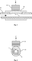
Der in
Die Aussparung
Durch die Aussparung
Um Eigenspannungen der Sensorkomponente
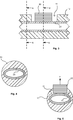
Der Querschnitt der Sensorkomponente
Eine gerade oder einer Geraden ähnliche Linie, welche die Geometrie der für die Messzwecke benötigte Membran bestimmt
Eine gerade oder gebogene Linie gegenüber der Membran, die eine Stützfunktion der Weichkomponente gegenüber der rohr- oder skelettförmigen Hartkomponente wahrnimmt.
Eine Geometrie zur Realisierung einer federnden Funktion an den beiden Seiten der Weichkomponente, damit eine Vorspannung aufgebaut werden kann, die zur Messung von Drücken unterhalb des atmosphärischen Umgebungsdrucks notwendig ist. Darüber hinaus ist die federnde Funktion notwendig, dass sich die Membran bei einem steigenden Innendruck von ihrer gegenüberliegenden Stützfläche entfernen kann.The cross section of the
A straight line or a straight line that determines the geometry of the membrane needed for the measurement purposes
A straight or curved line opposite the membrane, which performs a supporting function of the soft component against the tubular or skeletal hard component.
A geometry to provide a resilient function on both sides of the soft component to provide a preload necessary to measure pressures below atmospheric ambient pressure. In addition, the resilient function is necessary that the membrane can move away from its opposite support surface with increasing internal pressure.
Die Innenfläche des Stutzens
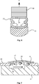
Die Hartkomponente, die den Stempel
Die Hauptströmung des Fluids ist dabei durch einen horizontalen Pfeil nach rechts dargestellt. Möglicherweise kann das Volumen unterhalb der Membran
Die von der Membran der Sensorkomponente
BezugszeichenlisteLIST OF REFERENCE NUMBERS
- 1010
- Stutzen, Einlassstutzen, Auslassstutzen Nozzle, inlet connection, outlet connection
- 1111
- Aussparung recess
- 2020
- Sensorkomponente, Membran Sensor component, membrane
- 21,2221.22
- Membranseite membrane side
- 2323
- Membranoberseite Membrane surface
- 3030
- Kraftsensor, Stempel Force sensor, stamp
- 4040
- Flansch flange
- 4141
- Ventilscheibe valve disc
- 4242
- Labyrinth labyrinth
- 4343
- Vertiefung deepening
ZITATE ENTHALTEN IN DER BESCHREIBUNG QUOTES INCLUDE IN THE DESCRIPTION
Diese Liste der vom Anmelder aufgeführten Dokumente wurde automatisiert erzeugt und ist ausschließlich zur besseren Information des Lesers aufgenommen. Die Liste ist nicht Bestandteil der deutschen Patent- bzw. Gebrauchsmusteranmeldung. Das DPMA übernimmt keinerlei Haftung für etwaige Fehler oder Auslassungen.This list of the documents listed by the applicant has been generated automatically and is included solely for the better information of the reader. The list is not part of the German patent or utility model application. The DPMA assumes no liability for any errors or omissions.
Zitierte PatentliteraturCited patent literature
- US 7887308 B2 [0002] US 7887308 B2 [0002]
- DE 3838689 C1 [0004] DE 3838689 C1 [0004]
- EP 0208955 A2 [0006] EP 0208955 A2 [0006]
- DE 4340536 A1 [0007] DE 4340536 A1 [0007]
- DE 3035703 A1 [0008] DE 3035703 A1 [0008]
Claims (12)
Priority Applications (8)
| Application Number | Priority Date | Filing Date | Title |
|---|---|---|---|
| DE102012102273A DE102012102273A1 (en) | 2012-03-19 | 2012-03-19 | Device for feeding and dosing a fluid for medical purposes |
| US14/384,543 US10300192B2 (en) | 2012-03-19 | 2012-11-06 | Device for supplying and metering a fluid for medicinal purposes |
| PCT/EP2012/071942 WO2013139408A1 (en) | 2012-03-19 | 2012-11-06 | Device for supplying and metering a fluid for medicinal purposes |
| EP12780766.7A EP2663773B1 (en) | 2012-03-19 | 2012-11-06 | Device for supplying and metering a fluid for medicinal purposes |
| JP2015500781A JP6185550B2 (en) | 2012-03-19 | 2012-11-06 | Device for supplying and measuring fluids for medical purposes |
| RU2014142055/06A RU2595297C2 (en) | 2012-03-19 | 2012-11-06 | Device for supplying and metering fluid for medicinal purposes |
| BR112014021577-4A BR112014021577B1 (en) | 2012-03-19 | 2012-11-06 | APPARATUS FOR THE SUPPLY AND MEASUREMENT OF A FLUID FOR MEDICAL PURPOSES |
| CN201280071566.2A CN104220751B (en) | 2012-03-19 | 2012-11-06 | For supply and the device of metering fluid for medical purpose |
Applications Claiming Priority (1)
| Application Number | Priority Date | Filing Date | Title |
|---|---|---|---|
| DE102012102273A DE102012102273A1 (en) | 2012-03-19 | 2012-03-19 | Device for feeding and dosing a fluid for medical purposes |
Publications (2)
| Publication Number | Publication Date |
|---|---|
| DE102012102273A1 true DE102012102273A1 (en) | 2013-09-19 |
| DE102012102273A8 DE102012102273A8 (en) | 2013-12-05 |
Family
ID=47116034
Family Applications (1)
| Application Number | Title | Priority Date | Filing Date |
|---|---|---|---|
| DE102012102273A Withdrawn DE102012102273A1 (en) | 2012-03-19 | 2012-03-19 | Device for feeding and dosing a fluid for medical purposes |
Country Status (8)
| Country | Link |
|---|---|
| US (1) | US10300192B2 (en) |
| EP (1) | EP2663773B1 (en) |
| JP (1) | JP6185550B2 (en) |
| CN (1) | CN104220751B (en) |
| BR (1) | BR112014021577B1 (en) |
| DE (1) | DE102012102273A1 (en) |
| RU (1) | RU2595297C2 (en) |
| WO (1) | WO2013139408A1 (en) |
Families Citing this family (7)
| Publication number | Priority date | Publication date | Assignee | Title |
|---|---|---|---|---|
| US20200268966A1 (en) * | 2015-11-16 | 2020-08-27 | Onefusion Ag | Procedure to operate a perfusion device and perfusion device to implement the procedure |
| KR101833899B1 (en) * | 2016-02-18 | 2018-03-05 | (주)선메딕스 | Blood access apparatus with pressor sensor and drug filter |
| CN106267454B (en) * | 2016-08-29 | 2019-08-06 | 上海交通大学 | A kind of infusion pump warning device and a kind of infusion pump alarm method |
| RU2626193C1 (en) * | 2016-11-24 | 2017-07-24 | федеральное государственное бюджетное образовательное учреждение высшего образования "Санкт-Петербургский горный университет" | Flexible-hose mixing pump for pasty substances |
| JP6570778B1 (en) * | 2019-02-28 | 2019-09-04 | 株式会社イワキ | Tube diaphragm pump |
| CN110057421A (en) * | 2019-05-15 | 2019-07-26 | 山东省计量科学研究院 | A kind of full-automatic device and method for surveying oily volume of sample automatic measurement |
| CN112113025B (en) * | 2020-09-10 | 2022-11-15 | 广东博智林机器人有限公司 | Pipeline pressure valve and slurry conveying device |
Citations (9)
| Publication number | Priority date | Publication date | Assignee | Title |
|---|---|---|---|---|
| DE3035703A1 (en) | 1980-09-22 | 1982-05-06 | Siemens AG, 1000 Berlin und 8000 München | Infusion appliance monitor - responds to irregular pressure rise upstream of catheter |
| EP0208955A2 (en) | 1985-07-17 | 1987-01-21 | Peter von Berg, Extrakorporale Systeme -Medizintechnik GmbH | Process for producing a pressure-transmitting contact between the membrane of a pressure dome and the pressure transmitter of a measuring transducer, and pressure measuring device for determining the physiological pressure of fluids of human or animal bodies |
| DE3838689C1 (en) | 1988-11-15 | 1990-06-28 | Fresenius Ag, 6380 Bad Homburg, De | Method for the continuous measurement of the pressure in a flexible fluid line for medical purposes, as well as a device for carrying out the method |
| DE4340536A1 (en) | 1993-10-29 | 1995-05-04 | Lang Volker | Device for monitoring intravenous infusion therapy with particular suitability for use of infusion pumps and administration of small infusion amounts in paediatrics |
| US6171253B1 (en) * | 1999-05-04 | 2001-01-09 | Apex Medical, Inc. | Flat tube pressure sensor |
| DE10305036A1 (en) * | 2003-02-07 | 2004-08-26 | Richard Wolf Gmbh | Medical pump pressure sensor has two pressure measurement elements on single circuit board in membrane coupled housing |
| DE102005052927A1 (en) * | 2005-11-03 | 2007-05-10 | Pvb Critical Care Gmbh | Infusion and blood pressure measuring instrument for patients has pressure measuring sensor, valve and exhaust port, which is connected with hose that can be locked by means of hose clip |
| US7887308B2 (en) | 2004-11-29 | 2011-02-15 | Swissinnov Product Sarl | Volumetric pump with reciprocated and rotated piston |
| EP2359932A1 (en) * | 2010-01-22 | 2011-08-24 | Tecan Trading AG | Positive displacement pump with pressure sensor |
Family Cites Families (18)
| Publication number | Priority date | Publication date | Assignee | Title |
|---|---|---|---|---|
| US2274479A (en) * | 1939-07-22 | 1942-02-24 | Bristol Company | Device for measuring fluid pressures |
| US3178942A (en) * | 1962-02-16 | 1965-04-20 | Penn Meter Company | Primary metering devices |
| US3802265A (en) * | 1972-09-07 | 1974-04-09 | Allied Chem | Apparatus for use in measuring the flow velocity of fluid within a conduit |
| US4218926A (en) * | 1979-01-25 | 1980-08-26 | Dover Corporation | Isolating pressure sensor |
| DE3209721A1 (en) * | 1982-03-17 | 1983-09-29 | MGVG Medizinische Geräte Vertriebs-Gesellschaft mbH, 8000 München | Infusion device |
| JP3006199B2 (en) | 1991-09-03 | 2000-02-07 | 株式会社日立製作所 | Optical disc manufacturing method |
| JPH0725949Y2 (en) * | 1992-01-30 | 1995-06-14 | 日本光電工業株式会社 | Infusion set |
| US5410916A (en) * | 1994-06-24 | 1995-05-02 | Honeywell Inc. | Flowthrough pressure sensor |
| US5514102A (en) * | 1995-05-05 | 1996-05-07 | Zevex Incorporated | Pressure monitoring enteral feeding system and method |
| IL120651A (en) | 1997-04-11 | 2001-06-14 | Nestle Sa | Administration of liquid to a patient |
| US6755079B1 (en) * | 2000-03-27 | 2004-06-29 | Halliburton Energy Services, Inc. | Method and apparatus for determining fluid viscosity |
| US6523414B1 (en) * | 2001-04-16 | 2003-02-25 | Zevex, Inc. | Optical pressure monitoring system |
| JP3915474B2 (en) | 2001-11-02 | 2007-05-16 | 株式会社ジェイ・エム・エス | Pressure detector |
| AUPR982302A0 (en) * | 2002-01-03 | 2002-01-31 | Pax Fluid Systems Inc. | A fluid flow controller |
| DE20317579U1 (en) | 2003-11-14 | 2004-01-15 | Wenning, Franz | Continuously safe piston pump |
| US20090112155A1 (en) * | 2007-10-30 | 2009-04-30 | Lifescan, Inc. | Micro Diaphragm Pump |
| WO2010031424A1 (en) | 2008-09-22 | 2010-03-25 | Fraunhofer-Gesellschaft zur Förderung der angewandten Forschung e.V. | Device for determining at least one flow parameter |
| DE102012102274B4 (en) * | 2012-03-19 | 2018-05-24 | B. Braun Melsungen Ag | piston pump |
-
2012
- 2012-03-19 DE DE102012102273A patent/DE102012102273A1/en not_active Withdrawn
- 2012-11-06 JP JP2015500781A patent/JP6185550B2/en active Active
- 2012-11-06 EP EP12780766.7A patent/EP2663773B1/en active Active
- 2012-11-06 RU RU2014142055/06A patent/RU2595297C2/en active
- 2012-11-06 WO PCT/EP2012/071942 patent/WO2013139408A1/en active Application Filing
- 2012-11-06 BR BR112014021577-4A patent/BR112014021577B1/en active IP Right Grant
- 2012-11-06 CN CN201280071566.2A patent/CN104220751B/en active Active
- 2012-11-06 US US14/384,543 patent/US10300192B2/en active Active
Patent Citations (9)
| Publication number | Priority date | Publication date | Assignee | Title |
|---|---|---|---|---|
| DE3035703A1 (en) | 1980-09-22 | 1982-05-06 | Siemens AG, 1000 Berlin und 8000 München | Infusion appliance monitor - responds to irregular pressure rise upstream of catheter |
| EP0208955A2 (en) | 1985-07-17 | 1987-01-21 | Peter von Berg, Extrakorporale Systeme -Medizintechnik GmbH | Process for producing a pressure-transmitting contact between the membrane of a pressure dome and the pressure transmitter of a measuring transducer, and pressure measuring device for determining the physiological pressure of fluids of human or animal bodies |
| DE3838689C1 (en) | 1988-11-15 | 1990-06-28 | Fresenius Ag, 6380 Bad Homburg, De | Method for the continuous measurement of the pressure in a flexible fluid line for medical purposes, as well as a device for carrying out the method |
| DE4340536A1 (en) | 1993-10-29 | 1995-05-04 | Lang Volker | Device for monitoring intravenous infusion therapy with particular suitability for use of infusion pumps and administration of small infusion amounts in paediatrics |
| US6171253B1 (en) * | 1999-05-04 | 2001-01-09 | Apex Medical, Inc. | Flat tube pressure sensor |
| DE10305036A1 (en) * | 2003-02-07 | 2004-08-26 | Richard Wolf Gmbh | Medical pump pressure sensor has two pressure measurement elements on single circuit board in membrane coupled housing |
| US7887308B2 (en) | 2004-11-29 | 2011-02-15 | Swissinnov Product Sarl | Volumetric pump with reciprocated and rotated piston |
| DE102005052927A1 (en) * | 2005-11-03 | 2007-05-10 | Pvb Critical Care Gmbh | Infusion and blood pressure measuring instrument for patients has pressure measuring sensor, valve and exhaust port, which is connected with hose that can be locked by means of hose clip |
| EP2359932A1 (en) * | 2010-01-22 | 2011-08-24 | Tecan Trading AG | Positive displacement pump with pressure sensor |
Also Published As
| Publication number | Publication date |
|---|---|
| EP2663773B1 (en) | 2017-01-11 |
| CN104220751A (en) | 2014-12-17 |
| US10300192B2 (en) | 2019-05-28 |
| EP2663773A1 (en) | 2013-11-20 |
| BR112014021577B1 (en) | 2021-06-22 |
| RU2595297C2 (en) | 2016-08-27 |
| JP6185550B2 (en) | 2017-08-23 |
| RU2014142055A (en) | 2016-05-20 |
| DE102012102273A8 (en) | 2013-12-05 |
| WO2013139408A1 (en) | 2013-09-26 |
| CN104220751B (en) | 2016-09-07 |
| JP2015515299A (en) | 2015-05-28 |
| US20150032055A1 (en) | 2015-01-29 |
Similar Documents
| Publication | Publication Date | Title |
|---|---|---|
| EP2663773B1 (en) | Device for supplying and metering a fluid for medicinal purposes | |
| DE102012102274B4 (en) | piston pump | |
| EP2665934B1 (en) | Piston pump; device for feeding and metering a fluid for medical purposes by means of a piston pump | |
| DE19856744C2 (en) | Pump hose system for peristaltic delivery of liquid or gaseous media | |
| EP0337092A3 (en) | Flowmeter for fluids | |
| EP3452135B1 (en) | Medical treatment device and hose set for a medical treatment device | |
| DE3428828A1 (en) | DEVICE FOR CONVEYING MECHANICAL STRESS HIGH-SENSITIVE LIQUIDS | |
| DE2826033A1 (en) | INFUSION PUMP | |
| EP3381489B1 (en) | Medical pumping device | |
| DE102013103223A1 (en) | Peristaltic pump with crushing force changing device and method for changing a squeezing pressure in an infusion tube of a peristaltic pump | |
| WO2019101640A1 (en) | Sensor arrangement for detecting a flow of fluid | |
| EP2607875A1 (en) | Pressure sensor through which a fluid flows and fluid delivery device with same | |
| EP2124031B1 (en) | Device for measuring pressure | |
| EP3593835A1 (en) | Infusion assembly for administering a medical fluid | |
| EP3628345B1 (en) | Kit for modular assembly of a medical pumping device and medical pumping device | |
| DE102013111799A1 (en) | Precision metering device for conveying a fluid | |
| DE3035703A1 (en) | Infusion appliance monitor - responds to irregular pressure rise upstream of catheter | |
| DE102020117216A1 (en) | Method and device for dosing solutions | |
| WO2020245267A1 (en) | Pressure-measuring assembly for an extracorporeal blood treatment machine | |
| DE102020132911A1 (en) | Anti-perforation protection for magnetic membrane coupling | |
| DE102009049431A1 (en) | Ophthalmosurgical pressure measuring device | |
| DE4328267A1 (en) | Diaphragm pump | |
| DE8207937U1 (en) | DIAPHRAGM DISPLACEMENT PUMP |
Legal Events
| Date | Code | Title | Description |
|---|---|---|---|
| R163 | Identified publications notified | ||
| R082 | Change of representative |
Representative=s name: WINTER, BRANDL - PARTNERSCHAFT MBB, PATENTANWA, DE Representative=s name: WINTER, BRANDL, FUERNISS, HUEBNER, ROESS, KAIS, DE |
|
| R119 | Application deemed withdrawn, or ip right lapsed, due to non-payment of renewal fee |