HINTERGRUND DER ERFINDUNG BACKGROUND OF THE INVENTION
1. Bereich der Erfindung 1. Field of the invention
Diese Erfindung betrifft eine Steuervorrichtung für ein Fahrzeugantriebssystem mit einem elektrischen Differenzialabschnitt nach dem Oberbegriff von Anspruch 1, der einen Differenzialmechanismus aufweist, der zum Durchführen einer Differenzialwirkung wirksam ist, und einem Getriebeabschnitt, der in einem Leistungsübertragungspfad zwischen dem Differenzialabschnitt und Antriebsrädern angeordnet ist, und insbesondere auf eine Technologie zum Steuern eines Schaltvorgangs bei dem Getriebeabschnitt als Reaktion auf eine Schaltanforderung für das Schalten. This invention relates to a control apparatus for a vehicular drive system having an electric differential portion according to the preamble of claim 1 having a differential mechanism effective to perform a differential action and a transmission portion disposed in a power transmission path between the differential portion and drive wheels, and more particularly to a technology for controlling a shift operation at the transmission portion in response to a shift request for shifting.
2. Beschreibung des zugehörigen Stands der Technik 2. Description of the Related Art
Eine Steuervorrichtung für ein Fahrzeugantriebssystem ist bisher bekannt, wobei diese einen Differenzialabschnitt, der einen Differenzialmechanismus hat, der zum Verteilen einer Verbrennungsmotorabgabe auf einen ersten Elektromotor und ein Leistungsübertragungselement wirksam ist, und einen Getriebeabschnitt, insbesondere einen Schaltabschnitt hat, der in einem Leistungsübertragungspfad zwischen dem Differenzialabschnitt und Antriebsrädern angeordnet ist. Der Differenzialabschnitt weist ein erstes Element, das mit dem Verbrennungsmotor verbunden ist, ein zweites Element, das mit dem ersten Element und dem ersten Elektromotor verbunden ist, und ein drittes Element auf, das mit dem Leistungsübertragungselement verbunden ist. Mit einem solchen Aufbau hat der Differenzialabschnitt eine Differenzialwirkung, mit der ein Drehzahlverhältnis stufenlos variiert wird, so dass dieser als stufenlos variables Getriebe funktioniert. A control apparatus for a vehicle drive system has heretofore been known, having a differential portion having a differential mechanism effective for distributing an engine output to a first electric motor and a power transmitting member, and a transmission portion, particularly a switching portion, in a power transmission path between the differential portion and drive wheels is arranged. The differential portion includes a first member connected to the internal combustion engine, a second member connected to the first member and the first electric motor, and a third member connected to the power transmitting member. With such a structure, the differential portion has a differential action with which a speed ratio is varied steplessly, so that it functions as a continuously variable transmission.
Unterdessen offenbart eine Patentoffenlegungsschrift ( Japanische Patentanmeldungsoffenlegungsschrift Nr. 9-37410 ) eine Technologie, die sich auf eine Fahrzeugantriebssteuervorrichtung bezieht, die ein stufenlos variables Getriebe hat, das ein Drehzahlverhältnis des stufenlos variablen Getriebes mit einer Variation einer Fahrzeuggeschwindigkeit variiert. Dadurch kann eine Verbrennungsmotordrehzahl ungeachtet der Variation der Fahrzeuggeschwindigkeit auf einem feststehenden Niveau aufrechterhalten werden, kann anders gesagt nämlich ungeachtet einer Variation einer Ausgangsdrehzahl des stufenlos variablen Getriebes auf einem feststehenden Niveau aufrecht erhalten werden. Zusätzlich sind andere Technologien bekannt, die in dem Japanischen Patent Nr. 3526955 und der Japanischen Patentanmeldungsoffenlegungsschrift Nr. 2002-243031 offenbart sind. Meanwhile, a patent publication ( Japanese Patent Application Publication No. 9-37410 A technology related to a vehicle drive control apparatus having a continuously variable transmission that varies a speed ratio of the continuously variable transmission with a variation of a vehicle speed. Thereby, an engine rotation speed can be maintained at a fixed level regardless of the variation of the vehicle speed, that is, regardless of a variation of an output speed of the continuously variable transmission, can be maintained at a fixed level. In addition, other technologies are known in the Japanese Patent No. 3526955 and the Japanese Patent Application Laid-Open Publication No. 2002-243031 are disclosed.
Auch mit einer Steuervorrichtung für ein Fahrzeugantriebssystem, das einen Differenzialabschnitt und einen Getriebeabschnitt hat, wird das Schalten bei dem Differenzialabschnitt gemäß dem Schalten bei dem Getriebeabschnitt im Hinblick darauf eingeleitet, dass der Verbrennungsmotor in einem Betriebsbereich mit einem hohen Wirkungsgrad betriebsfähig gehalten wird. Dadurch ist es möglich, die Verbrennungsmotordrehzahl auf einem nahezu feststehenden Niveau in einem Stadium vor und nach dem Schalten ungeachtet einer Variation einer Ausgangsdrehzahl des Differenzialabschnitts aufgrund des Schaltens bei dem Getriebeabschnitt aufrecht zu erhalten. Also, with a vehicle drive system control apparatus having a differential portion and a transmission portion, the shifting is initiated at the differential portion in accordance with the shifting at the transmission portion in view of keeping the engine operable in a high efficiency operating range. Thereby, it is possible to maintain the engine speed at a nearly fixed level at a stage before and after the shift regardless of a variation of an output speed of the differential portion due to the shift in the transmission portion.
Jedoch ergibt sich während des Betriebs der Steuervorrichtung für das Fahrzeugantriebssystem mit einem solchen Aufbau, der vorstehend erwähnt ist, bei dem Schalten eine Problematik. In Abhängigkeit von der Beziehung zwischen der Ausgangsdrehzahl des Getriebeabschnitts und der Verbrennungsmotordrehzahl dreht sich nämlich der erste Elektromotor (das zweite Element) mit einer Drehzahl, die auf der Grundlage der Beziehung von wechselseitigen relativen Drehzahlen des ersten bis dritten Elements des Differenzialabschnitts bestimmt wird, was eine hohe Drehzahl mit einer sich ergebenden Verringerung der Haltbarkeit dieser Bauteile zur Folge hat. Außerdem haben Ritzel, die den Differenzialmechanismus ausbilden, Drehzahlen (in anderer Hinsicht eine Differenz zwischen beispielsweise einer Drehzahl des Verbrennungsmotors (des ersten Elements) und einer Drehzahl des Leistungsübertragungselements (dritten Elements)), die in einen Bereich hoher Drehzahl mit einer sich ergebenden Verringerung der Haltbarkeit der Ritzel fallen (beispielsweise der Ritzelnadellager und -buchsen usw.). In Abhängigkeit von einer Schaltanforderung für den Automatikgetriebeabschnitt, insbesondere eines Drehzahlverhältnisses, das für den Getriebeabschnitt erforderlich ist, ist es wahrscheinlich, dass der erste Elektromotor sich mit einer hohen Drehzahl dreht, und wird verursacht, dass die Ritzel sich mit der hohen Drehzahl drehen. Bisher wurden keine Forschung und kein Studium im Stand der Technik im Hinblick auf das Auftreten einer Überdrehzahlrotation dieser Bauteile durchgeführt, und diese Problematik ist der Öffentlichkeit unbekannt geblieben. However, during the operation of the control apparatus for the vehicle drive system having such a construction mentioned above, there arises a problem in the shifting. Namely, depending on the relationship between the output speed of the transmission portion and the engine speed, the first electric motor (the second member) rotates at a rotational speed determined based on the relationship of mutual relative rotational speeds of the first to third elements of the differential portion high speed with a resulting reduction in the durability of these components result. In addition, sprockets constituting the differential mechanism have rotational speeds (in other respects a difference between, for example, a rotational speed of the internal combustion engine (the first element) and a rotational speed of the power transmitting element (third element)), which are in a high-speed region with a consequent reduction in the Durability of the pinions fall (for example, the pinion bearings and bushings, etc.). In response to a shift request for the automatic transmission portion, particularly a speed ratio required for the transmission portion, the first electric motor is likely to rotate at a high speed and causes the pinions to rotate at the high speed. So far, no research or study has been made in the prior art with regard to the occurrence of overspeed rotation of these components, and this problem has remained unknown to the public.
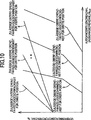
12 ist ein gut bekanntes Liniendiagramm, das Drehzahlen der jeweiligen Drehelemente darstellt, die den Differenzialabschnitt ausbilden. Das Liniendiagramm zeigt Beispiele einer Variation von Drehzahlen der jeweiligen Drehelemente, wenn ein Hochschalten bei dem Getriebeabschnitt ausgeführt wird, gemeinsam mit der Beziehung, die mit der Ausgangsdrehzahl des Getriebeabschnitts verknüpft ist. In 12 stellt die Referenz „ENG“ die Drehzahl des ersten Drehelements (des ersten Elements) dar, das mit dem Verbrennungsmotor verbunden ist; stellt „M1“ die Drehzahl des zweiten Drehelements (des zweiten Elements) dar, das mit dem ersten Elektromotor verbunden ist; stellt „M2“ die Drehzahl des dritten Drehelements (des dritten Elements) dar, das mit dem Leistungsübertragungselement und dem zweiten Elektromotor verbunden ist; und stellt „AUSGANG“ die Ausgangsdrehzahl des Getriebeabschnitts dar. Zusätzlich stellen jeweilige Geraden, die sich auf den Differenzialabschnitt beziehen, Relativbewegungsbeziehungen der Drehzahl zwischen den jeweiligen Drehelementen dar. Durchgezogene Linien deuten die Relativbewegungsbeziehungen vor der Ausführung eines Hochschaltvorgangs an und gestrichelte Linien deuten die Relativbewegungsbeziehungen nachfolgend auf den Hochschaltvorgang an. 12 is a well-known line graph that represents speeds of rotation of the respective rotary elements forming the differential section. The line graph shows examples of variation of rotational speeds of the respective rotary elements when upshifting is performed on the transmission section, along with the relationship associated with the output speed of the transmission section. In 12 The reference "ENG" represents the rotational speed of the first rotary element (the first element) connected to the internal combustion engine is; "M1" represents the rotational speed of the second rotary member (the second member) connected to the first electric motor; "M2" represents the rotational speed of the third rotating element (the third element) connected to the power transmitting member and the second electric motor; In addition, respective straight lines related to the differential portion represent relative motion relationships of the rotational speed between the respective rotary members. Solid lines indicate the relative movement relationships before performing an upshift operation, and dashed lines indicate the relative movement relationships below on the upshift.
Wenn das Hochschalten mit einer Verringerung der Drehzahl „M2“ ausgeführt wird, wie in 12 gezeigt ist, wird die Drehzahl „M1“ des zweiten Elements angehoben, so dass diese die Drehzahl „ENG“ des ersten Elements auf einem nahezu feststehenden Niveau aufrechterhält. Während eines derartigen Hochschaltens war es dann, wenn die Ausgangsdrehzahl des Getriebeabschnitts in einem relativ niedrigen Zustand verbleibt, wenn die Verbrennungsmotordrehzahl in einem relativ hohen Zustand verbleibt, wahrscheinlich, dass das erste Element eine sich erhöhende Drehzahl hat, so dass der erste Elektromotor sich bei einer hohen Drehzahl dreht. Außerdem ergibt das eine relativ betrachtet erhöhte Differenz der Drehzahl zwischen der Verbrennungsmotordrehzahl und dem Leistungsübertragungselement (dem zweiten Elektromotor), was verursacht, dass sich die Wahrscheinlichkeit ergibt, dass die Ritzel, die den Differenzialabschnitt ausbilden, sich bei hohen Drehzahlen drehen. When the upshift is performed with a reduction in the speed "M2" as in 12 is shown, the rotational speed "M1" of the second element is raised so that it maintains the rotational speed "ENG" of the first element at a nearly fixed level. During such an upshift, when the output speed of the transmission portion remains in a relatively low state, when the engine speed remains in a relatively high state, it is likely that the first element has an increasing speed, so that the first electric motor at a high speed turns. In addition, this results in a relatively increased difference in rotational speed between the engine speed and the power transmitting member (the second electric motor), which causes the likelihood that the pinions forming the differential portion to rotate at high rotational speeds.
Obwohl das vorstehend Angegebene unter Bezugnahme auf den Hochschaltvorgang des Getriebeabschnitts beschrieben wurde, ist offensichtlich, dass die Ritzel sich wahrscheinlich bei der hohen Drehzahl drehen, wenn ein Herunterschaltvorgang bei dem Getriebeabschnitt bewirkt wird. In diesem Fall liegt die Drehzahl des ersten Elektromotors lediglich in einer negativen Phase und bestand in ähnlicher Weise die Wahrscheinlichkeit, dass verursacht wird, dass der erste Elektromotor sich bei einer hohen Drehzahl dreht. Zusätzlich wurde das vorstehend Angegebene beispielhaft unter Bezugnahme auf ein Schalten beschrieben, das durch die Steuervorrichtung des Fahrzeugantriebssystems eingeleitet wird, bei dem eine Schaltsteuerung durchgeführt wird, um die Verbrennungsmotordrehzahl auf dem nahezu feststehenden Niveau zu halten, nämlich gemäß dem Schalten bei dem Getriebeabschnitt in einem Stadium vor und nach dem Schalten. Jedoch sind die beschriebenen spezifischen Anordnungen nur als Darstellung gedacht und ist die vorliegende Problematik nicht auf eine solche Schaltsteuerung beschränkt. Es ist natürlich klar, dass sich die vorliegende Problematik auch dann ergibt, wenn beispielsweise die Verbrennungsmotordrehzahl in einem Stadium vor und nach dem Schaltvorgang variiert wird. Although the above is described with reference to the upshifting operation of the transmission portion, it is apparent that the sprockets are likely to rotate at the high speed when a downshift operation is effected on the transmission portion. In this case, the rotational speed of the first electric motor is only in a negative phase, and similarly, the likelihood of causing the first electric motor to rotate at a high rotational speed. In addition, the above has been described by way of example with reference to a shift initiated by the control apparatus of the vehicle drive system in which a shift control is performed to keep the engine speed at the almost fixed level, namely, in one stage at the transmission portion before and after switching. However, the described specific arrangements are intended to be illustrative only, and the present problem is not limited to such switching control. It is of course clear that the present problem arises even if, for example, the engine speed is varied in one stage before and after the switching operation.
Im Stand der Technik nach DE 603 05 549 T2 ist eine Steuervorrichtung für ein Fahrzeugantriebssystem mit den Merkmalen des Oberbegriffs von Anspruch 1 dargestellt. Bei dem Aufbau in diesem Stand der Technik wird bei einer Wärmeentwicklung an dem Motor-Generator die Solldrehzahl der Primärantriebseinrichtung geändert. According to the state of the art DE 603 05 549 T2 a control device for a vehicle drive system having the features of the preamble of claim 1 is shown. In the structure in this prior art, the target rotational speed of the primary drive device is changed in a heat generation at the motor-generator.
Ergänzend zeigt der Stand der Technik nach DE 10 2005 010 883 A2 eine Steuervorrichtung für ein Fahrzeugantriebssystem mit einer unterstützenden Leistungsquelle, die mit dem Ausgangselement einer Hauptleistungsquelle indirekt über ein Getriebe verbunden ist. In addition, the prior art shows DE 10 2005 010 883 A2 a control system for a vehicle drive system having a supporting power source connected to the output element of a main power source indirectly via a transmission.
ZUSAMMENFASSUNG DER ERFINDUNG SUMMARY OF THE INVENTION
Die vorliegende Erfindung wurde mit Blick auf das vorstehend Angegebene gemacht und hat die Aufgabe, eine Steuervorrichtung für ein Fahrzeugantriebssystem zu schaffen, die wirksam ist, um ein Schalten bei einem Getriebeabschnitt geeignet zu steuern, um zu unterdrücken, dass eines von Drehelementen eines Differenzialabschnitts sich bei einer hohen Drehzahl bei Anwesenheit einer Schaltanforderung für den Getriebeabschnitt dreht. The present invention has been made in view of the above, and has an object to provide a control apparatus for a vehicle drive system, which is operative to properly control a shift in a transmission portion to suppress that one of rotary elements of a differential portion at a high speed in the presence of a switching request for the transmission section rotates.
Die Aufgabe wird erfindungsgemäß mit einer Steuervorrichtung nach Anspruch 1 gelöst. Weitere vorteilhafte Weiterbildungen der Erfindung sind in den abhängigen Ansprüchen definiert. The object is achieved with a control device according to claim 1. Further advantageous developments of the invention are defined in the dependent claims.
Zum Lösen einer solchen Aufgabe ist die in Anspruch 1 genannte Erfindung durch eine Steuervorrichtung für ein Fahrzeugantriebssystem mit einem Differenzialabschnitt, der einen Differenzialmechanismus aufweist, der ein erstes Drehelement, das mit einem Verbrennungsmotor verbunden ist, ein zweites Drehelement, das mit einem ersten Elektromotor verbunden ist, und ein drittes Drehelement hat, das mit einem Leistungsübertragungselement zum Verteilen einer Abgabe des Verbrennungsmotors auf den ersten Elektromotor und das Leistungsübertragungselement verbunden ist, und einen Getriebeabschnitt definiert, der in einem Leistungsübertragungspfad zwischen dem Leistungsübertragungselement und Antriebsrädern angeordnet ist, wobei die Steuervorrichtung gekennzeichnet ist durch eine Getriebeabschnittsschaltbegrenzungseinrichtung, die unter Bestimmung eines zulässigen Bereichs eines Drehzahlverhältnisses des Getriebeabschnitts für eine Schaltanforderung für den Getriebeabschnitt unter Berücksichtigung einer Drehzahl eines der Drehelemente des Differenzialabschnitts ein Schalten des Getriebeabschnitts auf der Grundlage des zulässigen Bereichs begrenzt. To solve such a problem, the invention recited in claim 1 by a vehicle drive system control device having a differential portion having a differential mechanism, a first rotary element connected to an internal combustion engine, a second rotary element connected to a first electric motor and a third rotary member connected to a power transmitting member for distributing a discharge of the internal combustion engine to the first electric motor and the power transmitting member, and a transmission portion disposed in a power transmission path between the power transmitting member and drive wheels, the control apparatus being characterized by a gear portion shift limiting means which, while determining an allowable range of a speed ratio of the transmission portion for a shift request for the transmission portion under Berc In view of a rotational speed of one of the rotary elements of the differential section, a switching of the gear section is limited on the basis of the permissible range.
Mit einem solchen Aufbau bestimmt die Getriebeabschnittsschaltbegrenzungseinrichtung den zulässigen Bereich des Drehzahlverhältnisses bei dem Schalten, das für den Getriebeabschnitt angefordert wird, als Drehzahlverhältnis für den Getriebeabschnitt unter Berücksichtigung der Drehzahl eines der Drehelemente des Differenzialabschnitts, um dadurch das Schalten in dem Getriebeabschnitt zu begrenzen. Wenn daher die Schaltanforderung des Getriebeabschnitts vorhanden ist, kann vermieden werden, dass eines der Drehelemente des Differenzialabschnitts sich bei der hohen Drehzahl dreht. Das ergibt als Folge die Unterdrückung der hohen Drehzahlen von beispielsweise dem ersten Elektromotor und den Ritzeln, die das Differenzialgetriebe ausbilden, mit dem Ergebnis von Verbesserungen der Haltbarkeit des ersten Elektromotors und der Ritzel. With such a structure, the transmission portion shift limiting means determines the allowable range of the speed ratio in the shift requested for the transmission portion as the speed ratio for the transmission portion taking into consideration the rotational speed of one of the rotary members of the differential portion to thereby limit the shifting in the transmission portion. Therefore, when the shift request of the transmission portion is present, it can be avoided that any one of the rotating elements of the differential portion rotates at the high speed. As a result, this results in the suppression of the high rotational speeds of, for example, the first electric motor and the pinions forming the differential gear, with the result of improvements in the durability of the first electric motor and the pinions.
Die in Anspruch 2 angegebene Erfindung ist mit Anspruch 1 dadurch definiert, dass die Getriebeabschnittsschaltbegrenzungseinrichtung den zulässigen Bereich bestimmt, um zu verhindern, dass eine Drehzahl eines der Drehelemente hoch ist, durch Bezugnahme auf eine Beziehung zwischen einem für eine Ausgangsdrehzahl relevanten Wert des Getriebeabschnitts und einer Verbrennungsmotordrehzahl. Mit einem solchen Aufbau begrenzt die Getriebeabschnittsschaltbegrenzungseinrichtung geeignet das Schalten bei dem Getriebeabschnitt. The invention recited in claim 2 is defined by claim 1, wherein the gear portion shift limiting means determines the allowable range for preventing a rotational speed of one of the rotary members from being high by referring to a relationship between a value of the gear portion relevant to an output rotational speed engine speed. With such a structure, the transmission portion shift limiting device appropriately limits the shifting in the transmission portion.
Die in Anspruch 3 angegebene Erfindung ist mit Anspruch 1 oder 2 dadurch definiert, dass die Getriebeabschnittsschaltbegrenzungseinrichtung den zulässigen Bereich bestimmt, um zu verhindern, dass eine relative Drehzahl zwischen Drehelementen hoch ist, durch Bezugnahme auf eine Beziehung zwischen einem für eine Ausgangsdrehzahl relevanten Wert des Getriebeabschnitts und einer Verbrennungsmotordrehzahl. Mit einem solchen Aufbau begrenzt die Getriebeabschnittsschaltbegrenzungseinrichtung geeignet das Schalten bei dem Getriebeabschnitt. The invention recited in claim 3 is defined by claim 1 or 2 in that the transmission portion shift limiting means determines the allowable range for preventing a relative rotational speed between rotary members from being high by referring to a relationship between a value of the transmission portion relevant to an output rotational speed and an engine speed. With such a structure, the transmission portion shift limiting device appropriately limits the shifting in the transmission portion.
Die in Anspruch 4 angegebene Erfindung ist mit einem der Ansprüche 1 bis 3 definiert, wobei sie ferner einen zweiten Elektromotor aufweist, der mit dem Leistungsübertragungselement verbunden ist, wobei die Getriebeabschnittsschaltbegrenzungseinrichtung den zulässigen Bereich bestimmt, um eine hohe Drehzahl einer relativen Drehzahl zwischen einem Drehelement, das mit dem zweiten Elektromotor verbunden ist, und einem Drehelement, das in Eingriff mit dem verbundenen Drehelement steht, zu verhindern. Mit einem solchen Aufbau begrenzt die Getriebeabschnittsschaltbegrenzungseinrichtung geeignet das Schalten bei dem Getriebeabschnitt. The invention set forth in claim 4 is defined by claim 1, further comprising a second electric motor connected to the power transmitting member, wherein the gear portion switching limiting means determines the allowable range to obtain a high rotational speed of a relative rotational speed between a rotary member, which is connected to the second electric motor, and a rotary member, which is in engagement with the connected rotary member to prevent. With such a structure, the transmission portion shift limiting device appropriately limits the shifting in the transmission portion.
Die in Anspruch 5 angegebene Erfindung ist mit einem der Ansprüche 1 bis 4 dadurch definiert, dass die Getriebeabschnittsschaltbegrenzungseinrichtung das Schalten des Getriebeabschnitts durch Unterbinden des für den Getriebeabschnitt angeforderten Schaltens begrenzt. Mit einem solchen Aufbau kann beim Aufnehmen der Schaltanforderung für den Getriebeabschnitt geeignet vermieden werden, dass eines der Drehelemente des Differenzialabschnitts sich mit einer hohen Drehzahl dreht. The invention defined in claim 5 is defined by one of claims 1 to 4, characterized in that the transmission portion shift limiting means limits the switching of the transmission portion by inhibiting the requested for the transmission portion switching. With such a structure, when receiving the shift request for the transmission portion, it can be suitably avoided that one of the rotary members of the differential portion rotates at a high speed.
Die in Anspruch 6 angegebene Erfindung ist mit einem der Ansprüche 1 bis 4 dadurch definiert, dass die Getriebeabschnittsschaltbegrenzungseinrichtung das Schalten des Getriebeabschnitts durch Verzögern des für den Getriebeabschnitt angeforderten Schaltens begrenzt. Mit einem solchen Aufbau kann beim Aufnehmen der Schaltanforderung für den Getriebeabschnitt geeignet vermieden werden, dass eines der Drehelemente des Differenzialabschnitts sich mit einer hohen Drehzahl dreht. The invention recited in claim 6 is defined by one of claims 1 to 4 in that the transmission portion shift limiting means limits the shifting of the transmission portion by delaying the shift requested for the transmission portion. With such a structure, when receiving the shift request for the transmission portion, it can be suitably avoided that one of the rotary members of the differential portion rotates at a high speed.
Die in Anspruch 7 angegebene Erfindung ist mit einem der Ansprüche 1 bis 4 dadurch definiert, dass die Getriebeabschnittsschaltbegrenzungseinrichtung das Schalten des Getriebeabschnitts durch Bewirken eines Schaltens begrenzt, das von dem Schalten verschieden ist, das für den Getriebeabschnitt angefordert wird. Mit einem solchen Aufbau kann beim Aufnehmen der Schaltanforderung für den Getriebeabschnitt geeignet vermieden werden, dass eines der Drehelemente des Differenzialabschnitts sich mit einer hohen Drehzahl dreht. The invention recited in claim 7 is defined by one of claims 1 to 4 in that the transmission portion shift limiting means limits the shifting of the transmission portion by effecting a shift different from the shift requested for the transmission portion. With such a structure, when receiving the shift request for the transmission portion, it can be suitably avoided that one of the rotary members of the differential portion rotates at a high speed.
Die in Anspruch 8 angegebene Erfindung ist mit einem der Ansprüche 1 bis 4 dadurch definiert, dass die Getriebeabschnittsschaltbegrenzungseinrichtung das Schalten des Getriebeabschnitts durch erzwungenes Bewirken eines Schaltens von einem gegenwärtigen Zustand des Getriebeabschnitts begrenzt. Mit einem solchen Aufbau kann beim Aufnehmen der Schaltanforderung für den Getriebeabschnitt geeignet vermieden werden, dass eines der Drehelemente des Differenzialabschnitts sich mit einer hohen Drehzahl dreht. The invention recited in claim 8 is defined by one of claims 1 to 4 in that the transmission portion shift limiting means limits the shifting of the transmission portion by forcibly effecting switching from a present state of the transmission portion. With such a structure, when receiving the shift request for the transmission portion, it can be suitably avoided that one of the rotary members of the differential portion rotates at a high speed.
Die in Anspruch 9 angegebene Erfindung ist mit einem der Ansprüche 1 bis 8 dadurch definiert, dass die Getriebeabschnittsschaltbegrenzungseinrichtung den zulässigen Bereich auf der Grundlage des für die Ausgangsdrehzahl relevanten Werts des Getriebeabschnitts und einer Ist-Verbrennungsmotordrehzahl bestimmt, insbesondere beurteilt. Mit einem solchen Aufbau wird der Betrieb zum geeigneten Bestimmen ausgeführt, ob die oberen und unteren Grenzdrehzahlverhältnisse als Drehzahlverhältnis, insbesondere als Übersetzungsverhältnis des Getriebeabschnitts auswählbar sind oder nicht. The invention defined in claim 9 is defined by one of claims 1 to 8, characterized in that the transmission portion shift limiting means based on the allowable range the relevant value for the output speed of the transmission section and an actual engine speed determined, in particular judges. With such a construction, the operation for appropriately determining whether or not the upper and lower limit speed ratios are selectable as the speed ratio, in particular, as the gear ratio of the transmission portion, is executed.
Die in Anspruch 10 angegebene Erfindung ist mit einem der Ansprüche 1 bis 8 dadurch definiert, dass die Getriebeabschnittsschaltbegrenzungseinrichtung den zulässigen Bereich auf der Grundlage des für die Ausgangsdrehzahl relevanten Werts des Getriebeabschnitts und einer Soll-Verbrennungsmotordrehzahl bestimmt, insbesondere beurteilt. Mit einem solchen Aufbau wird der Betrieb zum geeigneten Bestimmen ausgeführt, ob die oberen und unteren Grenzdrehzahlverhältnisse als Drehzahlverhältnis des Getriebeabschnitts auswählbar sind oder nicht. The invention recited in claim 10 is defined by one of claims 1 to 8, characterized in that the transmission portion shift limiting means determines, particularly judges, the allowable range based on the output speed relevant value of the transmission portion and a target engine speed. With such a structure, the operation for appropriately determining whether the upper and lower limit speed ratios are selectable as the speed ratio of the transmission portion or not is executed.
Die in Anspruch 11 angegebene Erfindung ist mit einem der Ansprüche 1 bis 10 dadurch definiert, dass ein normales Schalten bei dem Getriebeabschnitt, wenn kein Schalten des Getriebeabschnitts durch die Getriebeabschnittsschaltbegrenzungseinrichtung begrenzt wird, auf der Grundlage des für die Ausgangsdrehzahl relevanten Werts des Getriebeabschnitts und einer Fahreranforderung bestimmt wird. Mit einem solchen Aufbau wird, wenn kein Schalten bei dem Getriebeabschnitt begrenzt wird, eine geeignete Schaltanforderung für den Getriebeabschnitt bestimmt. The invention recited in claim 11 is defined by one of claims 1 to 10 in that a normal shift in the transmission portion when no shift of the transmission portion is limited by the transmission portion shift limiting means based on the output speed relevant value of the transmission portion and a driver request is determined. With such a construction, when no shift is limited at the transmission portion, an appropriate shift request for the transmission portion is determined.
Die in Anspruch 12 angegebene Erfindung ist mit einem der Ansprüche 1 bis 11 dadurch definiert, dass der Differenzialabschnitt als stufenlos variables Getriebe betreibbar ist, wobei ein Betriebszustand des ersten Elektromotors gesteuert wird. Mit einem solchen Aufbau kann ein stufenlos variables Getriebe aus dem Differenzialabschnitt und dem Getriebeabschnitt aufgebaut werden, wodurch es möglich wird, das Antriebsdrehmoment problemlos zu variieren. Zusätzlich ist der Differenzialabschnitt als elektrisch gesteuertes stufenlos variables Getriebe wirksam, bei dem das Drehzahlverhältnis stufenlos variiert wird, während es zusätzlich als gestuft variables Getriebe arbeitet, bei dem das Drehzahlverhältnis gestuft variiert wird. The invention defined in claim 12 is defined by one of claims 1 to 11, characterized in that the differential portion is operable as a continuously variable transmission, wherein an operating state of the first electric motor is controlled. With such a structure, a continuously variable transmission can be constructed of the differential portion and the transmission portion, thereby making it possible to smoothly vary the driving torque. In addition, the differential portion functions as an electrically controlled continuously variable transmission in which the speed ratio is steplessly varied while additionally functioning as a step-variable transmission in which the speed ratio is steppedly varied.
Vorzugsweise weist der Differenzialmechanismus einen Planetengetriebesatz auf, das aus einem ersten Element, das mit dem Verbrennungsmotor verbunden ist, einem zweiten Element, das mit dem ersten Elektromotor verbunden ist, und einem dritten Element besteht, das mit dem Leistungsübertragungselement verbunden ist. Das erste Element weist einen Träger des Planetengetriebesatzes auf; das zweite Element weist ein Sonnenrad des Planetengetriebesatzes auf; und das dritte Element weist einen Zahnkranz des Planetengetriebesatzes auf. Mit einem solchen Aufbau hat der Differenzialmechanismus eine minimierte axiale Abmessung. Zusätzlich kann der Differenzialmechanismus mit einem einzigen Planetengetriebesatz einfach aufgebaut werden. Preferably, the differential mechanism comprises a planetary gear set consisting of a first element connected to the internal combustion engine, a second element connected to the first electric motor, and a third element connected to the power transmission element. The first element comprises a carrier of the planetary gear set; the second element has a sun gear of the planetary gear set; and the third element has a sprocket of the planetary gear set. With such a structure, the differential mechanism has a minimized axial dimension. In addition, the differential mechanism can be easily constructed with a single planetary gear set.
Vorzugsweise weist der Planetengetriebesatz einen Einzelritzelplanetengetriebesatz auf. Mit einem solchen Aufbau hat der Differenzialmechanismus eine minimierte axiale Abmessung. Zusätzlich kann der Differenzialmechanismus mit dem Einzelritzelplanetengetriebesatz einfach aufgebaut werden. The planetary gear set preferably has a single pinion planetary gear set. With such a structure, the differential mechanism has a minimized axial dimension. In addition, the differential mechanism with the single-pinion planetary gear set can be easily constructed.
Vorzugsweise bildet das Fahrzeugantriebssystem ein Gesamtdrehzahlverhältnis auf der Grundlage des Drehzahlverhältnisses (des Übersetzungsverhältnisses) des Getriebeabschnitts und des Drehzahlverhältnisses des Differenzialabschnitts. Mit einem solchen Aufbau ermöglicht der Einsatz des Drehzahlverhältnisses des Getriebeabschnitts, dass eine Fahrzeugantriebskraft in einem breiten Bereich erhalten wird. Preferably, the vehicle drive system forms an overall speed ratio based on the speed ratio (the gear ratio) of the transmission portion and the speed ratio of the differential portion. With such a structure, the employment of the speed ratio of the transmission portion enables a vehicle driving force to be obtained in a wide range.
Vorzugsweise weist der Getriebeabschnitt ein Automatikgetriebe auf. Mit einem solchen Aufbau weist das stufenlos variable Getriebe beispielsweise den Differenzialabschnitt, der als elektrisch gesteuertes stufenlos variables Getriebe wirksam gehalten wird, und ein gestuft variables Getriebe auf, wodurch es möglich wird, ein Antriebsdrehmoment problemlos zu variieren. Unter einem solchen Umstand, dass der Differenzialabschnitt so gesteuert wird, dass er das Drehzahlverhältnis auf einem nahezu feststehenden Niveau beibehält, stellen der Differenzialabschnitt und das gestuft variable Getriebe einen Zustand bereit, der äquivalent zu dem gestuft variablen Getriebe ist. Das ergibt die Möglichkeit zu verursachen, dass das Fahrzeugsantriebssystem das Gesamtdrehzahlverhältnis Stufe für Stufe variiert, um dadurch ein unmittelbares Antriebsdrehmoment zu erhalten. Preferably, the transmission section has an automatic transmission. With such a construction, the continuously variable transmission has, for example, the differential portion, which is effectively kept as an electrically controlled continuously variable transmission, and a step-variable transmission, thereby making it possible to smoothly vary a driving torque. Under such a circumstance that the differential portion is controlled to maintain the speed ratio at a nearly fixed level, the differential portion and the step-variable transmission provide a condition equivalent to the step-variable transmission. This makes it possible to cause the vehicle drive system to vary the overall speed ratio step by step to thereby obtain an immediate drive torque.
Vorzugsweise bezieht sich der hier verwendete Ausdruck „für die Ausgangsdrehzahl relevanter Wert des Getriebeabschnitts“ auf einen relevanten Wert (einen äquivalenten Wert), der der Ausgangsdrehzahl des Getriebeabschnitts entspricht, der sich auf einem Drehzahlverhältnis von 1:1 befindet. Sicherlich ist die Ausgangsdrehzahl des Getriebeabschnitts als für die Ausgangsdrehzahl relevanter Wert verknüpft, der zusätzlich mit einer Drehzahl von beispielsweise einer Fahrzeugachse, einer Drehzahl einer Kardanwelle, einer Ausgangsdrehzahl einer Differenzialgetriebeeinheit und einer Fahrzeuggeschwindigkeit, die eine Geschwindigkeit eines Fahrzeugs darstellt, usw. verknüpft ist. Preferably, the term "output speed relevant value of the transmission portion" as used herein refers to a relevant value (an equivalent value) corresponding to the output speed of the transmission portion which is at a speed ratio of 1: 1. Of course, the output speed of the transmission portion is linked as a value relevant to the output speed, which is additionally linked to a speed of, for example, a vehicle axle, a speed of a propeller shaft, an output speed of a differential gear unit and a vehicle speed representing a speed of a vehicle, and so on.
Vorzugsweise führt der Getriebeabschnitt die Steuerung des angeforderten Schaltens durch Folgendes durch: (1) Unterbinden des angeforderten Schaltens; (2) Verzögern des angeforderten Schaltens; (3) Durchführen eines anderen Schaltens; und (4) erzwungenes Durchführen eines Schaltens von einer gegenwärtigen Gangposition. Preferably, the transmission section performs the control of the requested shift by: (1) prohibiting the requested shift; (2) delaying the requested shift; (3) performing another switching; and (4) enforcing a shift from a current gear position.
KURZBESCHREIBUNG DER ZEICHNUNGEN BRIEF DESCRIPTION OF THE DRAWINGS
1 ist ein Gitterdiagramm, das den Aufbau eines Fahrzeugantriebsystems eines Ausführungsbeispiels gemäß der vorliegenden Erfindung zur Verwendung in einem Hybridfahrzeug zeigt. 1 FIG. 10 is a grid diagram showing the structure of a vehicle drive system of an embodiment according to the present invention for use in a hybrid vehicle.
2 ist ein Funktionsdiagramm, das kombinierte Betätigungen von hydraulisch betätigten Reibungskopplungsvorrichtungen zur Verwendung bei dem in 1 gezeigten Fahrzeugsantriebssystem darstellt. 2 FIG. 5 is a functional diagram illustrating combined operations of hydraulically-actuated friction coupling devices for use in the present invention. FIG 1 represents vehicle drive system shown.
3 ist ein Liniendiagramm, das wechselseitig relative Drehzahlen von Drehelementen angibt, die verschiedene Gangpositionen bei dem in 1 gezeigten Fahrzeugantriebsystem bildet. 3 is a line graph that alternately indicates relative rotational speeds of rotary elements that have different gear positions in the 1 forms the vehicle drive system shown.
4 ist eine Ansicht, die eine elektronische Steuereinheit zeigt, mit der Eingangs- und Ausgangssignale verknüpft sind, die bei dem in 1 gezeigten Fahrzeugantriebssystem vorgesehen ist. 4 FIG. 13 is a view showing an electronic control unit to which input and output signals associated with in 1 is provided vehicle drive system shown.
5 ist ein Schaltkreisdiagramm, das einen Hauptabschnitt eines Hydrauliksteuerschaltkreises zeigt, der mit Linearsolenoidventilen verknüpft ist, die zum Steuern von Betrieben von jeweiligen Hydraulikstellgliedern von Kupplungen C und Bremsen B angeordnet sind. 5 FIG. 12 is a circuit diagram showing a main portion of a hydraulic control circuit associated with linear solenoid valves arranged to control operations of respective hydraulic actuators of clutches C and brakes B. FIG.
6 ist eine Ansicht, die ein Beispiel einer manuell betätigten Schaltvorrichtung zeigt, die einen Schalthebel aufweist und die betätigbar ist, um eine Schaltposition aus einer Vielzahl von verschiedenartigen Schaltpositionen auszuwählen. 6 Fig. 12 is a view showing an example of a manually operated shift apparatus having a shift lever and operable to select a shift position from a plurality of various shift positions.
7 ist ein Funktionsblockdiagramm, das Hauptsteuerfunktionen der elektronischen Steuereinheit von 4 darstellt. 7 is a functional block diagram, the main control functions of the electronic control unit of 4 represents.
8 ist eine Ansicht, die ein Beispiel eines Schaltkennfelds zur Verwendung beim Durchführen einer Schaltsteuerung des Antriebssystems und ein Beispiel eines Antriebsleistungsquellenkennfelds darstellt, das Grenzlinien zur Verwendung bei einer Antriebsleistungsquellenumschaltsteuerung zwischen einem Verbrennungsmotorantriebsmodus und einem Motorantriebsmodus definiert, wobei diese Kennfelder miteinander verknüpft sind. 8th FIG. 10 is a view illustrating an example of a shift map for use in performing shift control of the drive system and an example of a drive power source map defining boundary lines for use in a drive power source switching control between an engine drive mode and a motor drive mode, these maps being linked together.
9 ist eine Ansicht, die ein Beispiel darstellt, das ein Kraftstoffverbrauchskennfeld zeigt, wobei eine gestrichelte Linie eine Kurve optimalen Kraftstoffverbrauchs eines Verbrennungsmotors darstellt. 9 FIG. 14 is a view illustrating an example showing a fuel consumption map, wherein a broken line represents an optimum fuel consumption curve of an internal combustion engine. FIG.
10 ist eine Ansicht, die ein Beispiel eines Ober- und Untergrenzengangpositionskennfelds zur Verwendung beim Bestimmen zeigt, ob obere und untere Grenzgangpositionen als Gangposition eines Automatikgetriebeabschnitts auswählbar sind oder nicht. 10 FIG. 15 is a view showing an example of upper and lower limit gear position maps for use in determining whether upper and lower limit gear positions are selectable as the gear position of an automatic transmission portion or not.
11 ist ein Ablaufdiagramm, das einen Basisablauf von Steuerbetrieben darstellt, die mit der in 4 gezeigten elektronischen Steuereinheit auszuführen ist, insbesondere einen Basisablauf von Steuerbetrieben, die in einem Umstand auszuführen sind, in dem dann, wenn eine Schaltanforderung für den Automatikgetriebeabschnitt vorhanden ist, das Schalten des Automatikgetriebeabschnitts geeignet gesteuert wird, um zu unterbinden, dass ein vorgegebenes Element eines Differenzialabschnitts sich mit einer hohen Drehzahl dreht. 11 FIG. 3 is a flowchart illustrating a basic flow of control operations associated with the in 4 In particular, a basic sequence of control operations to be performed in a circumstance in which, when a shift request for the automatic transmission portion is present, the shifting of the automatic transmission portion is appropriately controlled to inhibit a predetermined element of a differential portion turning at a high speed.
12 ist eine gut bekannte Linienansicht, die Drehzahlen von jeweiligen Drehelementen zeigt, die den Differenzialabschnitt ausbilden, bei der die Beziehung, die mit einer Ausgangsdrehzahl des Getriebeabschnitts verknüpft ist, mit einem Beispiel von Variationen der Drehzahlen der jeweiligen Drehelemente des Differenzialabschnitts gemeinsam aufgetragen ist. 12 FIG. 12 is a well-known line view showing rotational speeds of respective rotary elements constituting the differential portion in which the relationship associated with an output rotational speed of the transmission portion is plotted with an example of variations in rotational speeds of the respective rotational members of the differential portion.
GENAUE BESCHREIBUNG DER BEVORZUGTEN AUSFÜHRUNGSBEISPIELE DETAILED DESCRIPTION OF THE PREFERRED EMBODIMENTS
Nun werden verschiedenartige Ausführungsbeispiele gemäß der vorliegenden Erfindung nachstehend im Einzelnen unter Bezugnahme auf die beigefügten Zeichnungen beschrieben. Now, various embodiments according to the present invention will be described below in detail with reference to the accompanying drawings.
(Ausführungsbeispiel) (Embodiment)
1 ist ein Gitterdiagramm zum Darstellen eines Getriebemechanismus, insbesondere eines Schaltmechanismus 10, der einen Teil eines Antriebssystems für ein Hybridfahrzeug bildet, auf das die vorliegende Erfindung angewendet wird. Wie in 1 gezeigt ist, weist der Getriebemechanismus 10 ein Getriebegehäuse 12 (im Folgenden als „ein Gehäuse 12“ bezeichnet), das an einer Fahrzeugkarosserie als nicht drehbares Element montiert ist, eine Eingangswelle 14, die innerhalb des Gehäuses 12 als Eingangsdrehelement angeordnet ist, einen Differenzialabschnitt 11, der koaxial zu der Eingangswelle 14 mit dieser entweder direkt oder indirekt über einen pulsationsabsorbierenden Dämpfer (eine Schwingungsdämpfungsvorrichtung), die nicht gezeigt ist, verbunden ist, und der als stufenlos variabler Getriebeabschnitt dient, einen Automatikgetriebeabschnitt 20, der in Reihe in einem Leistungsübertragungspfad zwischen dem Differenzialabschnitt 11 und Antriebsrädern 34 (siehe 7) durch ein Leistungsübertragungselement 18 (eine Leistungsübertragungswelle) verbunden ist, und eine Ausgangswelle 22 auf, die mit dem Automatikgetriebeabschnitt 20 verbunden ist und als Ausgangsdrehelement dient. 1 FIG. 11 is a grid diagram illustrating a transmission mechanism, particularly a shift mechanism. FIG 10 which forms part of a drive system for a hybrid vehicle to which the present invention is applied. As in 1 is shown, the transmission mechanism 10 a gearbox 12 (hereinafter referred to as "a housing 12 ") Mounted on a vehicle body as a non-rotatable member, an input shaft 14 inside the case 12 is arranged as an input rotary element, a differential section 11 which is coaxial with the input shaft 14 connected thereto either directly or indirectly via a pulsation absorbing damper (a vibration damping device), not shown, and serving as a continuously variable transmission portion, an automatic transmission portion 20 connected in series in a power transmission path between the differential section 11 and drive wheels 34 (please refer 7 ) by a power transmission element 18 (a power transmission shaft), and an output shaft 22 on that with the automatic transmission section 20 is connected and serves as an output rotary element.
Der Getriebemechanismus 10 wird geeignet auf ein FR-Fahrzeug (Fahrzeug mit Frontmotor und Hinterradantrieb) angewendet und wird in Längsrichtung eines Fahrzeugs montiert. Der Getriebemechanismus 10 ist zwischen einem Verbrennungsmotor 8 und einem Paar Antriebsrädern 34 angeordnet. Der Verbrennungsmotor 8 weist eine Brennkraftmaschine, wie z. B. einen Benzinverbrennungsmotor oder einen Dieselverbrennungsmotor oder Ähnliches auf und dient als Antriebsleistungsquelle. Der Verbrennungsmotor 8 ist direkt mit der Eingangswelle 12 in Reihe oder indirekt durch den pulsationsabsorbierenden Dämpfer (die Schwingungsdämpfungsvorrichtung), die nicht gezeigt ist, verbunden. Das gestattet, dass eine Fahrzeugantriebskraft von dem Verbrennungsmotor 8 auf das Paar Antriebsräder 34 in einer Abfolge durch eine Differenzialgetriebevorrichtung 32 (ein Enddrehzahlreduktionsgetriebe) (siehe 7) und ein Paar Antriebsachsen übertragen wird. The transmission mechanism 10 is suitably applied to an FR vehicle (vehicle with front engine and rear wheel drive) and is mounted in the longitudinal direction of a vehicle. The transmission mechanism 10 is between an internal combustion engine 8th and a pair of drive wheels 34 arranged. The internal combustion engine 8th has an internal combustion engine, such as. B. a gasoline engine or a diesel engine or the like, and serves as a drive power source. The internal combustion engine 8th is directly with the input shaft 12 in series or indirectly through the pulsation absorbing damper (the vibration damping device), not shown. This allows a vehicle driving force from the engine 8th on the pair of drive wheels 34 in a sequence through a differential gear device 32 (a final speed reduction gearbox) (see 7 ) and a pair of drive shafts is transmitted.
Mit dem Getriebemechanismus 10 des dargestellten Ausführungsbeispiels sind der Verbrennungsmotor 8 und der Differenzialabschnitt 11 direkt miteinander verbunden. Der hier verwendete Ausdruck „direkt miteinander verbunden“ bezieht sich auf einen Aufbau, bei dem eine direkte Verbindung zwischen den verknüpften Bauteilen in Abwesenheit einer Fluid betriebenen Leistungsübertragungsvorrichtung, wie z. B. eines Drehmomentwandlers oder einer Fluidkupplungsvorrichtung oder Ähnlichem, gebildet wird, und bei der eine Verbindung, die beispielsweise einen pulsationsabsorbierenden Dämpfer umfasst, in einer solchen direkten Verbindung aufweist. Es ist anzumerken, dass die untere Hälfte des Getriebemechanismus 10, der symmetrisch mit Bezug auf seine Achse aufgebaut ist, in 1 weggelassen ist. Das gilt ebenso für die anderen Ausführungsbeispiele der nachstehend beschriebenen Erfindung. With the gear mechanism 10 The illustrated embodiment, the internal combustion engine 8th and the differential section 11 directly connected. The term "directly connected" used herein refers to a structure in which a direct connection between the associated components in the absence of a fluid-operated power transmission device such. As a torque converter or a fluid coupling device or the like, is formed, and in which a compound comprising, for example, a pulsation-absorbing damper, in such a direct connection. It should be noted that the lower half of the gear mechanism 10 , which is constructed symmetrically with respect to its axis, in 1 is omitted. This also applies to the other embodiments of the invention described below.
Der Differenzialabschnitt 11 weist einen ersten Elektromotor M1, einen Leistungsverteilungsmechanismus 16, der als mechanischer Mechanismus zum mechanischen Verteilen einer Abgabe des Verbrennungsmotors 8 aufgebaut ist, die auf die Eingangswelle 14 aufgebracht wird, der als Differenzialmechanismus funktioniert, durch den die Verbrennungsmotorabgabe auf den ersten Elektromotor M1 und das Leistungsübertragungselement 18 verteilt wird, und einen zweiten Elektromotor M2 auf, der wirksam mit dem Leistungsübertragungselement 18 verbunden ist, so dass er sich als Einheit damit dreht. In dem dargestellten Ausführungsbeispiel ist sowohl der erste als auch der zweite Elektromotor M1 und M2 ein sogenannter Motorgenerator, die jeweils eine Funktion zum Erzeugen von elektrischer Leistung haben. Der erste Elektromotor M1 hat zumindest die Funktion eines elektrischen Leistungsgenerators zum Erzeugen einer Reaktionskraft. Der zweite Elektromotor M2 hat zumindest die Funktion als Motor (Elektromotor), der als Fahrantriebsleistungsquelle zum Abgeben einer Fahrzeugantriebskraft dient. The differential section 11 has a first electric motor M1, a power distribution mechanism 16 as a mechanical mechanism for mechanically distributing a delivery of the internal combustion engine 8th is built on the input shaft 14 is applied, which functions as a differential mechanism, by the engine output to the first electric motor M1 and the power transmission element 18 is distributed, and a second electric motor M2, which is effective with the power transmission element 18 connected so that it turns as a unit with it. In the illustrated embodiment, each of the first and second electric motors M1 and M2 is a so-called motor generator each having a function for generating electric power. The first electric motor M1 has at least the function of an electric power generator for generating a reaction force. The second electric motor M2 has at least the function as a motor (electric motor) serving as a traction drive power source for outputting a vehicle driving force.
Der Leistungsverteilungsmechanismus 16 weist als Hauptbestandteil einen ersten Planetengetriebesatz 24 der Einzelritzelbauart mit einem Übersetzungsverhältnis ρ1 von beispielsweise ungefähr 0,418 auf. Der erste Planetengetriebesatz 24 hat Drehelemente (Elemente), die aus einem ersten Sonnenrad S1, einem ersten Planetenrad P1, einem ersten Träger CA1, der das erste Planetenrad P1 so stützt, dass das erste Planetenrad P1 um seine Achse und um die Achse des ersten Sonnenrads S1 drehbar ist, und einen ersten Zahnkranz R1 bestehen, der kämmend mit dem ersten Sonnenrad S1 durch das erste Planetenrad P1 eingreift. Wenn die Anzahl der Zähne des ersten Sonnenrads S1 und des ersten Zahnkranzes R1 durch ZS1 bzw. ZR1 ausgedrückt wird, wird das vorstehend genannte Übersetzungsverhältnis ρ1 durch ZS1/ZR1 dargestellt. The power distribution mechanism 16 has as a main component a first planetary gear set 24 single-pinion type with a gear ratio ρ1 of, for example, about 0.418. The first planetary gear set 24 has rotary elements (elements) which comprise a first sun gear S1, a first planetary gear P1, a first carrier CA1, which supports the first planetary gear P1 so that the first planetary gear P1 is rotatable about its axis and about the axis of the first sun gear S1, and a first ring gear R1 are made, which engages in mesh with the first sun gear S1 through the first planetary gear P1. When the number of teeth of the first sun gear S1 and the first ring gear R1 is expressed by ZS1 and ZR1, respectively, the above-mentioned gear ratio ρ1 is represented by ZS1 / ZR1.
Bei dem Leistungsverteilungsmechanismus 16 ist ein erster Träger CA1 mit der Eingangswelle 14, insbesondere dem Verbrennungsmotor 8 verbunden; ist ein erstes Sonnenrad S1 mit dem ersten Elektromotor M1 verbunden; und ist ein erster Zahnkranz R1 mit dem Leistungsübertragungselement 18 verbunden. Bei dem Leistungsverteilungsmechanismus 16 eines solchen Aufbaus sind die drei Elemente des ersten Planetengetriebesatzes 24, insbesondere das erste Sonnenrad S1, das erste Planetenrad P1, der erste Träger CA1 und der erste Zahnkranz R1 so angeordnet, dass sie sich relativ zueinander drehen, um eine Differenzialwirkung zu initiieren, insbesondere in einem Differenzialzustand, in dem die Differenzialwirkung initiiert wird. Das gestattet, dass die Verbrennungsmotorabgabe auf den ersten Elektromotor M1 und den Leistungsverteilungsmechanismus 18 verteilt wird. Dann treibt ein Teil der verteilten Verbrennungsmotorabgabe den ersten Elektromotor M1 an, so dass dieser elektrische Energie erzeugt, die gespeichert wird und zum drehbaren Antreiben des zweiten Elektromotors M2 verwendet wird. In the power distribution mechanism 16 is a first carrier CA1 with the input shaft 14 , in particular the internal combustion engine 8th connected; a first sun gear S1 is connected to the first electric motor M1; and is a first ring gear R1 with the power transmission element 18 connected. In the power distribution mechanism 16 of such a construction are the three elements of the first planetary gear set 24 in particular the first sun gear S1, the first planetary gear P1, the first carrier CA1 and the first ring gear R1 are arranged to rotate relative to each other to initiate a differential action, in particular in a differential state in which the differential action is initiated. This allows the engine output to the first electric motor M1 and the power distribution mechanism 18 is distributed. Then, a part of the distributed engine output drives the first electric motor M1 to generate electric power stored and used for rotatably driving the second electric motor M2.
Somit wird verursacht, dass der Differenzialabschnitt 11 (der Leistungsverteilungsmechanismus 16) als elektrische Differenzialvorrichtung funktioniert, so dass beispielsweise der Differenzialabschnitt 11 in einem so genannten stufenlos variablen Schaltzustand (elektrisch gebildeten CVT-Zustand) angeordnet wird, um die Rotation des Leistungsübertragungselements 18 ungeachtet des bei einer vorgegebenen Drehzahl arbeitenden Verbrennungsmotors 8 stufenlos zu variieren. Der Differenzialabschnitt 11 funktioniert nämlich als elektrisch gesteuertes stufenlos variables Getriebe, um ein Drehzahlverhältnis γ0 (eine Drehzahl NIN der Eingangswelle 14/ eine Drehzahl N18 des Leistungsübertragungselements 18) bereitzustellen, die von einem minimalen Wert γ0min bis zu einem maximalen Wert γ0max stufenlos variabel ist. Thus, causing the differential section 11 (the power distribution mechanism 16 ) works as an electric differential device, so that, for example, the differential section 11 is arranged in a so-called continuously variable switching state (electrically formed CVT state) to the rotation of the power transmission element 18 regardless of the internal combustion engine operating at a given speed 8th infinitely variable. The differential section 11 Namely, functions as an electrically controlled continuously variable transmission to a speed ratio γ0 (a rotational speed N IN of the input shaft 14 / a rotational speed N 18 of the power transmission element 18 ) infinitely variable from a minimum value γ0min to a maximum value γ0max.
Der Automatikgetriebeabschnitt 20 weist einen zweiten Planetengetriebesatz 26 der Einzelritzelbauart, einen dritten Planetengetriebesatz 28 der Einzelritzelbauart und einen vierten Planetengetriebesatz 30 der Einzelritzelbauart auf. Der Automatikgetriebeabschnitt 20 ist ein Mehrstufengetriebe der Planetengetriebebauart, das als gestuft variables Automatikgetriebe betreibbar ist. Der zweite Planetengetriebesatz 26 hat Folgendes: ein zweites Sonnenrad S2; ein zweites Planetenrad P2; einen zweiten Träger CA2, der das zweite Planetenrad P2 so stützt, dass das zweite Planetenrad P2 um seine Achse und um die Achse des zweiten Sonnenrads S2 drehbar ist; und einen zweiten Zahnkranz R2, der mit dem zweiten Sonnenrad S2 durch das zweite Planetenrad P2 kämmend eingreift. Beispielsweise hat der zweite Planetengetriebesatz 26 ein vorgegebenes Übersetzungsverhältnis ρ2 von ungefähr „0,562“. Der dritte Planetengetriebesatz 28 hat Folgendes: ein drittes Sonnenrad S3; ein drittes Planetenrad P3; einen dritten Träger CA3, der das dritte Planetenrad P3 so stützt, dass das dritte Planetenrad P3 um seine Achse und um die Achse des dritten Sonnenrads S3 drehbar ist; und einen dritten Zahnkranz R3, der mit dem dritten Sonnenrad S3 durch das dritte Planetenrad P3 kämmend eingreift. Beispielesweise hat der dritte Planetengetriebesatz 28 ein vorgegebenes Übersetzungsverhältnis ρ3 von ungefähr „0,425“. The automatic transmission section 20 has a second planetary gear set 26 of the single pinion type, a third planetary gear set 28 the single pinion design and a fourth planetary gear set 30 of the single pinion type. The automatic transmission section 20 is a multistage transmission of Planetary-type transmission operable as a step-variable automatic transmission. The second planetary gear set 26 has a second sun gear S2; a second planetary gear P2; a second carrier CA2 supporting the second planetary gear P2 such that the second planetary gear P2 is rotatable about its axis and about the axis of the second sun gear S2; and a second ring gear R2 meshing with the second sun gear S2 through the second planetary gear P2. For example, the second planetary gear set 26 a predetermined transmission ratio ρ2 of approximately "0.562". The third planetary gear set 28 has the following: a third sun gear S3; a third planetary gear P3; a third carrier CA3 supporting the third planetary gear P3 so that the third planetary gear P3 is rotatable about its axis and about the axis of the third sun gear S3; and a third ring gear R3 meshing with the third sun gear S3 through the third planetary gear P3. For example, the third planetary gear set has 28 a predetermined gear ratio ρ3 of about "0.425".
Der vierte Planetengetriebesatz 30 hat Folgendes: ein viertes Sonnenrad S4; ein viertes Planetenrad P4; einen vierten Träger CA4, der das vierte Planetenrad P4 so stützt, dass das vierte Planetenrad P4 um seine Achse und um die Achse des vierten Sonnenrads S4 drehbar ist; und einen vierten Zahnkranz R4, der mit dem vierten Sonnenrad S4 durch das vierte Planetenrad P4 kämmend eingreift. Beispielsweise hat der vierte Planetengetriebesatz 30 ein vorgegebenes Übersetzungsverhältnis ρ4 von beispielsweise ungefähr „0,412“. Wenn das zweite Sonnenrad S2, der zweite Zahnkranz R2, das dritte Sonnenrad S3, der dritte Zahnkranz R3, das vierte Sonnenrad S4 und der vierte Zahnkranz R4 Anzahlen von Zähnen haben, die durch ZS2, ZR2, ZS3, ZR3, ZS4 bzw. ZR4 dargestellt werden, werden die Übersetzungsverhältnisse ρ2, ρ3 und ρ4 durch ZS2/ZR2, ZS3/ZR3 bzw. ZS4/ZR4 ausgedrückt. The fourth planetary gear set 30 has a fourth sun gear S4; a fourth planetary gear P4; a fourth carrier CA4 supporting the fourth planetary gear P4 such that the fourth planetary gear P4 is rotatable about its axis and about the axis of the fourth sun gear S4; and a fourth ring gear R4 meshing with the fourth sun gear S4 through the fourth planetary gear P4. For example, has the fourth planetary gear set 30 a predetermined gear ratio ρ4 of, for example, about "0.412". When the second sun gear S2, the second ring gear R2, the third sun gear S3, the third ring gear R3, the fourth sun gear S4 and the fourth ring gear R4 have numbers of teeth represented by ZS2, ZR2, ZS3, ZR3, ZS4 and ZR4, respectively the ratios ρ2, ρ3 and ρ4 are expressed by ZS2 / ZR2, ZS3 / ZR3 and ZS4 / ZR4, respectively.
Bei dem Automatikgetriebeabschnitt 20 sind das zweite und das dritte Sonnenrad S2, S3 integral miteinander verbunden, werden selektiv mit dem Leistungsübertragungselement 18 durch eine zweite Kupplung C2 verbunden und selektiv mit dem Gehäuse 12 durch eine erste Bremse B2 verbunden. Der zweite Träger CA2 wird selektiv mit dem Gehäuse 12 durch eine zweite Bremse B2 verbunden und der vierte Zahnkranz R4 wird selektiv mit dem Gehäuse 12 durch eine dritte Bremse B3 verbunden. Der zweite Zahnkranz R2, der dritte Träger CA3 und der vierte Träger CA4 sind integral miteinander verbunden und mit der Ausgangswelle 22 verbunden. Der dritte Zahnkranz R3 und das vierte Sonnenrad S4 sind integral miteinander verbunden und werden selektiv mit dem Leistungsübertragungselement 18 durch eine erste Kupplung C1 verbunden. In the automatic transmission section 20 when the second and third sun gears S2, S3 are integrally connected with each other, they become selective with the power transmitting member 18 connected by a second clutch C2 and selectively to the housing 12 connected by a first brake B2. The second carrier CA2 becomes selective with the housing 12 connected by a second brake B2 and the fourth ring gear R4 is selectively connected to the housing 12 connected by a third brake B3. The second ring gear R2, the third carrier CA3 and the fourth carrier CA4 are integrally connected to each other and to the output shaft 22 connected. The third ring gear R3 and the fourth sun gear S4 are integrally connected with each other and selectively with the power transmission element 18 connected by a first clutch C1.
Somit werden der Automatikgetriebeabschnitt 20 und der Differenzialabschnitt 11 (das Leistungsübertragungselement 18) selektiv miteinander durch die erste Kupplung C1 oder die zweite Kupplung C2 verbunden, die vorgesehen ist, um eine jeweilige Gangposition (Schaltposition) bei dem Automatikgetriebeabschnitt 20 zu bilden. Anders gesagt funktionieren die erste und die zweite Kupplung C1, C2 als Kopplungsvorrichtungen, insbesondere als Eingriffsvorrichtung, die betreibbar ist, um den Leistungsübertragungspfad zwischen dem Leistungsübertragungselement 18 und dem Automatikgetriebeabschnitt 20, nämlich den Leistungsübertragungspfad zwischen dem Differenzialabschnitt 11 (dem Leistungsübertragungselement 18) und den Antriebsrädern 34 selektiv in einen von einem Leistungsübertragungszustand, in dem die Fahrzeugantriebskraft durch den Leistungsübertragungspfad übertragen werden kann, und dem Leistungsabschaltzustand, in dem die Fahrzeugantriebskraft durch den Leistungsübertragungspfad nicht übertragen werden kann, anzuordnen. Wenn nämlich zumindest eine der ersten und zweiten Kupplung C1 und C2 in Kopplungseingriff versetzt ist, wird der Leistungsübertragungspfad in den Leistungsübertragungszustand versetzt. Dagegen versetzt das Entkoppeln von sowohl der ersten als auch der zweiten Kupplung C1 und C2 den Leistungsübertragungspfad in den Leistungsabschaltzustand. Thus, the automatic transmission portion 20 and the differential section 11 (the power transmission element 18 ) are selectively connected to each other by the first clutch C <b> 1 or the second clutch C <b> 2 provided to have a respective gear position (shift position) in the automatic transmission portion 20 to build. In other words, the first and second clutches C1, C2 function as coupling devices, in particular as engagement devices, operable to connect the power transmission path between the power transmission element 18 and the automatic transmission section 20 namely, the power transmission path between the differential section 11 (the power transmission element 18 ) and the drive wheels 34 selectively dispose in one of a power transmission state in which the vehicle driving force can be transmitted through the power transmission path and the power-off state in which the vehicle driving force can not be transmitted through the power transmission path. Namely, if at least one of the first and second clutches C1 and C2 is in coupling engagement, the power transmission path is put in the power transmission state. In contrast, the decoupling of both the first and second clutches C1 and C2 places the power transmission path in the power-down state.
Ferner gestattet bei dem Automatikgetriebeabschnitt 20 das Entkoppeln einer einschaltentkoppelnden Kopplungsvorrichtung während des Koppelns einer einschaltkoppelnden Kopplungsvorrichtung einen so genannten „Kupplung-zu-Kupplung-Schaltvorgang“, der zur selektiven Bildung der jeweiligen Gangpositionen ausgeführt wird. Das gestattet, dass ein Drehzahlverhältnis γ (Drehzahl N18 des Leistungsübertragungselements 18/Drehzahl NOUT der Ausgangswelle 22) in einem gleichen variierenden Verhältnis für jede Gangposition erhalten wird. Wie in der Kopplungsbetriebstabelle angegeben ist, die in 2 gezeigt ist, bildet das Koppeln der ersten Kupplung C1 und der dritten Bremse B3 die erste Gangposition mit einem Drehzahlverhältnis γ1 von beispielsweise ungefähr „3,357“. Further, allowed in the automatic transmission section 20 decoupling a turn-on decoupling coupling device during coupling of a turn-on coupling device, a so-called "clutch-to-clutch shift" operation that is performed to selectively form the respective gear positions. This allows a speed ratio γ (rotational speed N 18 of the power transmission element 18 / Speed N OUT of the output shaft 22 ) is obtained in a same varying ratio for each gear position. As indicated in the coupling operation table, the in 2 3, the coupling of the first clutch C1 and the third brake B3 forms the first gear position with a speed ratio γ1 of, for example, approximately "3.357".
Wenn die erste Kupplung C1 und die zweite Bremse B3 im Betrieb gekoppelt werden, wird eine zweite Gangposition mit einem Drehzahlverhältnis γ2 von beispielsweise ungefähr „2,180“ gebildet, das niedriger als ein Wert des Drehzahlverhältnisses γ1 ist. Wenn die erste Kupplung C1 und die erste Bremse B1 im Betrieb gekoppelt werden, wird eine dritte Gangposition mit einem Drehzahlverhältnis γ3 von beispielsweise ungefähr „1,424“ gebildet, das ein niedrigerer Wert als der des Drehzahlverhältnisses γ2 ist. Das Koppeln der ersten Kupplung C1 und der zweiten Kupplung C2 bildet eine vierte Gangposition mit einem Drehzahlverhältnis γ4 von beispielsweise ungefähr „1,000“, das niedriger als das Drehzahlverhältnis γ3 ist. Das Koppeln der zweiten Kupplung C2 und der dritten Bremse B3 bildet eine Rückwärtsgangposition (Rückwärtsfahrschaltposition) mit einem Drehzahlverhältnis γR von beispielsweise ungefähr 3,209, das zwischen denen der ersten Gangposition und der zweiten Gangposition liegt. Zusätzlich gestattet das Entkoppeln, insbesondere das Ausrücken oder Lösen der ersten Kupplung C1, der zweiten Kupplung C2, der ersten Bremse B1, der zweiten Bremse B2 und der dritten Bremse B3, das eine neutrale Position N gebildet wird. When the first clutch C1 and the second brake B3 are operatively coupled, a second speed position is formed having a speed ratio γ2 of, for example, approximately "2.180", which is lower than a value of the speed ratio γ1. When the first clutch C1 and the first brake B1 are coupled in operation, a third speed position is formed with a speed ratio γ3 of, for example, approximately "1.424", which is a lower value than that of the speed ratio γ2. The coupling of the first clutch C1 and the second clutch C2 forms a fourth speed position with a speed ratio γ4 of for example, about "1,000" which is lower than the speed ratio γ3. The coupling of the second clutch C2 and the third brake B3 constitutes a reverse position (reverse drive switching position) with a speed ratio γR of, for example, about 3.209, which is between those of the first gear position and the second gear position. In addition, the decoupling, in particular the disengagement or release of the first clutch C1, the second clutch C2, the first brake B1, the second brake B2, and the third brake B3, allows a neutral position N to be formed.
Die erste Kupplung C1, die zweite Kupplung C2, die erste Bremse B1, die zweite Bremse B2 und die dritte Bremse B3 (im Folgenden kollektiv als Kupplung C und Bremse B bezeichnet, außer es ist anders angegeben) sind hydraulisch betätigte Reibungskopplungsvorrichtungen, die bei einem Fahrzeugautomatikgetriebe nach dem Stand der Technik verwendet werden. The first clutch C <b> 1, the second clutch C <b> 2, the first brake B <b> 1, the second brake B <b> 2, and the third brake B <b> 3 (hereinafter referred to collectively as the clutch C and brake B unless otherwise specified) are hydraulically operated friction coupling devices used in a brake Vehicle automatic transmission can be used according to the prior art.
Jede dieser Reibungskopplungsvorrichtungen kann eine Mehrscheibennasskupplung mit einer Vielzahl von wechselseitig überschneidenden Reibungsplatten, die geeignet sind, gegeneinander durch ein Hydraulikstellglied gepresst zu werden, oder eine Bandbremse mit einer Drehtrommel aufweisen, an deren äußerer Umfangsfläche ein Band oder zwei Bänder gewunden sind, wobei die Enden geeignet sind, durch ein Hydraulikstellglied festgezogen zu werden. Somit dient die Reibungskopplungsvorrichtung dazu, eine Antriebsverbindung zwischen zwei Bauteilen selektiv bereitzustellen, zwischen denen eine Kupplung oder eine Bremse zwischen gesetzt ist. Each of these friction coupling devices may include a multi-disc wet clutch having a plurality of mutually overlapping friction plates adapted to be pressed against each other by a hydraulic actuator, or a band brake having a rotary drum on whose outer peripheral surface a band or two bands are wound, the ends being suitable are to be tightened by a hydraulic actuator. Thus, the frictional coupling device serves to selectively provide a drive connection between two components between which a clutch or a brake is interposed.
Bei dem Getriebemechanismus 10 eines solchen Aufbaus bilden der Differenzialabschnitt 11, der als stufenlos variables Getriebe dient, und der Automatikgetriebeabschnitt 20 ein stufenlos variables Getriebe. Ferner können bei dem Differenzialabschnitt 20, der so gesteuert wird, dass er ein Drehzahlverhältnis bereitstellt, das auf einem feststehenden Niveau gehalten wird, der Differenzialabschnitt 11 und der Automatikgetriebeabschnitt 20 denselben Zustand bereitstellen, wie ein gestuft variables Getriebe. In the transmission mechanism 10 Such a structure is formed by the differential section 11 , which serves as a continuously variable transmission, and the automatic transmission section 20 a continuously variable transmission. Further, in the differential portion 20 which is controlled to provide a speed ratio maintained at a fixed level, the differential portion 11 and the automatic transmission section 20 provide the same state as a stepped variable transmission.
Insbesondere funktioniert der Differenzialabschnitt 11 als gestuft variables Getriebe und funktioniert der Automatikgetriebeabschnitt 20, der mit dem Differenzialabschnitt 11 in Reihe verbunden ist, als gestuft variables Getriebe. Somit wird verursacht, dass die Drehzahl, die in den Automatikgetriebeabschnitt 20 eingegeben wird, der für zumindest eine Gangposition M angeordnet ist (im Folgenden als „Eingangsdrehzahl des Automatikgetriebeabschnitts 20“ bezeichnet), insbesondere die Drehzahl des Leistungsübertragungselements 18 (im Folgenden als „Übertragungselementdrehzahl N18“ bezeichnet) sich stufenlos verändern, wodurch ermöglicht wird, dass die Gangposition M einen stufenlos variablen Drehzahlbereich hat. Demgemäß stellt der Getriebemechanismus 10 ein Gesamtdrehzahlverhältnis γT (Drehzahl NIN der Eingangswelle 14/Drehzahl NOUT der Ausgangswelle 22) in einem stufenlos variablen Bereich zur Verfügung. Somit wird das stufenlos variable Getriebe bei dem Getriebemechanismus 10 erzielt. Das Gesamtdrehzahlverhältnis γT des Getriebemechanismus 10 ist das Gesamtdrehzahlverhältnis γT des gesamten Automatikgetriebeabschnitts 20, das auf der Grundlage des Drehzahlverhältnisses γ0 des Differenzialabschnitts 11 und des Drehzahlverhältnisses γ des Automatikgetriebeabschnitts 20 gebildet wird. In particular, the differential section works 11 as a stepped variable transmission and works the automatic transmission section 20 that with the differential section 11 connected in series, as a step-variable transmission. Thus, causing the speed to be in the automatic transmission section 20 is input, which is arranged for at least one gear position M (hereinafter referred to as "input speed of the automatic transmission section 20 "Denotes), in particular the rotational speed of the power transmission element 18 (hereinafter referred to as "transmission element rotation speed N 18 ") change steplessly, thereby enabling the gear position M to have a continuously variable rotation speed range. Accordingly, the transmission mechanism 10 a total speed ratio γT (rotational speed N IN of the input shaft 14 / Speed N OUT of the output shaft 22 ) in a continuously variable range. Thus, the continuously variable transmission becomes the transmission mechanism 10 achieved. The total speed ratio γT of the transmission mechanism 10 is the total speed ratio γT of the entire automatic transmission section 20 based on the speed ratio γ0 of the differential portion 11 and the speed ratio γ of the automatic transmission portion 20 is formed.
Für die jeweiligen Gangpositionen, wie beispielsweise die Positionen des ersten Gangs bis vierten Gangs des Automatikgetriebeabschnitts 20 und die Rückwärtsgangposition, die in der Kopplungsbetriebstabelle angegeben ist, die in 2 gezeigt ist, wird die Übertragungselementdrehzahl N18 stufenlos variiert, wobei jede Gangposition in einem stufenlos variablen Drehzahlbereich erhalten wird. Demgemäß ist ein stufenlos variables Drehzahlverhältnis zwischen angrenzenden Gangpositionen vorhanden, was ermöglicht, dass der gesamte Getriebemechanismus 10 das Gesamtdrehzahlverhältnis γT in einem stufenlos variablen Bereich hat. For the respective gear positions, such as the positions of the first gear to fourth gear of the automatic transmission portion 20 and the reverse position indicated in the coupling operation table which is in 2 is shown, the transmission element speed N 18 is varied continuously, each gear position is obtained in a continuously variable speed range. Accordingly, there is a continuously variable speed ratio between adjacent gear positions, which allows the entire transmission mechanism 10 has the total speed ratio γT in a continuously variable range.
Ferner wird das Drehzahlverhältnis γ0 des Differenzialabschnitts gesteuert, so dass es auf einem feststehenden Niveau liegt, und werden die Kupplung C und die Bremse B selektiv gekoppelt, um dadurch zu verursachen, dass eine der Gangpositionen des ersten Gangs bis vierten Gangs oder die Rückwärtsgangposition (Rückwärtsschaltposition) selektiv gebildet wird. Das gestattet, dass das Gesamtdrehzahlverhältnis γT, das in einem nahezu gleichen Verhältnis variabel ist, des Getriebemechanismus 10 für jede Gangposition erhalten wird. Somit kann der Getriebemechanismus 10 in demselben Zustand wie demjenigen des gestuft variablen Getriebes versetzt werden. Further, the speed ratio γ0 of the differential portion is controlled to be at a fixed level, and the clutch C and the brake B are selectively coupled, thereby causing one of the first-speed to fourth-speed gear positions or the reverse-gear position (reverse shift position ) is selectively formed. This allows the overall speed ratio γT, which is variable in a nearly equal ratio, of the transmission mechanism 10 is obtained for each gear position. Thus, the transmission mechanism 10 be offset in the same state as that of the stepped variable transmission.
Wenn beispielsweise der Differenzialabschnitt 11 gesteuert wird, um das Drehzahlverhältnis γ0 bei einem feststehenden Wert von „1“ bereitzustellen, stellt der Getriebemechanismus 10 das Gesamtdrehzahlverhältnis γT für jede Gangposition der Positionen des ersten Gangs bis vierten Gangs des Automatikgetriebeabschnitts 20 und der Rückwärtsgangposition bereit, wie durch die Kopplungsbetriebstabelle angegeben ist, die in 2 gezeigt ist. Wenn ferner der Automatikgetriebeabschnitt 20 in der Position des vierten Gangs gesteuert wird, um zu verursachen, dass der Differenzialabschnitt 11 das Drehzahlverhältnis γ0 von beispielsweise ungefähr „0,7“ hat, das geringer als ein Wert von „1“ ist, hat der Automatikgetriebeabschnitt 20 das Gesamtdrehzahlverhältnis γT von beispielsweise ungefähr „0,7“, das geringer als ein Wert der Position des vierten Gangs ist. For example, if the differential section 11 is controlled to provide the speed ratio γ0 at a fixed value of "1" is provided by the transmission mechanism 10 the total speed ratio γT for each gear position of the first-speed positions to fourth-speed of the automatic transmission portion 20 and the reverse position as indicated by the coupling operation table which is in 2 is shown. Further, when the automatic transmission section 20 is controlled in the fourth-speed position to cause the differential portion 11 has the speed ratio γ0 of, for example, about " 0.7 " lower than a value of " 1 " automatic transmission portion 20 the total rotational speed ratio γT of, for example, about "0.7" which is less than a value of the fourth-speed position.
3 ist ein Liniendiagramm für den Getriebemechanismus 10 mit dem Differenzialabschnitt 11 und dem Automatikgetriebeabschnitt 20, wobei die Relativbewegungsbeziehungen zwischen den Drehzahlen der verschiedenartigen Drehelemente in verschiedenen Kopplungszuständen für jede Gangposition auf Geraden aufgetragen werden können. Das Liniendiagramm von 3 nimmt die Gestalt eines zweidimensionalen Ordinatensystems an, bei dem auf der Abszissenachse die Übersetzungsverhältnisse ρ der Planetengetriebesätze 24, 26, 28, 30 aufgetragen sind, und auf der Ordinatenachse, die wechselseitig relativen Drehzahlen der Drehelemente aufgetragen sind. Eine Querlinie X1 gibt die Drehzahl an, die zu 0 gemacht wird; eine Querlinie X2 gibt die Drehzahl von „1,0“ an, nämlich die Drehzahl NE des Verbrennungsmotors 8, der mit der Eingangswelle 14 verbunden ist; und eine Querlinie XG gibt die Drehzahl des Leistungsübertragungselements 18 an. 3 is a line diagram for the transmission mechanism 10 with the differential section 11 and the automatic transmission section 20 wherein the relative movement relationships between the rotational speeds of the various rotary elements in different coupling states for each gear position can be plotted on straight lines. The line chart of 3 assumes the shape of a two-dimensional ordinate system, in which on the abscissa axis the transmission ratios ρ of the planetary gear sets 24 . 26 . 28 . 30 are plotted, and on the ordinate axis, the mutually relative rotational speeds of the rotary elements are plotted. A transverse line X1 indicates the speed which is made 0; a transverse line X2 indicates the rotational speed of "1.0", namely the rotational speed N E of the internal combustion engine 8th that with the input shaft 14 connected is; and a transverse line XG indicates the rotational speed of the power transmission element 18 at.
Beginnend von links stellen die drei vertikalen Linien Y1, Y2 und Y3, die mit den drei Elementen des Leistungsverteilungsmechanismus 16 verknüpft sind, der den Differenzialabschnitt 11 bildet, die wechselseitig relativen Drehzahlen des ersten Sonnenrads S1 entsprechend einem zweiten Drehelement (zweiten Element) RE2, des ersten Trägers CA1 entsprechend einem ersten Drehelement (ersten Element) RE1 bzw. des ersten Zahnkranzes R1 entsprechend einem dritten Drehelement (dritten Element) RE3 dar. Ein Abstand zwischen den angrenzenden vertikalen Linien wird auf der Grundlage des Übersetzungsverhältnisses ρ1 des ersten Planetengetriebesatzes 24 bestimmt. Starting from the left, the three vertical lines represent Y1, Y2 and Y3, which coincide with the three elements of the power distribution mechanism 16 linked to the differential section 11 forms mutually relative rotational speeds of the first sun gear S1 corresponding to a second rotary element (second element) RE2 of the first carrier CA1 corresponding to a first rotary element (first element) RE1 and the first ring gear R1 corresponding to a third rotary element (third element) RE3. A distance between the adjacent vertical lines is determined based on the gear ratio ρ1 of the first planetary gear set 24 certainly.
Beginnend von links stellen ferner fünf vertikale Linien Y4, Y5, Y6, Y7 und Y8 für den Automatikgetriebeabschnitt 20 die wechselseitig relativen Drehzahlen von Folgendem dar: des zweiten und dritten Sonnenrads S2, S3, die miteinander verbunden sind, die einem vierten Drehelement (vierten Element) RE 4 entsprechen; des zweiten Trägers CA2, der einem fünften Drehelement (fünften Element) RE5 entspricht; des vierten Zahnkranzes R4a, der einem sechsten Drehelement (sechsten Element) RE6 entspricht; des zweiten Zahnkranzes R2, des dritten Trägers CA3 und des vierten Trägers CA4, die miteinander verbunden sind, die einem siebten Drehelement (siebten Element) RE7 entsprechen; und eines dritten Zahnkranzes R3 und eines vierten Sonnenrads S4, die miteinander verbunden sind und einem achten Drehelement (achten Element) RE8 entsprechend. Der jeweilige Abstand zwischen den angrenzenden vertikalen Linien wird auf der Grundlage der Übersetzungsverhältnisse ρ2, ρ3 und ρ4 des zweiten, dritten und vierten Planetengetriebesatzes 26, 28, 30 bestimmt. Further, starting from the left, five vertical lines Y4, Y5, Y6, Y7 and Y8 are for the automatic transmission section 20 the mutually relative rotational speeds of the following: the second and third sun gears S2, S3 connected to each other corresponding to a fourth rotary element (fourth element) RE4; the second carrier CA2 corresponding to a fifth rotating element (fifth element) RE5; the fourth ring gear R4a corresponding to a sixth rotary element (sixth element) RE6; the second ring gear R2, the third carrier CA3 and the fourth carrier CA4, which are connected to each other, which correspond to a seventh rotary element (seventh element) RE7; and a third ring gear R3 and a fourth sun gear S4 connected to each other and corresponding to an eighth rotary element (eighth element) RE8. The respective distance between the adjacent vertical lines is based on the gear ratios ρ2, ρ3 and ρ4 of the second, third and fourth planetary gear sets 26 . 28 . 30 certainly.
In der Beziehung zwischen den vertikalen Linien des Liniendiagramms wird dann, wenn ein Raum zwischen dem Sonnenrad und dem Träger auf einen Abstand entsprechend einem Wert von „1“ eingerichtet wird, dann ein Raum zwischen dem Träger und dem Zahnkranz mit einem Abstand entsprechend dem Übersetzungsverhältnis ρ des Planetengetriebesatzes angeordnet. Für den Differenzialabschnitt 11 wird nämlich ein Raum zwischen den vertikalen Linien Y1 und Y2 auf einen Abstand entsprechend einem Wert „1“ eingerichtet und wird ein Raum zwischen den vertikalen Linien Y2 und Y3 auf einen Abstand entsprechend dem Übersetzungsverhältnis ρ1 eingestellt. Für den Automatikgetriebeabschnitt 20 wird ferner der Raum zwischen dem Sonnenrad und dem Träger so eingerichtet, dass der Abstand entsprechend dem Wert „1“ für jeweils den zweiten, dritten und vierten Planetengetriebesatz 26, 28, 30 eingerichtet, für die der Raum zwischen dem Träger und dem Zahnkranz auf den Abstand entsprechend dem Übersetzungsverhältnis ρ1 eingerichtet ist. In the relationship between the vertical lines of the line diagram, if a space between the sun gear and the carrier is set to a distance corresponding to a value of "1", then a space between the carrier and the ring gear is separated by a pitch corresponding to the gear ratio ρ arranged the planetary gear set. For the differential section 11 Namely, a space between the vertical lines Y1 and Y2 is set to a distance corresponding to a value "1", and a space between the vertical lines Y2 and Y3 is set to a distance corresponding to the gear ratio ρ1. For the automatic transmission section 20 Further, the space between the sun gear and the carrier is set so that the distance corresponding to the value "1" for each of the second, third and fourth planetary gear set 26 . 28 . 30 set up, for which the space between the carrier and the ring gear is set to the distance corresponding to the transmission ratio ρ1.
Unter Bezugnahme auf das Liniendiagramm von 3 ist der Leistungsverteilungsmechanismus 16 (der Differenzialabschnitt 11) des Getriebemechanismus 10 so angeordnet, dass das erste Drehelement RE1 (der erste Träger CA1) des ersten Planetengetriebesatzes 24 mit der Eingangswelle 14, insbesondere dem Verbrennungsmotor 8 verbunden ist und das zweite Drehelement RE2 mit dem ersten Elektromotor M1 verbunden ist. Das dritte Drehelement RE3 (der erste Zahnkranz R1) ist mit dem Leistungsübertragungselement 18 und dem zweiten Elektromotor M2 verbunden. Somit wird eine Drehbewegung der Eingangswelle 14 auf den Automatikgetriebeabschnitt 20 durch das Leistungsübertragungselement 18 übertragen (zu diesem eingeleitet). Eine Beziehung zwischen den Drehzahlen des ersten Sonnenrads S1 und des ersten Zahnkranzes R1 wird durch eine geneigte Gerade L0 dargestellt, die durch einen Schnittpunkt zwischen den Linien Y2 und X2 verläuft. With reference to the line diagram of 3 is the power distribution mechanism 16 (the differential section 11 ) of the transmission mechanism 10 arranged such that the first rotary element RE1 (the first carrier CA1) of the first planetary gear set 24 with the input shaft 14 , in particular the internal combustion engine 8th is connected and the second rotary element RE2 is connected to the first electric motor M1. The third rotary element RE3 (the first ring gear R1) is connected to the power transmission element 18 and the second electric motor M2. Thus, a rotational movement of the input shaft 14 on the automatic transmission section 20 through the power transmission element 18 transferred (initiated to this). A relationship between the rotational speeds of the first sun gear S1 and the first ring gear R1 is represented by an inclined straight line L0 passing through an intersection between the lines Y2 and X2.
Nun wird eine Beschreibung von einem Fall angegeben, bei dem beispielsweise der Differenzialabschnitt 11 in einen Differenzialzustand versetzt wird, wobei das erste bis dritte Drehelement RE1 bis RE3 sich relativ zueinander drehen können, während die Drehzahl des ersten Zahnkranzes R1, die durch einen Schnittpunkt zwischen der Geraden L0 und der vertikalen Linie Y1 angegeben ist, mit der Fahrzeuggeschwindigkeit V verbunden ist und auf einem nahezu konstanten Niveau bleibt. In diesem Fall wird, wenn die Verbrennungsmotordrehzahl NE gesteuert wird, wenn die Drehzahl des ersten Trägers CA1, die durch einen Schnittpunkt zwischen der Geraden L0 und der vertikalen Linie Y2 dargestellt wird, angehoben oder abgesenkt wird, die Drehzahl des ersten Sonnenrads S1, insbesondere die Drehzahl des ersten Elektromotors M1, die durch einen Schnittpunkt zwischen der Geraden L0 und der vertikalen Linie Y1 angegeben ist, angehoben oder abgesenkt. Now, a description will be given of a case where, for example, the differential portion 11 in a differential state, wherein the first to third rotary elements RE1 to RE3 can rotate relative to each other, while the rotational speed of the first ring gear R1, which is indicated by an intersection between the line L0 and the vertical line Y1, connected to the vehicle speed V. is and remains at a nearly constant level. In this case, when the engine speed N E is controlled, when the rotational speed of the first carrier CA1 represented by an intersection between the straight line L0 and the vertical line Y2, is raised or lowered, the rotational speed of the first sun gear S1, in particular the rotational speed of the first electric motor M1, which is indicated by an intersection between the line L0 and the vertical line Y1, raised or lowered.
Beim Steuern der Drehzahl des ersten Elektromotors M1, um zu gestatten, dass der Differenzialabschnitt 11 das Drehzahlverhältnis γ0 von „1“ hat, wobei das erste Sonnenrad S1 sich mit der gleichen Drehzahl wie der Verbrennungsmotordrehzahl NE dreht, ist die Gerade L0 mit der horizontalen Linie X2 ausgerichtet. Wenn das stattfindet, wird verursacht, dass der erste Zahnkranz R1, insbesondere das Leistungsübertragungselement 18 sich mit der gleichen Drehzahl wie der Verbrennungsmotordrehzahl NE dreht. Wenn dagegen die Drehzahl des ersten Elektromotors M1 gesteuert wird, um zu gestatten, dass der Differenzialabschnitt 11 das Drehzahlverhältnis γ0 eines Werts hat, der geringer als „1“ ist, beispielsweise einen Wert von ungefähr „0,7“, wobei die Drehzahl des ersten Sonnenrads S1 zu null gemacht wird, wird verursacht, dass das Leistungsübertragungselement 18 sich mit einer erhöhten Übertragungselementdrehzahl N18 dreht, die höher als die Verbrennungsmotordrehzahl NE ist. In controlling the rotational speed of the first electric motor M1 to allow the differential portion 11 has the speed ratio γ0 of "1" with the first sun gear S1 rotating at the same speed as the engine speed N E , the straight line L0 is aligned with the horizontal line X2. When this occurs, it is caused that the first ring gear R1, in particular the power transmission element 18 rotating at the same speed as the engine speed N E. In contrast, when the rotational speed of the first electric motor M1 is controlled to allow the differential portion 11 the speed ratio γ0 has a value less than "1", for example, a value of approximately "0.7", and the rotational speed of the first sun gear S1 is made zero, causing the power transmitting element 18 rotating at an increased transfer element speed N 18 which is higher than the engine speed N E.
Bei dem Automatikgetriebeabschnitt 20 wird das vierte Drehelement RE4 selektiv mit dem Leistungsübertragungselement 18 über die zweite Kupplung C2 verbunden und wird selektiv mit dem Gehäuse 12 über die erste Bremse B1 verbunden, wobei das fünfte Drehelement RE5 selektiv mit dem Gehäuse 12 über die zweite Bremse B2 verbunden wird. Das sechste Drehelement RE6 wird selektiv mit dem Gehäuse 12 über die dritte Bremse B3 verbunden, wobei das siebte Drehelement RE7 mit der Ausgangswelle 22 verbunden ist, und das achte Drehelement RE8 wird selektiv mit dem Leistungsübertragungselement 18 über die erste Kupplung C1 verbunden. In the automatic transmission section 20 the fourth rotary element RE4 becomes selective with the power transmitting element 18 Connected via the second clutch C2 and is selectively connected to the housing 12 connected via the first brake B1, wherein the fifth rotary element RE5 selectively with the housing 12 is connected via the second brake B2. The sixth rotary element RE6 selectively becomes with the housing 12 connected via the third brake B3, wherein the seventh rotary element RE7 to the output shaft 22 is connected, and the eighth rotary element RE8 is selectively connected to the power transmission element 18 connected via the first clutch C1.
In der Beschreibung eines Falls angegeben, bei welchem bei dem Automatikgetriebeabschnitt 20 der Differenzialabschnitt 11 in einem Zustand angeordnet ist, bei dem die Gerade L0 in Übereinstimmung mit der horizontalen Linie X2 gebracht wird, um zu verursachen, dass der Differenzialabschnitt 11 die Fahrzeugantriebskraft auf das achte Drehelement RE8 mit der gleichen Drehzahl wie der Verbrennungsmotordrehzahl NE überträgt, woraufhin die erste Kupplung C1 und die dritte Bremse B3 gekoppelt werden, wie in 3 gezeigt ist. In diesem Fall wird die Drehzahl der Ausgangswelle 22 für die erste Gangposition durch einen Schnittpunkt zwischen der geneigten Linie L1, die durch einen Schnittpunkt zwischen der vertikalen Linie Y8, die die Drehzahl des achten Drehelements RE8 angibt, und der horizontalen Linie X2 und eines Schnittpunkts zwischen der vertikalen Linie Y6, die die Drehzahl des sechsten Drehelements RE6 angibt, und der horizontalen Linie X1 verläuft, und einem Schnittpunkt zwischen der vertikalen Linie Y7, die die Drehzahl des siebten Drehelements RE angibt, das mit der Ausgangswelle 22 verbunden ist, wie in 3 angegeben ist, dargestellt. Specified in the description of a case where in the automatic transmission section 20 the differential section 11 is arranged in a state in which the straight line L0 is brought into coincidence with the horizontal line X2 to cause the differential portion 11 transmits the vehicle driving force to the eighth rotating element RE8 at the same rotational speed as the engine speed N E , whereupon the first clutch C1 and the third brake B3 are coupled, as in FIG 3 is shown. In this case, the speed of the output shaft 22 for the first gear position through an intersection between the inclined line L1 indicated by an intersection between the vertical line Y8 indicating the rotational speed of the eighth rotational element RE8 and the horizontal line X2 and an intersection between the vertical line Y6 indicating the rotational speed of the indicating the sixth rotary element RE6 and the horizontal line X1, and an intersection between the vertical line Y7 indicating the rotational speed of the seventh rotary element RE and the output shaft 22 is connected, as in 3 is shown.
In ähnlicher Weise wird die Drehzahl der Ausgangswelle 22 für die zweite Gangposition durch einen Schnittpunkt zwischen einer geneigten Geraden L2, die bestimmt wird, wenn die erste Kupplung C1 und die zweite Bremse B2 gekoppelt werden, und der vertikalen Linie Y7, die die Drehzahl des siebten Drehelements RE7 angibt, das mit der Ausgangswelle 22 verbunden ist, dargestellt. Die Drehzahl der Ausgangswelle 22 für die dritte Gangposition wird durch einen Schnittpunkt zwischen einer geneigten Geraden L3, die bestimmt wird, wenn die erste Kupplung C1 und die dritte Bremse B1 gekoppelt sind, und der vertikalen Linie Y7, die die Drehzahl des siebten Drehelements RE7 angibt, das mit der Ausgangswelle 22 verbunden ist, dargestellt. Die Drehzahl der Ausgangswelle 22 für die vierte Gangposition wird durch einen Schnittpunkt zwischen einer horizontalen Geraden L4, die bestimmt wird, wenn die erste Kupplung C1 und die zweite Bremse B2 gekoppelt sind, und der vertikalen Linie Y7, die die Drehzahl des siebten Drehelements RE7 angibt, das mit der Ausgangswelle 22 verbunden ist, dargestellt. Similarly, the speed of the output shaft becomes 22 for the second gear position by an intersection between an inclined straight line L2 determined when the first clutch C1 and the second brake B2 are coupled, and the vertical line Y7 indicative of the rotational speed of the seventh rotary element RE7, with the output shaft 22 is connected shown. The speed of the output shaft 22 for the third gear position is determined by an intersection between an inclined straight line L3 determined when the first clutch C1 and the third brake B1 are coupled and the vertical line Y7 indicating the rotational speed of the seventh rotary element RE7 with the output shaft 22 is connected shown. The speed of the output shaft 22 for the fourth gear position is determined by an intersection between a horizontal line L4 which is determined when the first clutch C1 and the second brake B2 are coupled, and the vertical line Y7 indicating the rotational speed of the seventh rotary element RE7, with the output shaft 22 is connected shown.
4 zeigt eine elektronische Steuereinheit 80, die wirksam ist, um den Getriebemechanismus 10 der vorliegenden Erfindung zu steuern, um verschiedenartige Ausgangssignale als Reaktion auf verschiedenartige Eingangssignale zu erzeugen. Die elektronische Steuereinheit 80 weist einen so genannten Mikrocomputer auf, der eine CPU, einen ROM, einen RAM und eine Eingabe-/Ausgabeschnittstelle aufweist, und ist angeordnet, um die Signale gemäß den in dem ROM gespeicherten Programmen zu verarbeiten, während eine zeitweilige Datenspeicherfunktion des ROM verwendet wird, um Hybridantriebssteuerungen des Verbrennungsmotors 8 und des ersten und zweiten Elektromotors M1 und M2 sowie Antriebssteuerungen, wie z. B. Schaltsteuerungen des Automatikgetriebeabschnitts 20 vorzunehmen. 4 shows an electronic control unit 80 that is effective to the transmission mechanism 10 of the present invention to produce various output signals in response to various input signals. The electronic control unit 80 comprises a so-called microcomputer having a CPU, a ROM, a RAM and an input / output interface, and is arranged to process the signals in accordance with the programs stored in the ROM while using a temporary data storage function of the ROM, to hybrid drive controls of the internal combustion engine 8th and the first and second electric motors M1 and M2 and drive controls, such. B. shift controls of the automatic transmission section 20 make.
Die elektronische Steuereinheit 80, die mit verschiedenartigen Sensoren und Schaltern verbunden ist, wie in 4 gezeigt ist, empfängt verschiedenartige Signale, wie z. B. folgende: ein Signal, das eine Verbrennungsmotorkühlmitteltemperatur TEMPW angibt; ein Signal, das eine Schaltposition PSH angibt, die mit einem Schalthebel 52 (in 7 gezeigt) ausgewählt wird, und ein Signal, das die Anzahl der Betätigungen angibt, die an der „M-Position“ vorgenommen werden; ein Signal, das die Verbrennungsmotordrehzahl NE angibt, die die Drehzahl des Verbrennungsmotors 8 darstellt; ein Signal, das einen Getriebestrangvoreinstellwert (Antriebspositionsgruppenwählschalter) angibt; ein Signal, das einen M-Modus (einen manuellen Schaltfahrmodus) anweist; ein Signal, das einen betriebenen Zustand einer Klimaanlage angibt; ein Signal, das eine Drehzahl (im Folgenden als „Ausgangswellendrehzahl“ bezeichnet) NOUT der Ausgangswelle 22 angibt; ein Signal, das eine Temperatur TOIL eines Arbeitsöls des Automatikgetriebeabschnitts angeht. The electronic control unit 80 which is connected to various sensors and switches, as in 4 is shown receives various signals, such. The following: a signal indicative of an engine coolant temperature TEMP W ; a signal indicative of a shift position P SH provided with a shift lever 52 (in 7 shown), and a signal indicative of the number of operations performed on the "M position"; a signal indicative of the engine speed N E , which is the speed of the engine 8th represents; a signal indicating a gear train preset value (drive position group selection switch); a signal instructing an M mode (a manual shift travel mode); a signal indicating an operating condition of an air conditioner; a signal indicative of a rotational speed (hereinafter referred to as "output shaft rotational speed") N OUT of the output shaft 22 indicates; a signal related to a temperature T OIL of a working oil of the automatic transmission portion.
Die elektronische Steuereinheit 80 empfängt ebenfalls ein Signal, das eine sich in Betrieb befindliche Handbremse angibt; ein Signal, das eine sich in Betrieb befindliche Fußbremse angibt; ein Signal, das eine Temperatur eines Katalysators angibt; ein Signal, das eine Beschleunigeröffnung Acc angibt, die einen Betätigungshub eines Beschleunigerpedals darstellt, wenn dieses durch einen Fahrer für seinen Ausgangsanforderungswert betätigt wird; ein Signal, das einen Nockenwinkel angibt; ein Signal, das einen Schneemodus in Einstellung angibt; ein Signal, das einen Wert G einer nach vorn und hinten gerichteten Beschleunigung des Fahrzeugs angibt; ein Signal, das einen Fahrmodus mit Geschwindigkeitsregelung angibt; ein Signal, das ein Gewicht (Fahrzeuggewicht) des Fahrzeugs angibt; ein Signal, das eine Radgeschwindigkeit eines jeweiligen Antriebsrads angibt; ein Signal, das eine Drehzahl NM1 des ersten Elektromotors M1 angibt (im Folgenden als „erste Elektromotordrehzahl NM1“ bezeichnet); ein Signal, das eine Drehzahl NM2 des zweiten Elektromotors M2 angibt (im Folgenden als „zweite Elektromotordrehzahl NM2“ bezeichnet); und ein Signal, das einen Ladezustand SOC angibt, der in einer elektrischen Speichervorrichtung 60 gespeichert ist (siehe 7). The electronic control unit 80 also receives a signal indicating an in-service handbrake; a signal indicative of an operating foot brake; a signal indicative of a temperature of a catalyst; a signal indicative of an accelerator opening Acc representing an operating stroke of an accelerator pedal when operated by a driver for its output request value; a signal indicating a cam angle; a signal indicating a snow mode in setting; a signal indicative of a value G of forward and rearward acceleration of the vehicle; a signal indicative of a speed control cruise mode; a signal indicating a weight (vehicle weight) of the vehicle; a signal indicative of a wheel speed of a respective drive wheel; a signal indicative of a rotational speed N M1 of the first electric motor M1 (hereinafter referred to as "first electric motor rotational speed N M1 "); a signal indicative of a rotational speed N M2 of the second electric motor M2 (hereinafter referred to as "second electric motor rotational speed N M2 "); and a signal indicative of a state of charge SOC stored in an electrical storage device 60 is stored (see 7 ).
Die elektronische Steuereinheit 80 erzeugt verschiedenartige Signale, die Folgendes umfassen: Ein Steuersignal, das auf eine Verbrennungsmotorabgabesteuervorrichtung 58 (siehe 7) zum Steuern einer Verbrennungsmotorabgabe aufgebracht wird, insbesondere ein Antriebssignal, das auf ein Drosselstellglied 64 zum Steuern einer Drosselventilöffnung θTH eines elektronischen Drosselventils 62 aufgebracht wird, das in einem Einlasskrümmer 60 des Verbrennungsmotors 8 angeordnet ist; ein Kraftstoffzufuhrmengensignal, das auf eine Kraftstoffeinspritzvorrichtung 66 zum Steuern einer Menge Kraftstoff aufgebracht wird, die in den Einlasskrümmer 60 oder in Zylinder des Verbrennungsmotors 8 eingespritzt wird; ein Zündsignal, das auf eine Zündvorrichtung 68 zum Steuern der Zündzeitabstimmung des Verbrennungsmotors 8 aufgebracht wird; ein Ladedruckreguliersignal zum Regulieren eines Ladedrucks des Verbrennungsmotors 8; ein Antriebssignal einer elektrischen Klimaanlage zum Betätigen einer elektrischen Klimaanlage; Anweisungssignale zum Anweisen der Betriebe des ersten und zweiten Elektromotors M1 und M2; ein Schaltpositionsanzeigesignal (Betätigungspositionsanzeigesignal) zum Betätigen eines Schaltbereichsindikators; ein Übersetzungsverhältnisanzeigesignal zum Anzeigen des Übersetzungsverhältnisses. The electronic control unit 80 generates various signals including: a control signal responsive to an engine output control device 58 (please refer 7 ) is applied to control an engine output, in particular a drive signal responsive to a throttle actuator 64 for controlling a throttle valve opening θ TH of an electronic throttle valve 62 is applied in an intake manifold 60 of the internal combustion engine 8th is arranged; a fuel delivery amount signal indicative of a fuel injector 66 is applied to control a quantity of fuel flowing into the intake manifold 60 or in cylinders of the internal combustion engine 8th is injected; an ignition signal that is directed to an ignition device 68 for controlling the ignition timing of the internal combustion engine 8th is applied; a boost pressure regulating signal for regulating a supercharging pressure of the internal combustion engine 8th ; a drive signal of an electric air conditioner for operating an electric air conditioner; Instruction signals for instructing the operations of the first and second electric motors M1 and M2; a shift position indication signal (operation position indication signal) for operating a shift range indicator; a gear ratio indicative signal for displaying the gear ratio.
Die elektronische Steuereinheit 80 erzeugt ebenso ein Schneemodusanzeigesignal zum Anzeigen des Vorliegens eines Schneemodus; ein ABS-Betätigungssignal zum Betreiben eines ABS-Betätigungsglieds zum Ausschließen des Schlupfs der Antriebsräder während einer Bremsphase; ein M-Modusanzeigesignal zum Anzeigen, das ein M-Modus ausgewählt ist; Ventilanweisungssignale zum Betätigen von elektromagnetischen Ventilen (Linearsolenoidventilen), die in der Hydrauliksteuereinheit 70 (siehe 5 und 7) eingebaut sind, um die Hydraulikstellglieder der hydraulisch betätigten Reibungskopplungsvorrichtungen des Differenzialabschnitts 11 und des Automatikgetriebeabschnitts 20 zu steuern; ein Signal zum Regulieren eines Regulierventils (eines Druckregulierventils), das in der Hydrauliksteuereinheit 70 eingebaut ist, um einen Leitungsdruck PL zu regulieren; ein Antriebsanweisungssignal zum Betätigen einer elektrischen Hydraulikpumpe, die als Hydraulikursprungsdruckquelle wirkt, damit der Leitungsdruck PL reguliert wird; ein Signal zum Antreiben einer elektrischen Heizung; und ein Signal, das auf einen Geschwindigkeitsregelcomputer aufgebracht wird. The electronic control unit 80 also generates a snow mode indication signal for indicating the presence of a snow mode; an ABS actuation signal for operating an ABS actuator to preclude slippage of the drive wheels during a deceleration phase; an M-mode indication signal for indicating that an M-mode is selected; Valve instruction signals for actuating electromagnetic valves (linear solenoid valves) provided in the hydraulic control unit 70 (please refer 5 and 7 ) are installed to the hydraulic actuators of the hydraulically actuated friction coupling devices of the differential section 11 and the automatic transmission section 20 to control; a signal for regulating a regulating valve (a pressure regulating valve) provided in the hydraulic control unit 70 is installed to regulate a line pressure PL; a drive instruction signal for actuating an electric hydraulic pump acting as a hydraulic original pressure source to regulate the line pressure P L ; a signal for driving an electric heater; and a signal applied to a cruise control computer.
5 ist ein Schaltkreisdiagramm, das sich auf die Linearsolenoidventile SL1 bis SL5 des Hydrauliksteuerschaltkreises 70 bezieht, zum Steuern der Betriebe der jeweiligen Hydraulikstellglieder (Hydraulikzylinder) AC1, AC2, AB1, AB2, AB3 der Kupplungen C1, C2 und der Bremsen B1 bis B3. 5 FIG. 12 is a circuit diagram that relates to the linear solenoid valves SL1 to SL5 of the hydraulic control circuit. FIG 70 for controlling the operations of the respective hydraulic actuators (hydraulic cylinders) AC1, AC2, AB1, AB2, AB3 of the clutches C1, C2 and the brakes B1 to B3.
Wie in 5 gezeigt ist, sind die Hydraulikstellglieder AC1, AC2, AB1, AB2, AB3 mit den entsprechenden Linearsolenoidventilen SL1, SL5 verbunden, die als Reaktion auf Steueranweisungen gesteuert werden, die von der elektronischen Steuereinheit 80 zugeführt werden. Das stellt den Leitungsdruck PL auf die entsprechenden Kupplungseinrückdrücke PC1, PC2, PB1, PB2 und PB3 ein, die direkt auf die entsprechenden Hydraulikstellglieder AC1, AC2, AB1, AB2, AB3 aufgebracht werden sollen. Der Leitungsdruck PL stellt einen Ursprungshydraulikdruck dar, der durch eine (nicht gezeigte) elektrisch betriebene Hydraulikölpumpe oder eine mechanische Ölpumpe erzeugt wird, die durch den Verbrennungsmotor 30 betrieben wird, der durch ein Ablassdruckregulierventil in Abhängigkeit einer Last des Verbrennungsmotors 8 bezüglich einer Beschleunigeröffnungsverstellung ACC oder einer Drosselventilöffnung θTH reguliert wird. As in 5 2, the hydraulic actuators AC1, AC2, AB1, AB2, AB3 are connected to the corresponding linear solenoid valves SL1, SL5, which are controlled in response to control commands issued by the electronic control unit 80 be supplied. This sets the line pressure PL to the corresponding clutch engagement pressures PC1, PC2, PB1, PB2, and PB3 to be directly applied to the corresponding hydraulic actuators AC1, AC2, AB1, AB2, AB3. The line pressure PL represents an original hydraulic pressure generated by an electrically operated hydraulic oil pump (not shown) or a mechanical oil pump that is driven by the engine 30 operated by a discharge pressure regulating valve in response to a load of the internal combustion engine 8th with respect to an accelerator opening adjustment A CC or throttle valve opening θ TH .
Die Linearsolenoidventile SL1 bis SL5 sind grundsätzlich mit demselben Aufbau ausgebildet und werden unabhängig voneinander mit der elektronischen Steuereinheit 80 erregt oder entregt. Das gestattet, dass die Hydraulikstellglieder AC1, AC2, AB1, AB2, AB3 unabhängig und steuerbar die Hydraulikdrücke regulieren, um dadurch die Kupplungseinrückdrücke PC1, PC2, PB1, PB2, PB3 zu steuern. Bei dem Automatikgetriebeabschnitt 20 werden vorbestimmte Kopplungsvorrichtungen mit einem Muster gekoppelt, das beispielsweise in der in 2 gezeigten Kopplungsbetriebsanzeigetabelle angegeben ist, um dadurch verschiedenartige Gangpositionen zu bilden. Zusätzlich wird während der Schaltsteuerung des Automatikgetriebeabschnitts 20 ein sogenanntes Kupplung-zu-Kupplung-Schalten ausgeführt, um das Koppeln oder Entkoppeln der Kupplungen C und der Bremsen B gleichzeitig zu steuern, die relevant für die Schaltvorgänge sind. The linear solenoid valves SL <b> 1 to SL <b> 5 are basically formed with the same structure and are independently connected to the electronic control unit 80 excited or de-energized. The allows the hydraulic actuators AC1, AC2, AB1, AB2, AB3 to independently and controllably regulate the hydraulic pressures to thereby control the clutch engagement pressures PC1, PC2, PB1, PB2, PB3. In the automatic transmission section 20 For example, predetermined coupling devices are coupled to a pattern which is used, for example, in US Pat 2 indicated coupling operation display table, thereby forming various gear positions. In addition, during the shift control of the automatic transmission section 20 a so-called clutch-to-clutch shifting executed to simultaneously control the coupling or decoupling of the clutches C and the brakes B, which are relevant to the switching operations.
6 ist eine Ansicht, die ein Beispiel einer manuell betätigten Schaltvorrichtung 50 zeigt, die als Umstellvorrichtung dient, die wirksam ist, um verschiedenartige Schaltpositionen PSH bei einer manuellen Betätigung zu schalten. Die Schaltvorrichtung 50 ist beispielsweise in einem Bereich montiert, der seitlich an einem Fahrersitz gelegen ist, und weist einen Schalthebel 52 auf, der zum Auswählen von einer der Vielzahl der Schaltpositionen PSH zu betätigen ist. 6 FIG. 13 is a view showing an example of a manually operated switching device. FIG 50 which serves as a change-over device effective to switch various shift positions P SH upon manual operation. The switching device 50 For example, it is mounted in an area laterally located on a driver's seat and has a shift lever 52 which is to be operated to select one of the plurality of shift positions P SH .
Der Schalthebel 52 hat eine Parkposition „P“ (Parken), bei der das Innere des Getriebemechanismus 10, insbesondere der Leistungsübertragungspfad innerhalb des Automatikgetriebes 20 in einem neutralen Zustand abgeschaltet ist, insbesondere in einen neutralen Zustand versetzt ist, wobei die Ausgangswelle 22 des Automatikgetriebeabschnitts 20 in einem gesperrten Zustand gehalten wird; eine Rückwärtsfahrposition „R“ (Rückwärts) für den Rückwärtsfahrmodus; eine Neutralposition „N“ (Neutral), damit der Leistungsübertragungspfad des Getriebemechanismus 10 in dem neutralen Zustand abgeschaltet wird; eine automatische Vorwärtsfahrposition „D“ (Fahren) und eine manuelle Schaltvorwärtsfahrposition „M“ (Manuell). In der automatischen Vorwärtsfahrposition „D“ wird ein automatischer Schaltmodus zum Ausführen einer automatischen Schaltsteuerung innerhalb eines variierenden Bereichs eines schaltbaren Gesamtdrehzahlverhältnisses γT des Automatikgetriebes 10 gebildet, das sich aus den verschiedenen Gangpositionen ergibt, deren automatische Schaltsteuerung mit einer stufenlos variablen Drehzahlverhältnisbreite des Differenzialabschnitts 11 ergibt, und eines Bereichs einer ersten Gangposition bis vierten Gangposition des Automatikgetriebeabschnitts 20. Die manuelle Schaltvorwärtsfahrposition M wird manuell geschaltet, um einen manuellen Schaltvorwärtsfahrmodus (manuellen Modus) zu bilden, um einen so genannten Schaltbereich einzustellen, um eine Gangwechselposition in einem Hochgeschwindigkeitsbereich während des Betriebs des Automatikgetriebeabschnitts 20 unter der automatischen Schaltsteuerung zu begrenzen. The shifter 52 has a parking position "P" (parking), where the inside of the gear mechanism 10 , in particular the power transmission path within the automatic transmission 20 is turned off in a neutral state, in particular is placed in a neutral state, wherein the output shaft 22 of the automatic transmission section 20 is kept in a locked state; a reverse drive position "R" (reverse) for the reverse drive mode; a neutral position "N" (Neutral), thus the power transmission path of the transmission mechanism 10 is turned off in the neutral state; an automatic forward driving position "D" (driving) and a manual shifting forward position "M" (manual). In the automatic forward travel position "D", an automatic shift mode for executing automatic shift control becomes within a varying range of a total shiftable speed ratio γT of the automatic transmission 10 formed, which results from the various gear positions whose automatic shift control with a continuously variable speed ratio width of the differential section 11 and a range of a first gear position to fourth gear position of the automatic transmission portion 20 , The manual shift forward position M is manually shifted to form a manual shift forward mode (manual mode) to set a so-called shift range to a gear shift position in a high-speed range during operation of the automatic transmission portion 20 under the automatic shift control limit.
Wenn der Schalthebel 52 auf die verschiedenartigen Schaltpositionen PSH geschaltet wird, wird der Hydrauliksteuerschaltkreis 70 elektrisch umgeschaltet, um dadurch die Rückwärtsfahrposition „R“ die Neutralposition „N“ und die verschiedenen Gangpositionen oder Ähnliches in der Vorwärtsfahrposition „D“ zu erhalten. When the shift lever 52 is switched to the various switching positions P SH , the hydraulic control circuit 70 electrically switched to thereby obtain the reverse driving position "R" the neutral position "N" and the various gear positions or the like in the forward traveling position "D".
Von den verschiedenen Schaltpositionen PSH, die mit den „P“- bis „M“-Positionen dargestellt werden, stellen „P“- und „N“-Positionen Nichtfahrpositionen dar, die ausgewählt werden, wenn verursacht wird, dass das Fahrzeug nicht fährt. Die „P“- und „N“-Positionen stellen nämlich Nichtfahrpositionen dar, die ausgewählt werden, wenn die erste und zweite Kupplung C1, C2 ausgewählt werden, um zu verursachen, dass der Leistungsübertragungspfad zu einem Leistungsabschaltzustand wie in einer Situation umgeschaltet wird, der beispielsweise in der in 2 gezeigten Kopplungsbetätigungsanzeigetabelle angegeben ist, wobei sowohl die erste als auch die zweite Kupplung C1, C2 entkoppelt werden, um den Leistungsübertragungspfad innerhalb des Automatikgetriebeabschnitts 20 zu unterbrechen, um den Antrieb des Fahrzeugs außer Kraft zu setzen. Of the various shift positions P SH represented with the "P" to "M" positions, "P" and "N" positions represent non-driving positions that are selected when the vehicle is caused to not travel , Namely, the "P" and "N" positions represent non-driving positions that are selected when the first and second clutches C1, C2 are selected to cause the power transmitting path to be switched to a power-off state as in a situation for example in the in 2 indicated coupling actuation display table, wherein both the first and the second clutch C1, C2 are decoupled to the power transmission path within the automatic transmission section 20 to interrupt in order to override the drive of the vehicle.
Die in „R“-, „D“- und „M“-Positionen stellen Fahrpositionen dar, die ausgewählt werden, wenn verursacht wird, dass das Fahrzeug fährt. Diese Positionen stellen nämlich Fahrpositionen dar, die ausgewählt werden, wenn die erste und/oder die zweite Kupplung C1, C2, die ausgewählt werden, um zu verursachen, dass der Leistungsübertragungspfad zu einem Leistungsübertragungszustand wie in einer Situation umgeschaltet wird, die beispielsweise in der in 2 gezeigten Kopplungsbetriebsanzeigetabelle angegeben ist, zumindest eine der ersten und zweiten Kupplungen C1, C2 gekoppelt, um den Leistungsübertragungspfad innerhalb des Automatikgetriebeabschnitts 20 zu bilden, um zu ermöglichen, dass das Fahrzeug angetrieben wird. The "R", "D" and "M" positions represent driving positions that are selected when causing the vehicle to travel. Namely, these positions represent driving positions that are selected when the first and / or second clutches C1, C2 selected to cause the power transmission path to be switched to a power transmission state as in a situation such as those described in US Pat 2 at least one of the first and second clutches C1, C2 coupled to the power transmission path within the automatic transmission section 20 to allow the vehicle to be powered.
Genauer gesagt wird, wenn der Schalthebel 52 manuell von der „P“-Position oder der „N“-Position zu der „R-Position“ geschaltet wird, die zweite Kupplung C2 gekoppelt, um zu verursachen, dass der Leistungsübertragungspfad des Automatikgetriebeabschnitts 20 von dem Leistungsabschaltzustand zu dem Leistungsübertragungszustand umgeschaltet wird. Wenn der Schalthebel 52 manuell von der „N“-Position zu der „D“-Position geschaltet wird, wird zumindest die erste Kupplung C1 gekoppelt, um den Leistungsübertragungspfad des Automatikgetriebeabschnitts 20 von dem Leistungsabschaltzustand zu dem Leistungsübertragungszustand umzuschalten. Ferner wird, wenn der Schalthebel 52 manuell von der „R“-Position zu der „P“-Position oder der „N“-Position geschaltet wird, die zweite Kupplung C2 entkoppelt, um den Leistungsübertragungspfad des Automatikgetriebeabschnitts 20 von dem Leistungsübertragungszustand zu dem Leistungsabschaltzustand umzuschalten. Wenn der Schalthebel 52 manuell von der D-Position zu der N-Position geschaltet wird, wird die erste Kupplung C1 oder die zweite Kupplung C2 entkoppelt, um den Leistungsübertragungspfad des Automatikgetriebeabschnitts 20 von dem Leistungsübertragungszustand zu dem Leistungsabschaltzustand umzuschalten. More specifically, when the shift lever 52 is manually switched from the "P" position or the "N" position to the "R position", the second clutch C2 is coupled to cause the power transmission path of the automatic transmission portion 20 is switched from the power-off state to the power transmission state. When the shift lever 52 is manually switched from the "N" position to the "D" position, at least the first clutch C1 is coupled to the power transmission path of the automatic transmission portion 20 switch from the power off state to the power transmission state. Further, when the shift lever 52 is manually switched from the "R" position to the "P" position or the "N" position, the second clutch C2 decoupled to the power transmission path of the automatic transmission portion 20 of the Change power transmission state to the power shutdown state. When the shift lever 52 is manually switched from the D position to the N position, the first clutch C1 or the second clutch C2 is decoupled to the power transmission path of the automatic transmission portion 20 from the power transmission state to the power-off state.
7 ist ein Funktionsblockdiagramm, das Hauptsteuerfunktionen zeigt, die durch die elektronische Steuereinheit 80 auszuführen sind. Eine gestuft variable Schaltsteuereinrichtung 82 bestimmt eine Schaltanforderung für den Automatikgetriebeabschnitt 20 auf der Grundlage des für die Ausgangswellendrehzahl relevanten Werts und einer Fahreranforderung, um zu verursachen, dass der Automatikgetriebeabschnitt die automatische Schaltsteuerung ausführt, um eine angeforderte Schaltposition als Reaktion auf die Schaltanforderung zu erhalten. Beispielsweise bestimmt die gestuft variable Schaltsteuereinrichtung 82, ob das Schalten des Automatikgetriebeabschnitts 20 ausgeführt werden soll, insbesondere die Gangposition geschaltet werden soll, um zu verursachen, dass der Automatikgetriebeabschnitt die automatische Schaltsteuerung ausführt, nämlich auf der Grundlage des Fahrzeugzustands, der durch eine Ist-Fahrzeuggeschwindigkeit V und die Beschleunigeröffnung Acc unter Bezugnahme auf die Beziehungen (Schaltlinien und Schaltkennfeld), die Hochschaltlinien (als durchgezogene Linien) und Herunterschaltlinien (als gepunktete Linien) umfassen, dargestellt wird, die im Voraus als Parameter der Fahrzeuggeschwindigkeit V und der Beschleunigeröffnung Acc gespeichert werden, die in 8 dargestellt sind. Hier kann, obwohl die Fahreranforderung durch die Beschleunigeröffnung Acc dargestellt ist, stattdessen diese durch ein angefordertes Ausgangsdrehmoment TOUT des Automatikgetriebeabschnitts 20 oder die Drosselöff nung θTH oder Ähnliches dargestellt werden. 7 is a functional block diagram showing main control functions performed by the electronic control unit 80 are to be executed. A stepped variable shift control device 82 determines a shift request for the automatic transmission section 20 on the basis of the value relevant to the output shaft speed and a driver request to cause the automatic transmission portion to execute the automatic shift control to obtain a requested shift position in response to the shift request. For example, the step-variable shift control device determines 82 Whether shifting the automatic transmission section 20 to be executed, in particular, the gear position is to be switched to cause the automatic transmission portion to execute the automatic shift control based on the vehicle condition represented by an actual vehicle speed V and the accelerator opening Acc with reference to the relationships (shift lines and shift map ) including upshift lines (as solid lines) and downshift lines (as dotted lines), which are stored in advance as parameters of the vehicle speed V and the accelerator opening Acc 8th are shown. Here, although the driver request is represented by the accelerator opening Acc, it may instead be a requested output torque T OUT of the automatic transmission section 20 or throttle opening θ TH or the like.
Wenn das stattfindet, gibt die gestuft variable Schaltsteuereinrichtung 82 Schaltanweisungen (eine Schaltabgabeanweisung und eine Hydraulikdruckanweisung) an den Hydrauliksteuerschaltkreis 70 ab, um die hydraulisch betätigten Reibungskopplungsvorrichtungen zu koppeln und/oder zu entkoppeln, die mit dem Schalten des Automatikgetriebeabschnitts 20 verknüpft sind, um die Gangposition gemäß der in 2 gezeigten Kopplungstabelle zu bilden. Die gestuft variable Schaltsteuereinrichtung 82 gibt nämlich eine Anweisung an den Hydrauliksteuerschaltkreis 70 zum Entkoppeln der einschaltentkoppelnden Kopplungsvorrichtung ab, die mit dem Schalten verknüpft ist, während sie die einschaltkoppelnde Kopplungsvorrichtung koppelt, um zu verursachen, dass das Kupplungs-zu-Kupplungs-Schalten ausgeführt wird. Beim Empfangen solcher Anweisungen verursacht der Hydrauliksteuerschaltkreis 70, dass die Linearsolenoidventile SL des Automatikgetriebeabschnitts 20 betätigt werden. Das gestattet, dass die hydraulisch betätigten Stellglieder der hydraulisch betätigten Reibungskopplungsvorrichtungen, die mit dem relevanten Schaltvorgang verknüpft sind, betätigt werden. Somit wird beispielsweise die einschaltentkoppelnde Kopplungsvorrichtung entkoppelt und die einschaltkoppelnde Kopplungsvorrichtung gekoppelt, was verursacht, dass der Automatikgetriebeabschnitt 20 den Schaltvorgang ausführt. When this occurs, the stepped variable shift controller gives 82 Shift instructions (a shift output instruction and a hydraulic pressure instruction) to the hydraulic control circuit 70 to couple and / or decouple the hydraulically actuated frictional coupling devices associated with the shifting of the automatic transmission section 20 are linked to the gear position according to the in 2 form shown coupling table. The step-variable shift control device 82 namely, gives an instruction to the hydraulic control circuit 70 for decoupling the turn-on decoupling coupling device associated with the switching while coupling the turn-on coupling device to cause the clutch-to-clutch switching to be performed. Upon receiving such instructions, the hydraulic control circuit causes 70 in that the linear solenoid valves SL of the automatic transmission section 20 be operated. This allows the hydraulically actuated actuators of the hydraulically-actuated friction coupling devices associated with the relevant shift to be actuated. Thus, for example, the turn-on decoupling coupling device is decoupled, and the turn-on coupling device is coupled, causing the automatic transmission section 20 performs the switching operation.
Eine Hybridsteuereinrichtung 84 betreibt den Verbrennungsmotor 8 in einem optimalen Betriebsbereich mit einem hohen Wirkungsgrad, während sie die Antriebskräfte des Verbrennungsmotors 8 und des zweiten Elektromotors M2 bei optimalen Raten verteilt und eine Reaktionskraft des ersten Elektromotors M1 während dessen Betrieb optimal variiert, um eine elektrische Leistung zu erzeugen, um dadurch den Differenzialabschnitt 11 als elektrisch gesteuertes stufenlos variables Getriebe steuerbar zu betreiben, um ein Drehzahlverhältnis γ0 zu steuern. Bei einer Fahrzeuggeschwindigkeit V während des Fahrens des Fahrzeugs bei einer Gelegenheit wird beispielsweise eine Sollabgabe (eine angeforderte Abgabe) für das Fahrzeug auf der Grundlage der Beschleunigeröffnung Acc und der Fahrzeuggeschwindigkeit V berechnet, die beide Abgabeanforderungsvariablen des Fahrers darstellen, worauf eine angeforderte Gesamtsollabgabe auf der Grundlage der Sollabgabe des Fahrzeugs und eines Batterieladeanforderungswerts berechnet werden. Nachfolgend wird die Sollverbrennungsmotorabgabe unter Berücksichtigung eines Verlusts einer Leistungsübertragung, von Lasten von Hilfseinheiten, eines Unterstützungsdrehmoments des zweiten Elektromotors M2 und dergleichen berechnet, um die Gesamtsollabgabe zu erhalten. Dann steuert die Hybridsteuereinrichtung 84 den Verbrennungsmotor 8, während sie eine Rate einer elektrischen Leistung steuert, die durch den ersten Elektromotor M1 erzeugt wird, um die Verbrennungsmotordrehzahl NE und das Verbrennungsmotordrehmoment TE so zu erhalten, dass die Sollverbrennungsmotorabgabe erhalten wird. A hybrid controller 84 operates the internal combustion engine 8th in an optimal operating range with a high efficiency, while maintaining the driving forces of the internal combustion engine 8th and the second electric motor M2 are distributed at optimum rates, and a reaction force of the first electric motor M1 during its operation optimally varies to generate electric power, thereby generating the differential portion 11 to operate controllably as an electrically controlled continuously variable transmission to control a speed ratio γ0. For example, at a vehicle speed V during running of the vehicle on occasion, a target output (requested output) for the vehicle is calculated based on the accelerator opening Acc and the vehicle speed V, which are both driver's output request variables, whereupon a requested total target duty based the target output of the vehicle and a battery charge request value are calculated. Subsequently, the target engine output is calculated in consideration of a loss of power transmission, loads of auxiliary units, an assist torque of the second electric motor M2, and the like to obtain the total target output. Then the hybrid controller controls 84 the internal combustion engine 8th while controlling a rate of electric power generated by the first electric motor M1 to obtain the engine speed N E and the engine torque T E so as to obtain the target engine output.
Die Hybridsteuereinrichtung 84 führt derartige Steuerungen unter Berücksichtigung von beispielsweise der Gangposition des Automatikgetriebeabschnitts 20 im Hinblick auf die Erhöhung einer dynamischen Leistungsfähigkeit und einer Verbesserung des Kraftstoffverbrauchs durch. Während derartiger Hybridsteuerungen wird verursacht, dass der Differenzialabschnitt 11 als das elektrisch gesteuerte stufenlos variable Getriebe arbeitet, so dass die Verbrennungsmotordrehzahl NE und die Fahrzeuggeschwindigkeit V, die für den Verbrennungsmotor 8 bestimmt werden, in dem Betriebsbereich bei einem hohen Wirkungsgrad arbeitet, der die Fahrzeuggeschwindigkeit und die Drehzahl des Leistungsübertragungselements 18 erreicht, die mit der Gangposition bei dem Automatikgetriebeabschnitt 20 bestimmt werden. The hybrid controller 84 performs such controls in consideration of, for example, the gear position of the automatic transmission portion 20 with a view to increasing dynamic performance and improving fuel economy. During such hybrid controls, the differential section is caused 11 as the electrically controlled continuously variable transmission operates, so that the engine speed N E and the vehicle speed V, for the internal combustion engine 8th are determined in the operating range operates at a high efficiency, the vehicle speed and the rotational speed of the power transmission element 18 achieved with the Gear position in the automatic transmission section 20 be determined.
Die Hybridsteuereinrichtung 84 bestimmt nämlich einen Sollwert des Gesamtdrehzahlverhältnisses γT des Getriebemechanismus 10, so dass der Verbrennungsmotor 8 entlang einer Kurve mit optimalem Kraftstoffwirkungsgrad (einem Kraftstoffwirkungsgradkennfeld und den zugehörigen Beziehungen) des Verbrennungsmotors 8 arbeitet, wie durch eine gepunktete Linie in 9 angegeben ist, die vorläufig und experimentell erhalten und im Voraus gespeichert wird. Das ergibt einen Kompromiss zwischen der Fahrbarkeit und dem Kraftstoffverbrauch während des Fahrens des Fahrzeugs bei einem stufenlos variablen Schaltmodus in einem zweidimensionalen Koordinatensystem, das mit der Verbrennungsmotordrehzahl NE und dem Ausgangsdrehmoment (dem Verbrennungsmotordrehmoment) TE des Verbrennungsmotors 8 gebildet wird. Beispielsweise wird der Sollwert des Gesamtdrehzahlverhältnisses γT des Getriebemechanismus 10 so bestimmt, dass er ein Verbrennungsmotordrehmoment TE und die Verbrennungsmotordrehzahl NE zum Erzeugen der Verbrennungsmotorabgabeanforderung erhält, um Sollabgaben (eine Gesamtsollabgabe und ein angefordertes Antriebsdrehmoment) erfüllt. Dann wird das Drehzahlverhältnis γ0 des Differenzialabschnitts 11 unter Berücksichtigung der Gangposition in dem Automatikgetriebeabschnitt 20 gesteuert, um den relevanten Sollwert zu erhalten, um dadurch das Gesamtdrehzahlverhältnis γT innerhalb eines stufenlos variablen Schaltbereichs zu steuern. The hybrid controller 84 Namely, determines a target value of the total speed ratio γT of the transmission mechanism 10 so that the internal combustion engine 8th along a curve with optimum fuel efficiency (a fuel efficiency map and related relationships) of the engine 8th works as indicated by a dotted line in 9 which is provisionally and experimentally obtained and stored in advance. This provides a compromise between driveability and fuel economy during vehicle travel in a continuously variable shift mode in a two-dimensional coordinate system, with engine speed N E and engine output torque (engine torque) T E 8th is formed. For example, the target value of the total speed ratio γT of the transmission mechanism becomes 10 determined to receive an engine torque T E and the engine speed N E for generating the engine output request, satisfies target outputs (a total target output and a requested input torque). Then, the speed ratio γ0 of the differential portion becomes 11 considering the gear position in the automatic transmission section 20 to obtain the relevant target value, thereby controlling the overall rotational speed ratio γT within a continuously variable shift range.
Wenn das stattfindet, gestattet die Hybridsteuereinrichtung, dass elektrische Energie, die durch den ersten Elektromotor M1 erzeugt wird, durch einen Wandler 54 zu einer Batterievorrichtung 56 und dem zweiten Elektromotor M2 zugeführt wird. Somit wird ein Hauptteil der Antriebsleistung des Verbrennungsmotors 8 mechanisch zu dem Leistungsübertragungselement 18 übertragen. Jedoch wird ein Teil der Antriebsleistung des Verbrennungsmotors 8 von dem ersten Elektromotor M1 zur Erzeugung elektrischer Leistung verbraucht und in elektrische Energie umgewandelt. Die sich ergebende elektrische Energie wird durch den Wandler 54 in den zweiten Elektromotor M2 zugeführt, der folglich betrieben wird. Daher wird der Teil der Antriebsleistung durch den zweiten Elektromotor M2 zu dem Leistungsübertragungselement 18 übertragen. Eine Ausstattung, die mit den Betrieben beginnend vom Schritt der Erzeugung elektrischer Leistung bis zum Schritt der Verursachung, dass der zweite Elektromotor M2 die sich ergebende elektrische Energie verbraucht, verknüpft ist, bildet einen elektrischen Pfad, in dem der Teil der Antriebsleistung des Verbrennungsmotors 8 in elektrische Energie umgewandelt wird, und wird die elektrische Energie in mechanische Energie umgewandelt. When this occurs, the hybrid controller allows electrical energy generated by the first electric motor M1 to be transmitted through a converter 54 to a battery device 56 and the second electric motor M2 is supplied. Thus, a major part of the drive power of the internal combustion engine 8th mechanically to the power transmission element 18 transfer. However, part of the drive power of the internal combustion engine 8th consumed by the first electric motor M1 for generating electric power and converted into electric energy. The resulting electrical energy is passed through the transducer 54 supplied to the second electric motor M2, which is thus operated. Therefore, the part of the drive power by the second electric motor M2 becomes the power transmission element 18 transfer. Equipment linked to the operations starting from the step of generating electric power to the step of causing the second electric motor M2 to consume the resultant electric power forms an electric path in which the drive power of the internal combustion engine 8th is converted into electrical energy, and the electrical energy is converted into mechanical energy.
Die Hybridsteuereinrichtung 84 gestattet, dass der Differenzialabschnitt 11 eine elektrisch gesteuerte CVT-Funktion hat, um beispielsweise eine erste Elektromotordrehzahl NM1 zu steuern, um die Verbrennungsmotordrehzahl NE auf einem nahezu konstanten Niveau zu halten, oder um die Drehzahl auf einem frei wählbaren Niveau ungeachtet der Tatsache zu steuern, dass das Fahrzeug sich in einem angehaltenen Zustand oder einem fahrenden Zustand befindet. Anders gesagt steuert die Hybridsteuereinrichtung 84 die erste Elektromotordrehzahl NM1 auf einem frei wählbaren Niveau, während sie die Verbrennungsmotordrehzahl NE auf dem nahezu konstanten Niveau oder der frei wählbaren Drehzahl hält. The hybrid controller 84 allows the differential section 11 has an electrically controlled CVT function to control, for example, a first electric motor speed N M1 to keep the engine speed N E at a nearly constant level, or to control the speed at an arbitrary level regardless of the fact that the vehicle is turning is in a stopped state or a running state. In other words, the hybrid controller controls 84 the first electric motor speed N M1 at an arbitrary level while keeping the engine speed N E at the almost constant level or the arbitrary speed.
Wie aus dem in 3 gezeigten Liniendiagramm erkennbar ist, hebt beispielsweise dann, wenn die Verbrennungsmotordrehzahl NE während des Fahrens des Fahrzeugs ansteigt, die Hybridsteuereinrichtung 84 die erste Elektromotordrehzahl NM1 an, während sie eine zweite Elektromotordrehzahl NM2 auf einem nahezu feststehenden Niveau hält, das mit der Fahrzeuggeschwindigkeit V verknüpft ist (durch die Antriebsräder 34 dargestellt). Wenn zusätzlich die Verbrennungsmotordrehzahl NE auf dem nahezu feststehenden Niveau während des Schaltvorgangs des Automatikgetriebes 20 gehalten wird, variiert die Hybridsteuereinrichtung 84 die erste Elektromotordrehzahl NM1 in eine Richtung, die entgegengesetzt zu derjenigen ist, in die die zweite Elektromotordrehzahl NM2 bei dem Schaltvorgang des Automatikgetriebes 20 variiert, während die Verbrennungsmotordrehzahl NE auf dem nahezu feststehenden Niveau gehalten wird. As from the in 3 For example, when the engine speed N E rises during running of the vehicle, the hybrid controller is raised 84 the first electric motor rotational speed N M1 while maintaining a second electric motor rotational speed N M2 at a nearly fixed level associated with the vehicle speed V (by the driving wheels 34 shown). In addition, when the engine speed N E at the almost fixed level during the shifting of the automatic transmission 20 is held, the hybrid controller varies 84 the first electric motor rotational speed N M1 in a direction opposite to that in which the second electric motor rotational speed N M2 in the shifting operation of the automatic transmission 20 varies while the engine speed N E is kept at the almost fixed level.
Die Hybridsteuereinrichtung 84 verursacht, dass das Drosselstellglied 64 das elektronische Drosselventil 62 steuerbar öffnet oder schließt, um eine Drosselsteuerung durchzuführen. Zusätzlich weist die Hybridsteuereinrichtung 84 funktionell eine Verbrennungsmotorabgabesteuereinrichtung auf, die Anweisungen an die Verbrennungsmotorabgabesteuervorrichtung 58 allein oder in Kombination abgibt. Das verursacht, dass eine Kraftstoffeinspritzvorrichtung 66 eine Kraftstoffeinspritzmenge und eine Kraftstoffeinspritzzeitabstimmung für eine Kraftstoffeinspritzsteuerung steuert, während sie verursacht, dass eine Zündvorrichtung 68 eine Zündzeitabstimmung einer Zündvorrichtung 68 steuert, wie z. B. eine Zündeinrichtung oder Ähnliches, für eine Zündzeitabstimmungsteuerung. Beim Aufnehmen solcher Anweisungen führt die Verbrennungsmotorabgabesteuervorrichtung 58 eine Abgabesteuerung des Verbrennungsmotors 8 aus, um eine angeforderte Verbrennungsmotorabgabe bereitzustellen. The hybrid controller 84 causes the throttle actuator 64 the electronic throttle valve 62 controllably opens or closes to perform a throttle control. In addition, the hybrid controller 84 functionally, an engine output control device that provides instructions to the engine output control device 58 alone or in combination. That causes a fuel injector 66 a fuel injection amount and a fuel injection timing for a fuel injection control controls while causing an igniter 68 an ignition timing of an ignition device 68 controls, such. As an ignition device or the like, for an ignition timing control. Upon receiving such instructions, the engine output control device performs 58 a discharge control of the internal combustion engine 8th to provide a requested engine output.
Beispielsweise treibt die Hybridsteuereinrichtung 84 grundsätzlich das Drosselstellglied 60 als Reaktion auf die Beschleunigeröffnung Acc unter Bezugnahme auf die im Voraus gespeicherte Beziehung (nicht gezeigt) an. Die Drosselsteuerung wird so ausgeführt, dass, je größer die Beschleunigeröffnung Acc ist, umso größer die Drosselventilöffnung θTH werden wird. Beim Aufnehmen der Anweisungen von der Hybridsteuereinrichtung 84 gestattet ferner die Verbrennungsmotorabgabesteuervorrichtung 58, dass das Drosselstellglied 64 das elektronische Drosselventil 62 für eine Drosselsteuerung steuerbar öffnet oder schließt, während sie die Zündzeitabstimmung der Zündvorrichtung 68, wie z. B. der Zündeinrichtung oder Ähnlichem, für eine Zündzeitabstimmungssteuerung steuert, um dadurch eine Verbrennungsmotordrehmomentsteuerung auszuführen. For example, the hybrid controller drives 84 basically the throttle actuator 60 in response to the accelerator opening Acc below Reference to the pre-stored relationship (not shown). The throttle control is performed so that the larger the accelerator opening Acc, the larger the throttle valve opening θ TH will become. Upon receiving the instructions from the hybrid controller 84 further allows the engine output control device 58 in that the throttle actuator 64 the electronic throttle valve 62 for a throttle control controllably opens or closes while igniting the ignition timing of the ignition device 68 , such as The ignition device or the like for an ignition timing control, thereby performing an engine torque control.
Ferner ist die Hybridsteuereinrichtung 84 wirksam, um zu verursachen, dass der Differenzialabschnitt 11 die elektrisch gesteuerte CVT-Funktion (Differenzialwirkung) durchführt, um den Motorantriebsmodus ungeachtet der Tatsache zu erzielen, dass der Verbrennungsmotor 8 sich in dem angehaltenen Zustand oder einem Leerlaufzustand befindet. Further, the hybrid controller is 84 effective to cause the differential section 11 performs the electrically controlled CVT (Differential Action) function to achieve the engine drive mode regardless of the fact that the engine is 8th is in the stopped state or in an idle state.
Beispielsweise bestimmt die Hybridsteuereinrichtung 84, ob das Fahrzeug in der Motorantriebsfahrregion oder der Verbrennungsmotorantriebsfahrregion befindet, auf der Grundlage des Fahrzeugzustands, der durch die Ist-Fahrzeuggeschwindigkeit V und die Beschleunigereröffnung Acc dargestellt wird, nämlich durch Bezugnahme auf die Beziehung (Antriebsleistungsquellenumschaltlinien und Antriebsleistungsquellenkennfeld), die in 8 gezeigt sind, um dadurch entweder einen Motorantriebsfahrmodus oder einen Verbrennungsmotorantriebsfahrmodus auszuführen. Die in 8 gezeigte Beziehung hat Grenzlinien, die als Parameter im Voraus gespeichert werden, die mit der Fahrzeuggeschwindigkeit V und der Beschleunigeröffnung Acc verknüpft sind, zwischen der Motorantriebsfahrregion und der Verbrennungsmotorantriebsfahrregion zum Umschalten einer Fahrantriebsquelle zwischen dem Verbrennungsmotor 8 und dem zweiten Elektromotor M2. Das Antriebsquellenkennfeld A, das durch eine durchgezogene Linie in 8 gezeigt ist, wird im Voraus gemeinsam mit einem Schaltkennfeld gespeichert, das beispielsweise durch durchgezogene Linien und gepunktete Linien dargestellt wird. Wie aus 8 entnehmbar ist, führt die Hybridsteuereinrichtung 84 den Motorantriebsfahrmodus in einen Bereich TOUT mit relativ niedrigem Ausgangsdrehmoment aus, der als solcher Bereich betrachtet wird, der einen niedrigeren Verbrennungsmotorwirkungsgrad als derjenige des Verbrennungsmotorbetriebs in einem Bereich mit hohem Ausgangsdrehmoment hat, insbesondere einer geringen Beschleunigeröffnung Acc, die einen Bereich mit geringem Verbrennungsmotordrehmoment Te oder einen Bereich mit relativ geringer Fahrzeuggeschwindigkeit des Fahrzeugs V darstellt, insbesondere einen Niedriglastbereich. For example, the hybrid controller determines 84 whether the vehicle is in the engine drive region or the engine driving region, based on the vehicle state represented by the actual vehicle speed V and the accelerator opening Acc by referring to the relationship (driving power source switching lines and driving power source map) shown in FIG 8th to thereby execute either a motor drive running mode or an engine drive running mode. In the 8th The relationship shown has boundary lines stored in advance as parameters associated with the vehicle speed V and the accelerator opening Acc between the engine drive traveling region and the engine driving travel region for switching a travel driving source between the internal combustion engine 8th and the second electric motor M2. The drive source map A indicated by a solid line in FIG 8th is stored in advance together with a shift map represented by solid lines and dotted lines, for example. How out 8th is removable, performs the hybrid control device 84 the motor drive traveling mode in a relatively low output torque range T OUT , which is considered as having a lower engine efficiency than that of the engine operation in a high output torque range, in particular, a low accelerator opening Acc having a low engine torque Te or range represents a region of relatively low vehicle speed of the vehicle V, in particular a low load range.
Zum Unterdrücken eines Schleppens des Verbrennungsmotors 8, der zum Verbessern des Kraftstoffverbrauchs während eines solchen Motorantriebsfahrmodus angehalten ist, steuert die Hybridsteuereinrichtung 84 die erste Elektromotordrehzahl NM1 auf einer negativen Drehzahl, um beispielsweise den ersten Elektromotor in einem entlasteten Zustand wirksam zu halten, um dadurch einen Leerlaufzustand zu erzielen. Dadurch wird die Verbrennungsmotordrehzahl NE zu null oder nahezu zu null in Abhängigkeit vom Bedarf aufgrund der elektrisch gesteuerten CVT-Funktion (der Differenzialwirkung) des Differenzialabschnitts 11 gemacht. For suppressing a drag of the internal combustion engine 8th which is stopped to improve fuel consumption during such a motor drive running mode controls the hybrid controller 84 the first electric motor rotational speed N M1 at a negative rotational speed, for example, to keep the first electric motor in a de-energized state effective to thereby achieve an idle state. Thereby, the engine speed N E becomes zero or nearly zero depending on the demand due to the electrically controlled CVT function (the differential action) of the differential section 11 made.
Auch wenn die Verbrennungsmotorantriebsfahrregion vorliegt, gestattet die Hydrauliksteuereinrichtung 84, dass der erste Elektromotor M1 und/oder die Batterievorrichtung 56 elektrische Energie zu dem zweiten Elektromotor M2 unter Verwendung des vorstehend erwähnten elektrischen Pfads zuführt. Das treibt den zweiten Elektromotor M2 an, um ein Drehmoment auf die Antriebswelle 34 aufzubringen, das es möglich macht, eine so genannte Drehmomentunterstützung zum Unterstützen der Antriebsleistung des Verbrennungsmotors 8 bereitzustellen. Even if the engine driving region is present, the hydraulic control device allows 84 in that the first electric motor M1 and / or the battery device 56 supplying electric power to the second electric motor M2 using the above-mentioned electric path. This drives the second electric motor M2 to apply torque to the drive shaft 34 applying, which makes it possible, a so-called torque assist for supporting the drive power of the internal combustion engine 8th provide.
Die Hybridsteuereinrichtung 84 hält den ersten Elektromotor M1 in dem unbelasteten Zustand wirksam, sich in dem Leerlaufzustand frei zu drehen. Das macht es möglich zu verursachen, dass der Differenzialabschnitt 11 eine Drehmomentübertragung unterbricht; insbesondere wird der Differenzialabschnitt 11 unwirksam gehalten, ohne dass eine Abgabe in demselben Zustand wie demjenigen bereitgestellt wird, in dem der Leistungsübertragungspfad in dem Differenzialabschnitt 11 unterbrochen ist. Die Hybridsteuereinrichtung 84 ordnet nämlich dem ersten Elektromotor M1 in dem unbelasteten Zustand an, was es möglich macht, den Differenzialabschnitt 11 in einem neutralen Zustand (Neutralzustand) anzuordnen, in dem der Leistungsübertragungspfad elektrisch getrennt ist. The hybrid controller 84 maintains the first electric motor M1 in the unloaded state free to rotate in the idle state. This makes it possible to cause the differential section 11 breaks a torque transmission; in particular, the differential section becomes 11 is kept ineffective without providing a discharge in the same state as that in which the power transmission path in the differential section 11 is interrupted. The hybrid controller 84 Namely, it orders the first electric motor M1 in the unloaded state, making it possible to use the differential section 11 in a neutral state (neutral state) in which the power transmission path is electrically disconnected.
Unterdessen wird das in 8 gezeigte Schaltkennfeld unter Berücksichtigung der Drehzahl des vorgegebenen Elements von beispielsweise dem Differenzialabschnitt 11 eingerichtet, insbesondere genauer gesagt auf eine Weise, um zu verhindern, dass die Drehzahl, die sich auf das vorgegebene Element bezieht, sich mit einer hohen Drehzahl dreht. Meanwhile, that will be in 8th shown switching map taking into account the speed of the predetermined element of, for example, the differential section 11 in particular, in a manner to prevent the speed related to the given element from rotating at a high speed.
Beispielsweise werden jeweilige Hochschaltlinien und Herunterschaltlinien, die die jeweiligen Gangpositionen (Drehzahlverhältnisse) in dem Automatikgetriebeabschnitt 20 ausbilden, auf Werte unter Berücksichtigung der Haltbarkeit des ersten Elektromotors M1 eingerichtet, um zu verhindern, dass die erste Elektromotordrehzahl NM1 sich mit einer hohen Drehzahl dreht, (insbesondere bei einer Drehzahl, die größer als eine hohe Drehzahl beispielsweise in der Größenordnung von ungefähr 1000 Upm ist). Die jeweiligen Hochschaltlinien und Herunterschaltlinien werden nämlich auf Werte eingerichtet, um die hohen Drehzahlen der ersten Elektromotordrehzahl NM1 zu verhindern. Die erste Elektromotordrehzahl NM1 wird auf der Grundlage der Beziehung von wechselseitig relativen Drehzahlen in dem Differenzialabschnitt 11 aus der Leistungsübertragungselementdrehzahl N18 (Ausgangswellendrehzahl) NOUT·Drehzahlverhältnis γ), die einzig mit der Ausgangswellendrehzahl NOUT und dem Drehzahlverhältnis des Automatikgetriebeabschnitts 20 bestimmt wird, der Verbrennungsmotordrehzahl NE und der ersten Elektromotordrehzahl NM1 bestimmt. For example, respective upshift lines and downshift lines that are the respective gear positions (speed ratios) in the automatic transmission section 20 form, taking into account the durability of the first electric motor M1, to prevent the first electric motor rotation speed N M1 from rotating at a high speed (in particular, at a speed greater than a high speed for example, on the order of about 1000 rpm). Namely, the respective upshift lines and downshift lines are set to values to prevent the high rotational speeds of the first electric motor rotational speed N M1 . The first electric motor rotational speed N M1 is determined on the basis of the relationship of mutually relative rotational speeds in the differential section 11 from the power transmission element speed N 18 (output shaft speed) N OUT · speed ratio γ), which is unique to the output shaft speed N OUT and the speed ratio of the automatic transmission portion 20 is determined, the engine speed N E and the first electric motor speed N M1 determined.
Außerdem werden die jeweiligen Hochschaltlinien und Herunterschaltlinien unter Berücksichtigung von beispielsweise der Haltbarkeit des zweiten Elektromotors M2 eingerichtet, um die hohe Drehzahl der zweiten Elektromotordrehzahl NM2 zu verhindern, die dieselbe Drehzahl wie die erste Elektromotordrehzahl NM1 darstellt. Oder die Hochschaltlinien und Herunterschaltlinien werden unter Berücksichtigung der Haltbarkeit von beispielsweise einem Ritzel, insbesondere einem ersten Planetenrad P1 (insbesondere beispielsweise eines Nadellagers, das in dem ersten Planetenrad P1 montiert ist, um eine Ritzelwelle drehbar zu stützen, um zu gestatten, dass der erste Träger CA1 das erste Planetenrad P1 in einer Drehung an seiner Achse und einer orbitierenden Bewegung stützt), das in dem ersten Planetengetriebesatz 24 vorgesehen ist, der den Leistungsverteilungsmechanismus 16 ausbildet, eingerichtet. Das verhindert die hohe Drehzahl (der ersten Elektromotordrehzahl NM1) des ersten Planetenrads P1, das sich an seiner Achse dreht. In addition, the respective upshift lines and downshift lines are set in consideration of, for example, the durability of the second electric motor M2 to prevent the high speed of the second motor rotation speed N M2 representing the same rotation speed as the first motor rotation speed N M1 . Or, the upshift lines and downshift lines are designed to rotatably support a pinion shaft in consideration of the durability of, for example, a pinion, particularly a first planetary gear P1 (specifically, for example, a needle bearing mounted in the first planetary gear P1, to allow the first carrier CA1 supports the first planetary gear P1 in rotation on its axis and orbiting motion) in the first planetary gear set 24 is provided, the power distribution mechanism 16 trains, set up. This prevents the high speed (the first electric motor speed N M1 ) of the first planetary gear P1 rotating on its axis.
Die jeweiligen Hochschaltlinien und Herunterschaltlinien werden nämlich eingerichtet, um die hohe Drehzahl einer ersten Planetenraddrehzahl NP1 zu verhindern, die auf der Grundlage einer Drehzahldifferenz ∆NP1 zwischen der Übertragungselementdrehzahl N18 (der Drehzahl des ersten Zahnkranzes R1 und der Verbrennungsmotordrehzahl NE der Drehzahl des ersten Trägers CA1) bestimmt wird. Ebenso wird die erste Planetenraddrehzahl NP1 so eingerichtet, dass die erste Planetenraddrehzahl NP1 umso höher wird, je größer die Drehzahldifferenz ∆NP1 wird. Namely, the respective upshift lines and downshift lines are set to prevent the high speed of a first planetary gear speed N P1 based on a speed difference ΔN P1 between the transmission element speed N 18 (the number of revolutions of the first ring gear R1 and the engine speed N E of the number of revolutions of the first planetary gear N first carrier CA1) is determined. Also, the first Planetenraddrehzahl N P1 is set up so that the first Planetenraddrehzahl N P1 is the higher, the greater the speed difference .DELTA.N P1.
Jedoch ist Vorsicht vonnöten, wenn bei der gestuft variablen Schaltsteuereinrichtung 82 verursacht wird, dass der Automatikgetriebeabschnitt 20 das Schalten gemäß der Schaltanforderung für den Automatikgetriebeabschnitt 20 ausführt, das auf der Grundlage des für die Ausgangswellendrehzahl relevanten Werts und der Fahreranforderung bestimmt wird, insbesondere beispielsweise der angeforderten Schaltposition, die auf der Grundlage der Fahrzeuggeschwindigkeit und der Beschleunigeröffnung Acc bestimmt wird. In einer Situation nämlich, in der verursacht wird, dass eine Ist-Verbrennungsmotordrehzahl NE sich gemäß einer Soll-Verbrennungsmotordrehzahl NET (= Ausgangswellendrehzahl NOUT·Sollwert des Gesamtdrehzahlverhältnisses γT) auf der Grundlage eines Sollwerts von beispielsweise dem Gesamtdrehzahlverhältnis γT des Schaltmechanismus 10 ändert, wird angenommen, dass die Verbrennungsmotordrehzahl NE eine Verschlechterung der Nachführfähigkeit (des Ansprechverhaltens) für die Variationen der Beschleunigeröffnung Acc und der Drosselventilöffnung θTH hat, die die Fahreranforderung darstellen. Dann besteht eine Wahrscheinlichkeit, dass in Abhängigkeit von der angeforderten Kernposition des Automatikgetriebeabschnitts 20 der erste Elektromotor M1 unvermeidlich einem Umlauf mit hoher Drehzahl ausgesetzt wird und das erste Planetenrad P1 einer Rotation mit hoher Drehzahl ausgesetzt wird, auch wenn der Automatikgetriebeabschnitt 20 das Schalten gemäß dem voreingestellten Schaltkennfeld ausführt, um die hohe Drehzahl der sich auf das vorgegebene Element des Differenzialabschnitts 11 beziehenden Drehzahl zu verhindern. However, caution is required when using the step-variable shift control device 82 caused the automatic transmission section 20 the shift according to the shift request for the automatic transmission section 20 which is determined on the basis of the value relevant to the output shaft speed and the driver request, in particular, for example, the requested shift position determined on the basis of the vehicle speed and the accelerator opening Acc. Namely, in a situation where an actual engine speed N E is caused to be in accordance with a target engine speed N ET (output shaft speed N OUT · target speed ratio γT) on the basis of a target value of, for example, the total speed ratio γT of the shift mechanism 10 12, it is assumed that the engine speed N E has deterioration of the tracking ability (the responsiveness) for the variations of the accelerator opening Acc and the throttle valve opening θ TH , which constitute the driver's request. Then, there is a probability that, depending on the requested core position of the automatic transmission section 20 the first electric motor M1 is inevitably subjected to a high-speed revolution and the first planetary gear P1 is subjected to high-speed rotation even when the automatic transmission portion 20 performs the shift according to the preset shift map to the high speed of the applied to the predetermined element of the differential section 11 prevent related speed.
Beispiele der Schaltanforderung des Automatikgetriebeabschnitts 20 können zusätzlich zu der Schaltanforderung, die auf der Grundlage des Schaltkennfelds bestimmt wird, eine Schaltanforderung für eine gut bekannte Geschwindigkeitsregelung, eine Schaltanforderung, die sich daraus ergibt, dass der Schalthebel 52 manuell auf die „M“-Position betätigt wird, und eine Schaltanforderung aufweisen, die sich aus einer gut bekannten Aufstiegs-/Abstiegssteuerung usw. ergibt. Diese Schaltanforderungen treten auf, ohne dass eine Drehzahl eines vorgegebenen Elements des Differenzialabschnitts 11 berücksichtigt wird, nämlich im Gegensatz zu der Schaltanforderung, die durch Bezugnahme auf das Schaltkennfeld bestimmt wird. Das ergibt die Wahrscheinlichkeit, dass in Abhängigkeit von der angeforderten Gangposition für den Automatikgetriebeabschnitt 20 verursacht wird, dass der erste und zweite Elektromotor M1, M2 sich mit hohen Drehzahlen drehen, und verursacht wird, dass das erste Planetenrad P1 sich mit einer hohen Drehzahl dreht. Examples of the shift request of the automatic transmission section 20 In addition to the shift request that is determined based on the shift map, a shift request for a well-known cruise control, a shift request that results from the shift lever 52 is manually operated to the "M" position, and have a shift request resulting from a well-known ascent / descent control, etc. These switching requirements occur without a rotational speed of a predetermined element of the differential section 11 is taken into account, namely in contrast to the shift request, which is determined by reference to the shift map. This gives the probability that, depending on the requested gear position for the automatic transmission section 20 causing the first and second electric motors M1, M2 to rotate at high speeds, and causing the first planetary gear P1 to rotate at a high speed.
Somit verursacht die Ausführung des angeforderten Schaltens in dem Automatikgetriebeabschnitt 20 wahrscheinlich, dass der erste und zweite Elektromotor M1, M2 sich mit hohen Drehzahlen drehen und das erste Planetenrad P1 sich mit der hohen Drehzahl dreht. Thus, the execution of the requested shift causes in the automatic transmission section 20 it is likely that the first and second electric motors M1, M2 are rotating at high speeds and the first planetary gear P1 is rotating at the high speed.
Beispielsweise wird angenommen, dass ein Beispiel des Falls, in dem der erste Elektromotor M1 sich mit der hohen Drehzahl an einer positiven Seite dreht, wenn der Automatikgetriebeabschnitt 20 das angeforderte Schalten ausführt, auftritt, wenn die Verbrennungsmotordrehzahl NE relativ höher als die Ausgangswellendrehzahl NOUT ist und die erste Elektromotordrehzahl NM1 einen vorgegebenen Wert übersteigt, unter dem ein Hochschalten erforderlich ist, um die erste Elektromotordrehzahl NM1 weitergehend anzuheben. For example, it is assumed that an example of the case where the first electric motor M1 rotates at the high speed on a positive side when the automatic transmission portion 20 performs the requested shift, occurs when the engine speed N E is relatively higher than the output shaft speed N OUT and the first electric motor speed N M1 exceeds a predetermined value below which an upshift is required to N M1 going on to raise the first electric motor speed.
Beispielsweise wird angenommen, dass ein Beispiel des Falls, in dem der erste Elektromotor M1 sich mit der hohen Drehzahl an einer negativen Seite dreht, wenn der Automatikgetriebeabschnitt 20 das angeforderte Schalten ausführt, auftritt, wenn die Verbrennungsmotordrehzahl NE relativ niedriger ist als die Ausgangswellendrehzahl NOUT ist und die erste Elektromotordrehzahl NM1 den vorgegebenen Wert übersteigt, unter dem das Herunterschalten erforderlich ist, um die erste Elektromotordrehzahl NM1 weitergehend zu verringern. For example, it is assumed that an example of the case where the first electric motor M1 rotates at the high speed on a negative side when the automatic transmission portion 20 performs the requested shift, occurs when the engine speed N E is relatively lower than the output shaft speed N OUT and the first electric motor speed N M1 exceeds the predetermined value below which the downshift is required to further reduce the first electric motor speed N M1 .
Beispielsweise wird angenommen, dass ein Beispiel des Falls, in dem der erste Elektromotor M2 sich mit der hohen Drehzahl dreht, wenn der Automatikgetriebeabschnitt 20 das angeforderte Schalten ausführt, auftritt, wenn die Ausgangswellendrehzahl NOUT hoch ist und die zweite Elektromotordrehzahl NM2 einen vorgegebenen Wert übersteigt, unter dem das Herunterschalten erforderlich ist, um die zweite Elektromotordrehzahl NM2 weitergehend anzuheben. For example, it is assumed that an example of the case where the first electric motor M2 rotates at the high speed when the automatic transmission portion 20 the requested switching executes occurs when the output shaft speed N OUT is high and the second electric motor rotation speed N M2 exceeds a predetermined value under which the downshift is needed to raise the second electric motor rotation speed N M2 going on.
Beispielsweise wird angenommen, dass ein Beispiel des Falls, in dem das erste Planetenrad P1 sich mit der hohen Drehzahl dreht, wenn der Automatikgetriebeabschnitt 20 das angeforderte Schalten ausführt, auftritt, wenn die Verbrennungsmotordrehzahl NE relativ höher als die Ausgangswellendrehzahl NOUT ist und die erste Planetenraddrehzahl NP1 (oder die Drehzahldifferenz ∆NP1) einen vorgegebenen Wert übersteigt, unter dem das Hochschalten erforderlich ist, um die erste Planetenraddrehzahl NP1 anzuheben (oder die Drehzahldifferenz ∆NP1 weitergehend zu vergrößern). Außerdem wird angenommen, dass ein Fall auftritt, wenn die Verbrennungsmotordrehzahl NE relativ niedriger als die Ausgangswellendrehzahl NOUT ist und die erste Planetenraddrehzahl NP1 (oder die Drehzahldifferenz ∆NP1) den vorgegebenen Wert übersteigt, unter dem das Herunterschalten erforderlich ist, um die erste Planetenraddrehzahl NP1 weitergehend anzuheben (oder die Drehzahldifferenz ∆NP1 weitergehend zu vergrößern). For example, it is assumed that an example of the case where the first planetary gear P1 rotates at the high speed when the automatic transmission portion 20 performs the requested switching, occurs when the engine speed N E is relatively higher than the output shaft speed N OUT and the first planetary speed N P1 (or the speed difference ΔN P1 ) exceeds a predetermined value, under which the upshift is required to the first planetary speed To increase N P1 (or to further increase the speed difference ΔN P1 ). In addition, it is assumed that a case occurs when the engine speed N E is relatively lower than the output shaft speed N OUT and the first planetary speed N P1 (or the speed difference ΔN P1 ) exceeds the predetermined value below which the downshift is required to further increase first planetary gear speed N P1 (or to further increase the speed difference ΔN P1 ).
Daher weist das Fahrzeugantriebssystem des vorliegenden Ausführungsbeispiels eine Getriebeabschnittsschaltbegrenzungseinrichtung 86 auf, die bei der Aufnahme der Schaltanforderung für den Automatikgetriebeabschnitt 20 eine Bestimmung unter Berücksichtigung der Drehzahl des vorgegebenen Elements des Differenzialabschnitts 11 dahingehend macht, ob eine angeforderte Gangposition in einem zulässigen Bereich des Automatikgetriebeabschnitts 20 liegt oder nicht, worauf basierend das Schalten des Automatikgetriebeabschnitts 20 begrenzt wird. Wenn es eine Wahrscheinlichkeit gibt, dass der Automatikgetriebeabschnitt 20, der das angeforderte Schalten ausführt, verursacht, dass das vorgegebene Element des Differenzialabschnitts 11 sich mit einer hohen Drehzahl dreht, begrenzt dann die Getriebeabschnittsschaltbegrenzungseinrichtung 86 das Schalten des Automatikgetriebeabschnitts 20. Eine solche Wahrscheinlichkeit tritt beispielsweise dann auf, wenn der erste und zweite Elektromotor M1, M2 sich bei hohen Drehzahlen drehen und die erste Planetenraddrehzahl NP1 sich auf einer hohen Drehzahl befindet. Therefore, the vehicle drive system of the present embodiment has a transmission portion shift limiting device 86 on when recording the shift request for the automatic transmission section 20 a determination taking into account the rotational speed of the predetermined element of the differential portion 11 whether a requested gear position is in an allowable range of the automatic transmission portion 20 or not, based on which switching of the automatic transmission section 20 is limited. If there is a probability that the automatic transmission section 20 that performs the requested switching causes the predetermined element of the differential section 11 rotates at a high speed, then limits the Getriebeabschnittsschaltbegrenzungseinrichtung 86 the switching of the automatic transmission section 20 , Such a probability occurs, for example, when the first and second electric motors M1, M2 rotate at high speeds and the first planetary speed N P1 is at a high speed.
Insbesondere bestimmt die Bestimmungseinrichtung 88 der angeforderten Gangposition eine angeforderte Gangposition für die Schaltanweisung für den Automatikgetriebeabschnitt 20. Beispielsweise bestimmt die Bestimmungseinrichtung 88 der angeforderten Gangposition normalerweise eine angeforderte Gangposition, die durch die gestuft variable Schaltsteuereinrichtung 82 auf der Grundlage der Fahrzeuggeschwindigkeit V und der Beschleunigeröffnung Acc unter Bezugnahme auf das Schaltkennfeld bestimmt wird, als eine angeforderte Gangposition für den Automatikgetriebeabschnitt 20. Wenn es zusätzlich eine Schaltanforderung für eine Geschwindigkeitsregelung, eine Schaltanforderung, die durch die manuelle Betätigung des Schalthebels 52 auf der „M-Position“ verursacht wird, und eine Schaltanforderung für eine Anstiegs-/Abstiegssteuerung usw. gibt, bestimmt die Bestimmungseinrichtung 88 der angeforderten Gangposition die angeforderte Gangposition für den Automatikgetriebeabschnitt 20 gemäß einer Reihenfolge eines vorgegebenen vorbestimmten Vorzugs, insbesondere einer Priorität aus den angeforderten Gangpositionen der jeweiligen Schaltanweisungen, die die angeforderten Gangpositionen mit sich bringen, die aus der gestuft variablen Schaltsteuereinrichtung 82 bezogen werden. In particular, the determining means determines 88 the requested gear position, a requested gear position for the shift instruction for the automatic transmission section 20 , For example, the determination device determines 88 the requested gear position normally a requested gear position, by the step-variable shift control device 82 is determined based on the vehicle speed V and the accelerator opening Acc with reference to the shift map, as a requested gear position for the automatic transmission section 20 , In addition, if there is a shift request for a cruise control, a shift request caused by the manual operation of the shift lever 52 is caused on the "M position", and gives a shift request for an increase / decrease control, etc., the determination means determines 88 the requested gear position, the requested gear position for the automatic transmission section 20 according to an order of a predetermined predetermined preference, in particular, a priority from the requested gear positions of the respective gear commands involving the requested gear positions that are output from the step-variable shift control means 82 be obtained.
Die Getriebeabschnittsschaltbegrenzungseinrichtung 86 weist eine Bestimmungseinrichtung 90 eines zulässigen Bereichs auf, die bestimmt, ob die angeforderte Gangposition des Automatikgetriebeabschnitts 20 in einem zulässigen Bereich bleibt oder nicht, nämlich durch Bezugnahme auf die Beziehung zwischen dem für die Ausgangsdrehzahl relevanten Wert des Automatikgetriebeabschnitts 20 und der Verbrennungsmotordrehzahl NE. Das verhindert, dass die Drehzahl, die sich auf das vorgegebene Element des Differentialabschnitts 11 bezieht, hoch ist. Die Getriebeabschnittsschaltbegrenzungseinrichtung 86 bestimmt, ob die Gangposition des Automatikgetriebeabschnitts 20 als wählbare obere und untere Grenzgangposition verfügbar ist oder nicht. Das verhindert beispielsweise, dass der erste Elektromotor M1, der zweite Elektromotor M2 und das erste Planetenrad P1 sich bei der hohen Drehzahl drehen. The transmission portion shift limiting device 86 has a determination device 90 of an allowable range which determines whether the requested gear position of the automatic transmission portion 20 remains in an allowable range or not, namely, by referring to the relationship between the output speed relevant value of the automatic transmission portion 20 and the engine speed N E. This prevents the speed, which affects the given element of the differential section 11 is high. The transmission portion shift limiting device 86 determines whether the gear position of the automatic transmission section 20 is available as selectable upper and lower limit gear position or not. This prevents, for example, that the first electric motor M1, the second electric motor M2 and the first planetary gear P1 rotate at the high speed.
Beispielsweise bestimmt die Bestimmungseinrichtung 90 des zulässigen Bereichs eine wählbare obere und untere Grenzgangposition als Gangposition des Automatikgetriebeabschnitts 20. Diese Bestimmung wird unter der Bedingung ausgeführt, die durch die Ist-Ausgangswellendrehzahl NOUT und die Verbrennungsmotordrehzahl NE dargestellt wird, nämlich unter Bezugnahme auf die Beziehung (ein Obergrenzen- und Untergrenzengangpositionskennfeld), das Grenzlinien (als durchgezogene Linien und gestrichelte Linien) hat, auf deren Grundlage die obere und untere Grenzgangposition, die vorläufig und experimentell erhalten werden und im Voraus gespeichert werden, im Hinblick auf Parameter der Ist-Ausgangswellendrehzahl NOUT und der Verbrennungsmotordrehzahl NE bestimmt wird, wie in 10 gezeigt ist. Darüber hinaus können eine wählbare Ober- und Untergrenzgangposition, die für eine wählbare Ober- und Untergrenzgangposition in dem Fall der Verwendung der Ist-Verbrennungsmotordrehzahl NE gemeinsam sind, und eine wählbare Ober- und Untergrenzgangposition in dem Fall der Verwendung der Soll-Verbrennungsmotordrehzahl NE1 als abschließende wählbare Ober- und Untergrenzgangposition bestimmt werden. For example, the determination device determines 90 the permissible range, a selectable upper and lower limit gear position as the gear position of the automatic transmission portion 20 , This determination is made under the condition represented by the actual output shaft rotational speed N OUT and the engine rotational speed N E , namely, with reference to the relationship (an upper limit and lower limit gear position map) having boundary lines (as solid lines and dashed lines), on the basis of which the upper and lower limit gear positions provisionally and experimentally obtained and stored in advance are determined with respect to parameters of the actual output shaft speed N OUT and the engine speed N E , as shown in FIG 10 is shown. In addition, a selectable upper and lower limit gear positions common to a selectable upper and lower limit position in the case of using the actual engine speed N E and a selectable upper and lower limit position in the case of using the target engine speed N E1 be determined as the final selectable upper and lower limit position.
In 10 können durchgezogene Linien, die Obergrenzfahrzeuggeschwindigkeiten anzeigen, bei denen jeweils das Schalten gestattet wird, zum Bestimmen der wählbaren Untergrenzgangposition verwendet werden. Die Obergrenzfahrzeuggeschwindigkeit wird auf der Grundlage der Beziehung der wechselseitigen relativen Drehzahl der jeweiligen Drehelemente des Differenzialabschnitts 11 eingerichtet, die mit der Ist-Ausgangswellendrehzahl NOUT und der Verbrennungsmotordrehzahl NE verknüpft ist, um beispielsweise zu verhindern, dass der erste Elektromotor M1 sich bei einer hohen Drehzahl in einer negativen Phase dreht. In 10 For example, solid lines indicating upper-limit vehicle speeds, each of which is permitted to shift, may be used to determine the selectable sub-boundary position. The upper limit vehicle speed is determined based on the relationship of the mutual relative rotational speed of the respective rotational elements of the differential portion 11 set, which is linked to the actual output shaft speed N OUT and the engine speed N E , for example, to prevent the first electric motor M1 rotates in a negative phase at a high speed.
Ferner stellen gepunktete Linien die Untergrenzfahrzeuggeschwindigkeiten dar, auf deren Grundlage die wählbare Obergrenzgangposition bestimmt wird. Die Untergrenzfahrzeuggeschwindigkeit wird auf der Grundlage der Beziehung eingerichtet, die sich auf die wechselseitig relative Drehzahl der jeweiligen Drehelemente des Differenzialabschnitts 11 bezieht, die mit der Ist-Ausgangswellendrehzahl NOUT und der Verbrennungsmotordrehzahl NE verknüpft ist. Das verhindert beispielsweise, dass der erste Elektromotor M1 sich bei einer hohen Drehzahl in einer positiven Phase dreht. Zusätzlich werden die Ober- und Untergrenzfahrzeuggeschwindigkeiten, die durch die durchgezogenen Linien und die gepunkteten Linien dargestellt werden, auf jeweilige Werte eingerichtet, so dass sich beispielsweise der zweite Elektromotor M2 und das erste Planetenrad P2 nicht bei einer hohen Drehzahl drehen. Further, dotted lines represent the lower limit vehicle speeds on the basis of which the selectable upper limit position is determined. The lower limit vehicle speed is established based on the relationship based on the mutual relative rotational speed of the respective rotational elements of the differential portion 11 which is associated with the actual output shaft speed N OUT and the engine speed N E. This prevents, for example, that the first electric motor M1 rotates at a high speed in a positive phase. In addition, the upper and lower limit vehicle speeds represented by the solid lines and the dotted lines are set to respective values so that, for example, the second electric motor M2 and the first planetary gear P2 do not rotate at a high speed.
Beispielsweise wird die durchgezogene Linie „a“, die eine Obergrenzfahrzeuggeschwindigkeit darstellt, die zulässig ist, damit das Schalten bis zu einer zweiten Gangposition ausgeführt wird, verwendet, um zu bestimmen, ob eine wählbare Untergrenzgangposition als zweite Gangposition zu behandeln ist. Zusätzlich wird die durchgezogene Linie „b“, die eine Obergrenzfahrzeuggeschwindigkeit darstellt, die zulässig ist, damit das Schalten zu einer ersten Gangposition ausgeführt wird, verwendet, um zu bestimmen, ob die wählbare Untergrenzgangposition als die erste Gangposition zu behandeln ist. Die wählbare Untergrenzgangposition wird auf die zweite Gangposition für eine Region mit niedriger Fahrzeuggeschwindigkeit und einer Region mit höherer Verbrennungsmotordrehzahl mit Bezug auf die durchgezogene Linie „a“ und für eine Region mit höherer Fahrzeuggeschwindigkeit und eine Region mit niedrigerer Verbrennungsmotordrehzahl mit Bezug auf die durchgezogene Linie „b“ eingerichtet. For example, the solid line "a", which represents an upper limit vehicle speed that is allowed for shifting to a second gear position, is used to determine whether a selectable sub-limit gear position is to be treated as a second gear position. In addition, the solid line "b" representing an upper-limit vehicle speed that is allowed to perform the shift to a first-speed position is used to determine whether the selectable lower-limit gear position is to be treated as the first gear position. The selectable lower limit gear position is set to the second gear position for a low vehicle speed region and a higher engine speed region with respect to the solid line "a" and a higher vehicle speed region and a lower engine speed region with reference to the solid line "b " set up.
Ferner wird die gepunktete Linie „c“, die die Untergrenzfahrzeuggeschwindigkeit darstellt, die zulässig ist, damit das Schalten bis zu einer dritten Gangposition ausgeführt wird, verwendet, um zu bestimmen, ob die wählbare Obergrenzgangposition als dritte Gangposition zu behandeln ist. Die gepunktete Linie „b“, die die Untergrenzfahrzeuggeschwindigkeit darstellt, die zulässig ist, damit das Schalten zu einer vierten Gangposition ausgeführt wird, wird verwendet, um zu bestimmen, ob die wählbare Obergrenzgangposition als vierte Gangposition zu behandeln ist. Die wählbare Obergrenzgangposition wird auf die dritte Gangposition für eine höhere Fahrzeuggeschwindigkeit und eine niedrigere Verbrennungsmotordrehzahl mit Bezug auf die gepunktete Linie „c“ und für eine niedrigere Fahrzeuggeschwindigkeit und eine höhere Verbrennungsmotordrehzahl mit Bezug auf die gepunktete Linie „d“ eingerichtet. Further, the dotted line "c" representing the lower limit vehicle speed permitted for the shift to be executed up to a third gear position is used to determine whether the selectable upper limit gear position is to be treated as the third gear position. The dotted line "b", which represents the lower limit vehicle speed allowed for shifting to a fourth gear position, is used to determine whether the selectable upper limit gear position is to be treated as the fourth gear position. The selectable upper limit position is set to the third speed position for a higher vehicle speed and a lower engine speed with respect to the dotted line "c" and for a lower vehicle speed and a higher engine speed with respect to the dotted line "d".
Wenn demgemäß der Fahrzeugzustand in einem Zustand verbleibt, der mit einem Punkt „e“ in 10 angegeben ist, wird bestimmt, dass die zweite Gangposition die wählbare Untergrenzgangposition ist, und wird bestimmt, dass die dritte Gangposition die wählbare Obergrenzgangposition ist. Accordingly, when the vehicle state remains in a state coincident with a point "e" in FIG 10 is specified, it is determined that the second gear position is the selectable lower limit gear position, and it is determined that the third gear position is the selectable upper limit gear position.
Die Bestimmungseinrichtung 92 für einen Ober- und Untergrenzvergleich nimmt einen Vergleich zwischen der angeforderten Gangposition des Automatikgetriebeabschnitts 20, die mit der Bestimmungseinrichtung 88 der angeforderten Gangposition bestimmt wird, und der Ober- und Untergrenzgangpositionen vor, die als Gangposition des Automatikgetriebes 20 ausgewählt werden, die mit der Bestimmungseinrichtung 90 des zulässigen Bereichs bestimmt werden. Die Bestimmungseinrichtung 92 für den Ober- und Untergrenzvergleich bestimmt nämlich, ob die angeforderte Gangposition in dem zulässigen Bereich bleibt oder nicht, insbesondere beispielsweise ob die angeforderte Gangposition niedriger als die Obergrenzgangposition ist oder nicht oder ob die angeforderte Gangposition größer als die Untergrenzgangposition ist oder nicht. The determining device 92 for an upper and lower limit comparison takes a comparison between the requested gear position of the automatic transmission section 20 with the determination device 88 the requested gear position is determined, and the upper and Untergrenzgangpositionen before that as the gear position of the automatic transmission 20 selected with the determining device 90 the permissible range. The determining device 92 namely, for the upper and lower limit comparison, it is determined whether or not the requested gear position remains in the allowable range, in particular for example, whether the requested gear position is lower than the upper limit gear position or not, or whether the requested gear position is greater than the lower limit gear position or not.
Wenn die Bestimmungseinrichtung 92 für den Ober- und Untergrenzenvergleich bestimmt, dass die angeforderte Gangposition des Automatikgetriebeabschnitts 20, die mit der Bestimmungseinrichtung 88 der angeforderten Gangposition bestimmt wird, in dem zulässigen Bereich bleibt, verändert die Getriebeabschnittsschaltbegrenzungseinrichtung 86 die angeforderte Gangposition nicht. Wenn unterdessen die Bestimmungseinrichtung 92 für den Ober- und Untergrenzvergleich bestimmt, dass die angeforderte Gangposition des Automatikgetriebeabschnitts 20, die mit der Bestimmungseinrichtung 88 der angeforderten Gangposition bestimmt wird, außerhalb des zulässigen Bereichs liegt, verändert dann die Getriebeabschnittsschaltbegrenzungseinrichtung 86 die relevante angeforderte Gangposition auf eine andere verschiedene Gangposition. If the determining device 92 for the upper and lower limit comparison, determines that the requested gear position of the automatic transmission section 20 with the determination device 88 of the requested gear position remains within the allowable range, the transmission portion shift limiting device changes 86 the requested gear position is not. Meanwhile, if the determining device 92 for the upper and lower limit comparison, determines that the requested gear position of the automatic transmission portion 20 with the determination device 88 If the requested gear position is determined to be outside the allowable range, then the transmission portion shift limiting device changes 86 the relevant requested gear position to another different gear position.
Wenn beispielsweise die Bestimmungseinrichtung 92 für den Ober- und Untergrenzvergleich bestimmt, dass die angeforderte Gangposition des Automatikgetriebeabschnitts 20 niedriger als die Obergrenzgangposition ist und größer als die Untergrenzgangposition ist, gibt dann die Getriebeabschnittsschaltbegrenzungseinrichtung 86 eine Anweisung an die gestuft variable Schaltsteuereinrichtung 82 ab, um die Schaltsteuerung unter Verwendung der relevanten angeforderten Gangposition des Automatikgetriebeabschnitts 20, die mit der Bestimmungseinrichtung 88 der angeforderten Gangposition bestimmt wird, ohne jegliche Veränderung derselben auszuführen. For example, if the determining device 92 for the upper and lower limit comparison, determines that the requested gear position of the automatic transmission portion 20 is lower than the upper limit position and greater than the lower limit position, then outputs the transmission portion shift limiting device 86 an instruction to the step-variable shift control device 82 to control the shift using the relevant requested gear position of the automatic transmission portion 20 with the determination device 88 the requested gear position is determined without making any change to it.
Wenn unterdessen die Bestimmungseinrichtung 92 für den Ober- und Untergrenzvergleich bestimmt, dass die angeforderte Gangposition des Automatikgetriebeabschnitts 20 nicht niedriger als die Obergrenzgangposition ist, gibt dann die Getriebeabschnittsschaltbegrenzungseinrichtung 86 eine Anweisung an die gestuft variable Schaltsteuereinrichtung 82 ab, um die relevante angeforderte Gangposition des Automatikgetriebeabschnitts 20, die mit der Bestimmungseinrichtung 88 der angeforderten Gangposition bestimmt wird, auf die Obergrenzgangposition zu ändern, während sie die Schaltsteuerung unter Verwendung der Obergrenzgangposition als neue angeforderte Gangposition ausführt. Meanwhile, if the determining device 92 for the upper and lower limit comparison, determines that the requested gear position of the automatic transmission portion 20 is not lower than the upper limit position, then outputs the transmission portion shift limiting means 86 an instruction to the step-variable shift control device 82 to the relevant requested gear position of the automatic transmission section 20 with the determination device 88 of the requested gear position is determined to change to the upper limit position while performing the shift control using the upper limit position as the new requested gear position.
Wenn andererseits die Bestimmungseinrichtung 92 für den Ober- und Untergrenzvergleich bestimmt, dass die angeforderte Gangposition des Automatikgetriebeabschnitts 20 nicht höher als die Untergrenzgangposition ist, gibt dann die Getriebeabschnittsschaltbegrenzungseinrichtung 86 eine Anweisung an die gestuft variable Schaltsteuereinrichtung 82 ab, um die relevante angeforderte Gangposition des Automatikgetriebeabschnitts 20, die mit der Bestimmungseinrichtung 88 der angeforderten Gangposition bestimmt wird, zu der Untergrenzgangposition zu ändern, während sie die Schaltsteuerung unter Verwendung der Untergrenzgangposition als neue angeforderte Gangposition ausführt. On the other hand, if the determining means 92 for the upper and lower limit comparison, determines that the requested gear position of the automatic transmission portion 20 is not higher than the lower limit position, then outputs the transmission portion shift limiting means 86 an instruction to the step-variable shift control device 82 to the relevant requested gear position of the automatic transmission section 20 with the determination device 88 of the requested gear position is determined to change to the lower limit gear position while performing the shift control using the lower limit gear position as a new requested gear position.
11 ist ein Ablaufdiagramm, das einen Basisablauf von wesentlichen Steuerbetrieben darstellt, die durch die elektronische Steuereinheit 80 auszuführen sind, insbesondere einen Basisablauf von Steuerbetrieben darstellt, wobei dann, wenn eine Schaltanforderung für den Automatikgetriebeabschnitt 20 vorliegt, der Automatikgetriebeabschnitt 20 das Schalten richtig steuert, um zu verhindern, dass das vorgegebene Element des Differenzialabschnitts 11 sich mit einer hohen Drehzahl dreht. Ein solcher Basisablauf wird wiederholt für eine extrem kurze Zykluszeit im Bereich von beispielsweise ungefähr mehreren Millisekunden bis zu einem Mehrfachen von zehn Millisekunden ausgeführt. 11 Fig. 10 is a flowchart illustrating a basic flow of essential control operations performed by the electronic control unit 80 In particular, when a shift request for the automatic transmission section 20 is present, the automatic transmission section 20 controls the shifting correctly to prevent the predetermined element of the differential section 11 turning at a high speed. Such a basic process is repeatedly executed for an extremely short cycle time in the range of, for example, about several milliseconds to tens of milliseconds.
In 11 wird zuerst in Schritt S1, der der Bestimmungseinrichtung 88 der angeforderten Gangposition entspricht, eine angeforderte Gangposition des Automatikgetriebeabschnitts 20 für die Schaltanforderung für den Automatikgetriebeabschnitt 20 bestimmt. Beispielsweise wird in einem Umstand, in dem eine Schaltanforderung für eine auszuführende Geschwindigkeitsregelung, eine Schaltanforderung, die sich aus der manuellen Betätigung des Schalthebels 52 auf die „M-Position“ ergibt, und eine Schaltanforderung für die auszuführende Aufstiegs-/Abstiegssteuerung usw. vorliegen, eine angeforderte Gangposition für den Automatikgetriebeabschnitt 20 aus den angeforderten Gangspositionen für die jeweiligen Schaltanforderungen, die mit der angeforderten Gangposition verknüpft sind, auf der Grundlage der Fahrzeuggeschwindigkeit V und der Beschleunigeröffnung Acc unter Bezugnahme auf das in 8 gezeigte Schaltkennfeld ausgebildet und gemäß einem vorbestimmten vorgegebenen Prioritätsniveau bestimmt. In 11 is first in step S1, that of the determining device 88 the requested gear position corresponds to a requested gear position of the automatic transmission portion 20 for the shift request for the automatic transmission section 20 certainly. For example, in a circumstance in which a shift request for a cruise control to be executed becomes a shift request resulting from the manual operation of the shift lever 52 to the " M position ", and there is a shift request for the ascending / descending control to be performed, etc., a requested gear position for the automatic transmission portion 20 from the requested gear positions for the respective gearshift requests associated with the requested gear position, based on the vehicle speed V and the accelerator opening Acc, with reference to FIGS 8th shown Schaltkennfeld formed and determined according to a predetermined predetermined priority level.
Als nächstes wird in S2 entsprechend der Bestimmungseinrichtung 90 des zulässigen Bereichs der Betrieb ausgeführt, um zu bestimmen, ob die angeforderte Gangposition des Automatikgetriebeabschnitts 20 in dem zulässigen Bereich liegt oder nicht, ob insbesondere die (wählbar) Ober- und Untergrenzgangposition als die Gangposition des Automatikgetriebes 20 zulässig ist oder nicht. Die Ober- und Untergrenzgangposition wird als zulässig als Gangposition des Automatikgetriebeabschnitts 20 auf der Grundlage der Ist-Ausgangswellendrehzahl NOUT und der Ist-Verbrennungsmotordrehzahl NE unter Bezugnahme auf beispielsweise das in 10 gezeigte Ober- und Untergrenzgangpositionskennfeld bestimmt. Next, in S2 corresponding to the determining means 90 of the permissible range, the operation is performed to determine whether the requested gear position of the automatic transmission portion 20 is in the allowable range or not, in particular the (selectable) upper and lower limit position than the gear position of the automatic transmission 20 is allowed or not. The upper and lower limit gear position is considered permissible as the gear position of the automatic transmission section 20 on the basis of the actual output shaft speed N OUT and the actual engine speed N E with reference to, for example, the in 10 determines the upper and lower limit position map shown.
Nachfolgend wird in Schritt S3 entsprechend der Bestimmungseinrichtung 92 für den Ober- und Untergrenzvergleich der Betrieb ausgeführt, um zu bestimmen, ob die angeforderte Gangposition, die in Schritt S1 bestimmt wird, niedriger als die Untergrenzgangposition ist oder nicht. Subsequently, in step S3, according to the determination means 92 for the upper and lower limit comparison, the operation is performed to determine whether or not the requested gear position determined in step S1 is lower than the lower limit gear position.
Wenn die Bestimmung in Schritt S3 positiv ist, wird dann in Schritt S4 entsprechend der Bestimmungseinrichtung 92 für den Ober- und Untergrenzvergleich der Betrieb ausgeführt, um zu bestimmen, ob die angeforderte Gangposition, die in Schritt S1 bestimmt wird, größer als die Untergrenzgangposition ist, die in Schritt S2 bestimmt wird. If the determination in step S3 is affirmative, then in step S4 corresponding to the determining means 92 for the upper and lower limit comparison, the operation is performed to determine whether the requested gear position determined in step S1 is greater than the lower limit gear position determined in step S2.
Wenn die Bestimmung in Schritt S4 positiv ist, liegt dann in Schritt S5 entsprechend der Getriebeabschnittsschaltbegrenzungseinrichtung 86 die angeforderte Gangposition, die in Schritt S1 bestimmt wird, in dem zulässigen Bereich. Somit gibt die Getriebeabschnittsschaltbegrenzungseinrichtung 86 eine Anweisung an die gestuft variable Schaltsteuereinrichtung 82 ab, um die angeforderte Gangposition nicht zu ändern, um zu verursachen, dass der Automatikgetriebeabschnitt 20 die Schaltsteuerung unter Verwendung der relevanten Gangposition unverändert als angeforderte Gangposition des Automatikgetriebeabschnitts 20 ausführt. If the determination in step S4 is affirmative, then in step S5 corresponding to the transmission portion shift limiting means 86 the requested gear position, which is determined in step S1, in the allowable range. Thus, the transmission portion shift limiting device gives 86 an instruction to the step-variable shift control device 82 to not change the requested gear position to cause the automatic transmission section 20 the shift control using the relevant gear position unchanged as requested gear position of the automatic transmission portion 20 performs.
Wenn unterdessen die Bestimmung in Schritt S3 negativ ist, gibt dann der Schritt S6 entsprechend der Getriebeabschnittsschaltbegrenzungseinrichtung 86 eine Anweisung an die gestuft variable Schaltsteuereinrichtung 82 ab, um die angeforderte Gangposition, die in Schritt S1 bestimmt wird, auf die Obergrenzgangposition zu ändern, die in Schritt S2 bestimmt wird, während verursacht wird, dass der Automatikgetriebeabschnitt 20 die Schaltsteuerung unter Verwendung einer solchen Obergrenzgangposition als neue angeforderte Gangposition ausführt. Meanwhile, if the determination in step S3 is negative, then step S6 corresponding to the transmission portion shift limiting means 86 an instruction to the step-variable shift control device 82 to change the requested gear position determined in step S1 to the upper limit gear position determined in step S2 while causing the automatic transmission portion to be changed 20 performs the shift control using such a top limit position as a new requested gear position.
Wenn dagegen die Bestimmung in Schritt S4 negativ ist, gibt dann der Schritt S7 entsprechend der Getriebeabschnittsschaltbegrenzungseinrichtung 86 eine Anweisung an die gestuft variable Schaltsteuereinrichtung 82 ab, um die angeforderte Gangposition, die in Schritt S1 bestimmt wird, auf die Untergrenzgangposition zu ändern, die in Schritt S2 bestimmt wird, während verursacht wird, dass der Automatikgetriebeabschnitt 20 die Schaltsteuerung unter Verwendung einer solchen Untergrenzgangposition als neue angeforderte Gangposition ausführt. On the other hand, if the determination in step S4 is negative, then step S7 corresponding to the transmission portion shift limiting means 86 an instruction to the step-variable shift control device 82 to change the requested gear position determined in step S1 to the lower limit gear position determined in step S2 while causing the automatic transmission portion to be changed 20 performs the shift control using such a lower limit shift position as a new requested shift position.
In dem dargestellten Ausführungsbeispiel, das vorstehend angegeben ist, bestimmt die Getriebeabschnittsschaltbegrenzungseinrichtung 86 den zulässigen Bereich der Gangposition des Automatikgetriebeabschnitts 20 unter Berücksichtigung der Drehzahl des vorgegebenen Elements des Differenzialabschnitts 11 unter Berücksichtigung der Schaltanforderung für den Automatikgetriebeabschnitt 20, woraufhin das Schalten des Automatikgetriebeabschnitts 20 auf der Grundlage eines solchen zulässigen Bereichs begrenzt wird. Bei der Aufnahme der Schaltanforderung für den Automatikgetriebeabschnitt 20 kann verhindert werden, dass das vorgegebene Element des Differenzialabschnitts 11 sich mit einer hohen Drehzahl dreht. Als Folge kann verhindert werden, dass beispielsweise der erste Elektromotor M1, der zweite Elektromotor M2 und das erste Planetenrad P1 oder ähnliches sich bei hohen Drehzahlen drehen, was eine verbesserte Haltbarkeit des ersten Elektromotors M1, des zweiten Elektromotors M2 und des ersten Planetenrads P1 und dergleichen zur Folge hat. In the illustrated embodiment set forth above, the transmission portion shift limiting device determines 86 the allowable range of the gear position of the automatic transmission portion 20 taking into account the rotational speed of the predetermined element of the differential section 11 taking into account the shift request for the automatic transmission section 20 , whereupon the switching of the automatic transmission section 20 is limited on the basis of such a permissible range. When recording the shift request for the automatic transmission section 20 can be prevented that the predetermined element of the differential section 11 turning at a high speed. As a result, for example, the first electric motor M1, the second electric motor M2 and the first planetary gear P1 or the like can be prevented from rotating at high rotational speeds, resulting in improved durability of the first electric motor M1, the second electric motor M2 and the first planetary gear P1, and the like entails.
In dem dargestellten Ausführungsbeispiel bestimmt die Getriebeabschnittsschaltbegrenzungseinrichtung 86 (die Bestimmungseinrichtung 90 des zulässigen Bereichs) den zulässigen Bereich der angeforderten Gangpositionen für den Automatikgetriebeabschnitt 20 in Abhängigkeit von der Beziehung zwischen dem für die Ausgangswellendrehzahl relevanten Wert des Automatikgetriebeabschnitts 20 und der Verbrennungsmotordrehzahl NE, so dass kein vorgegebenes Element des Differenzialabschnitts 11 sich bei einer hohen Drehzahl dreht. Beispielsweise wird die Ober- und Untergrenzgangposition, die als Gangposition des Automatikgetriebeabschnitts 20 wählbar ist, bestimmt. Das verhindert, dass beispielsweise der erste Elektromotor M1, der zweite Elektromotor M2 und das erste Planetenrad P1 oder Ähnliches sich bei hohen Drehzahlen drehen. Somit kann das Schalten des Automatikgetriebeabschnitts 20 geeignet begrenzt werden. In the illustrated embodiment, the transmission portion shift limiting device determines 86 (the determining device 90 permissible range) the allowable range of requested gear positions for the automatic transmission portion 20 depending on the relationship between the output shaft speed relevant value of the automatic transmission portion 20 and the engine speed N E , so that no predetermined element of the differential section 11 turns at a high speed. For example, the upper and lower limit gear positions become the gear position of the automatic transmission portion 20 is selectable, determined. This prevents, for example, the first electric motor M1, the second electric motor M2 and the first planetary gear P1 or the like from rotating at high speeds. Thus, the shifting of the automatic transmission portion 20 be suitably limited.
In dem dargestellten Ausführungsbeispiel begrenzt die Getriebeabschnittsschaltbegrenzungseinrichtung 86 das Schalten des Automatikgetriebeabschnitts 20 durch Veranlassen, dass der Automatikgetriebeabschnitt 20 das Schalten bei einer Gangposition durchführt, die von der Gangposition verschieden ist, die von dem Automatikgetriebeabschnitt 20 angefordert wird. In the illustrated embodiment, the transmission portion shift limiting device limits 86 the switching of the automatic transmission section 20 by causing the automatic transmission section 20 performs the shifting at a gear position different from the gear position provided by the automatic transmission portion 20 is requested.
Wenn es somit eine Schaltanforderung für den Automatikgetriebeabschnitt 20 gibt, kann geeignet vermieden werden, dass das vorgegebene Element des Differenzialabschnitts 11 sich bei der hohen Drehzahl dreht. Thus, if there is a shift request for the automatic transmission section 20 can be suitably avoided that the predetermined element of the differential section 11 turns at the high speed.
In dem dargestellten Ausführungsbeispiel bestimmt die Getriebeabschnittsschaltbegrenzungseinrichtung 86 (die Bestimmungseinrichtung 90 des zulässigen Bereichs) die Ober- und Untergrenzgangpositionen, die als Gangpositionen des Automatikgetriebeabschnitts 20 wählbar sind, die geeignet auf der Grundlage des Fahrzeugzustands bestimmt werden, der durch die Ausgangswellendrehzahl NOUT und die Verbrennungsmotordrehzahl NE (die Soll-Verbrennungsmotordrehzahl NE1) dargestellt wird. In the illustrated embodiment, the transmission portion shift limiting device determines 86 (the determining device 90 permissible range), the upper and lower limit gear positions, which are the gear positions of the automatic transmission portion 20 which are suitably determined based on the vehicle condition represented by the output shaft speed N OUT and the engine speed N E (the target engine speed N E1 ) is displayed.
In dem dargestellten Ausführungsbeispiel wird ein normales Schalten des Automatikgetriebeabschnitts 20, wenn kein Schalten des Automatikgetriebeabschnitts 20 begrenzt wird, durch die gestuft variable Schaltsteuereinrichtung 82 auf der Grundlage der Fahrzeuggeschwindigkeit V und der Beschleunigeröffnung Acc (oder des angeforderten Ausgangsdrehmoments TOUT und der Drosselventilöffnung θTH oder ähnliches) unter Bezugnahme auf das Schaltkennfeld bestimmt. Wenn somit kein Schalten des Automatikgetriebeabschnitts 20 begrenzt wird, wird eine geeignete Schaltanforderung für den Automatikgetriebeabschnitt 20 bestimmt, um dadurch das Fahren des Fahrzeugs zu erzielen. In the illustrated embodiment, a normal shift of the automatic transmission portion 20 when no shifting of the automatic transmission section 20 is limited by the step-variable shift control device 82 is determined based on the vehicle speed V and the accelerator opening Acc (or the requested output torque T OUT and the throttle valve opening θ TH or the like) with reference to the shift map. Thus, if no shifting of the automatic transmission section 20 is limited, becomes a suitable shift request for the automatic transmission section 20 determined thereby to achieve the driving of the vehicle.
Während die vorliegende Erfindung vorstehend im Einzelnen unter Bezugnahme auf die dargestellten Ausführungsbeispiele beschrieben wurde, die in den beigefügten Zeichnungen gezeigt sind, kann die vorliegende Erfindung auch in anderen Ausführungsformen ausgeführt werden. While the present invention has been described above in detail with reference to the illustrated embodiments shown in the accompanying drawings, the present invention may be embodied in other embodiments.
In dem vorstehend angegebenen dargestellten Ausführungsbeispiel wird beispielsweise in einer Situation, in der es wahrscheinlich ist, dass das vorgegebene Element des Differenzialabschnitts 11 sich bei der hohen Drehzahl im Übermaß dreht, wenn der Automatikgetriebeabschnitt 20 das angeforderte Schalten unverändert ausführt, das Schalten des Automatikgetriebeabschnitts 20 begrenzt. Das wird dadurch erzielt, dass veranlasst wird, dass der Automatikgetriebeabschnitt 20 die relevante angeforderte Gangposition zu der Gangposition verändert, die in dem zulässigen Bereich der angeforderten Gangposition des Automatikgetriebeabschnitts 20 liegt, woraufhin das Schalten ausgeführt wird. Jedoch muss das Schalten des Automatikgetriebeabschnitts 20 nicht notwendigerweise begrenzt werden. In einem solchen Fall kann das Schalten des Automatikgetriebeabschnitts 20 unter Verwendung von anderen verschiedenartigen Verfahren begrenzt werden, um auszuschließen, dass das vorgegebene Element des Differenzialabschnitts 11 sich bei der hohen Drehzahl dreht. In the illustrated embodiment given above, for example, in a situation where it is likely that the predetermined element of the differential portion 11 Rotates in excess at the high speed when the automatic transmission section 20 the requested shift is performed unchanged, the shifting of the automatic transmission portion 20 limited. This is achieved by causing the automatic transmission section 20 changes the relevant requested gear position to the gear position that is in the allowable range of the requested gear position of the automatic transmission section 20 is, whereupon the switching is carried out. However, the shifting of the automatic transmission section must 20 not necessarily be limited. In such a case, the shifting of the automatic transmission portion may 20 be limited using other various methods to preclude the predetermined element of the differential section 11 turns at the high speed.
Ein Beispiel eines Verfahrens zum Begrenzen des Schaltens des Automatikgetriebeabschnitts 20 kann beispielsweise ein Verfahren zum Aufheben (Unterbinden) einer Schaltanforderung für den Automatikgetriebeabschnitt 20 umfassen. In einem solchen Fall kann das Schalten mit einer Zeitabstimmung aufgehoben werden, zu der beispielsweise das Schalten des Automatikgetriebeabschnitts 20 angefordert wird. In einer Alternative kann im Hinblick auf die stabile Ausführung einer Steuerung, wie ein Betrieb zum Verhindern von Regelungsschwankungen oder ähnlichem, das Schalten bei einer Zeitabstimmung aufgehoben werden, zu der ein vorbestimmtes Zeitintervall abgelaufen ist, nachdem das Schalten des Automatikgetriebeabschnitts 20 angefordert wurde. An example of a method for limiting the shifting of the automatic transmission portion 20 For example, a method of overriding a shift request for the automatic transmission portion 20 include. In such a case, the shift may be canceled with a timing, for example, the switching of the automatic transmission portion 20 is requested. In an alternative, in view of the stable execution of a control such as a control fluctuation prevention operation or the like, the shift may be canceled at a timing at which a predetermined time interval has elapsed after the shifting of the automatic transmission portion 20 was requested.
Ein weiteres Beispiel des Verfahrens zum Begrenzen des Schaltens des Automatikgetriebeabschnitts 20 kann beispielsweise ein Verfahren umfassen, um zu verursachen, dass der Automatikgetriebeabschnitt 20 das Schalten bei Bedarf mit einer verzögerten Zeit ausführt, bis eine gewisse Bedingung erfüllt ist. In diesem Fall können Beispiele einer Bedingung zum Ausführen des verzögerten Schaltens einen Fall umfassen, in dem beispielsweise die Ausgangswellendrehzahl NOUT und/oder die Verbrennungsmotordrehzahl NE variieren, um zu gestatten, dass das angeforderte Schalten des Automatikgetriebeabschnitts 20 in den zulässigen Bereich (zulässige Bedingung) fällt, oder einen weiteren Fall, bei dem ein gewisses Zeitintervall bei Anwesenheit der Verzögerung beim Schalten abgelaufen ist. Das gewisse Zeitintervall kann vorläufig und experimentell unter Berücksichtigung von unter anderem des Schaltansprechverhaltens der Verbrennungsmotordrehzahl NE erhalten werden. Another example of the method for limiting the shifting of the automatic transmission section 20 For example, may include a method to cause the automatic transmission section 20 If necessary, the switch executes with a delayed time until a certain condition is met. In this case, examples of a condition for executing the delayed shifting may include a case where, for example, the output shaft rotational speed N OUT and / or the engine rotational speed N E vary to allow the requested shifting of the automatic transmission portion 20 falls within the allowable range (allowable condition), or another case where a certain time interval has elapsed in the presence of the delay in shifting. The certain time interval can be obtained preliminarily and experimentally taking into consideration, among other things, the switching response of the engine speed N E.
In dem dargestellten Ausführungsbeispiel begrenzt ferner in einer Situation, in der der Betrieb des Automatikgetriebeabschnitts 20 zum Ausführen des Schaltens bei unveränderter Anforderung zur Folge hat, dass das vorgegebene Element des Differenzialabschnitts 11 sich bei der hohen Drehzahl dreht, die Getriebeabschnittsschaltbegrenzungseinrichtung 86 des Schaltens des Automatikgetriebeabschnitts 20. Jedoch kann die gegenwärtige Gangposition als angeforderte Gangposition für den Automatikgetriebeabschnitt 20 betrachtet werden, um das Schalten nach Bedarf auszuführen. Daher kann in einem Umstand, dass das Halten der gegenwärtigen Gangposition zur Folge hat, dass verursacht wird, dass das vorgegebene Element des Differenzialabschnitts 11 sich bei der hohen Drehzahl dreht, die Getriebeabschnittsschaltbegrenzungseinrichtung 86 das Schalten des Automatikgetriebes 20 beim Ausführen des Schaltens begrenzen, um die gegenwärtige Gangposition erzwungen auf eine Gangposition zu verändern, die als diejenige Gangposition des Automatikgetriebeabschnitts 20 zulässig ist. Ein solcher Umstand tritt beispielsweise dann auf, wenn es wahrscheinlich ist, dass der erste Elektromotor M1, der zweite Elektromotor M2 und das erste Planetenrad P1 sich bei den hohen Drehzahlen drehen. In the illustrated embodiment, further, in a situation where the operation of the automatic transmission section is limited 20 to perform the switching with an unchanged request has the consequence that the predetermined element of the differential section 11 rotates at the high speed, the Getriebeabschnittsschaltbegrenzungseinrichtung 86 the shifting of the automatic transmission section 20 , However, the current gear position may be requested gear position for the automatic transmission section 20 are considered to perform the switching as needed. Therefore, in a circumstance that the holding of the present gear position results in causing the predetermined element of the differential portion 11 rotates at the high speed, the Getriebeabschnittsschaltbegrenzungseinrichtung 86 the switching of the automatic transmission 20 in performing the shift to force the current gear position to a gear position that is the gear position of the automatic transmission section 20 is permissible. Such a circumstance occurs, for example, when it is likely that the first electric motor M1, the second electric motor M2, and the first planetary gear P1 rotate at the high rotational speeds.
Ein Beispiel des Falls, in dem das Halten der gegenwärtigen Gangposition zur Folge hat, dass verursacht wird, dass der erste Elektromotor M1 sich bei der hohen Drehzahl in einer positiven Phase dreht, kann beispielsweise eine Situation umfassen, bei der die Verbrennungsmotordrehzahl NE relativ höher als die Ausgangswellendrehzahl NOUT ist und die erste Elektromotordrehzahl NM1 einen vorgegebenen Wert übersteigt. An example of the case where keeping the present gear position causes the first electric motor M1 to rotate in a positive phase at the high speed may include, for example, a situation where the engine speed N E is relatively higher as the output shaft speed N OUT and the first Electric motor speed N M1 exceeds a predetermined value.
Ein weiteres Beispiel des Falls, in dem das Halten der gegenwärtigen Gangposition zur Folge hat, dass verursacht wird, dass der erste Elektromotor M1 sich bei der hohen Drehzahl in einer negativen Phase dreht, kann beispielsweise eine Situation umfassen, bei der die Verbrennungsmotordrehzahl NE relativ niedriger als die Ausgangswellendrehzahl NOUT ist und die erste Elektromotordrehzahl NM1 geringer als der vorgegebene Wert ist. Another example of the case where keeping the present gear position causes the first electric motor M1 to rotate in a negative phase at the high speed may include, for example, a situation where the engine speed N E is relative is lower than the output shaft speed N OUT and the first electric motor speed N M1 is less than the predetermined value.
Ein weiteres Beispiel des Falls, in dem das Halten der gegenwärtigen Gangposition zur Folge hat, dass verursacht wird, dass der zweite Elektromotor M2 sich bei der hohen Drehzahl dreht, kann beispielsweise eine Situation umfassen, bei der die Ausgangswellendrehzahl NOUT relativ hoch ist und die zweite Elektromotordrehzahl NM2 größer als der vorgegebene Wert ist. Another example of the case where the holding of the present gear position causes the second electric motor M2 to rotate at the high speed may include, for example, a situation where the output shaft speed N OUT is relatively high and second electric motor speed N M2 is greater than the predetermined value.
Ein weiteres Beispiel des Falls, in dem das Halten der gegenwärtigen Gangposition zur Folge hat, dass verursacht wird, dass das erste Planetenrad P1 sich bei der hohen Drehzahl dreht, kann beispielsweise eine Situation umfassen, in der eine Differenz der Drehzahl zwischen der Ausgangswellendrehzahl NOUT und der Verbrennungsmotordrehzahl NE relativ groß ist und das erste Planetenrad P1 (oder die Drehzahldifferenz ∆NP1) einen vorgegebenen Wert übersteigt. For example, another example of the case where holding the present gear position causes the first planetary gear P1 to rotate at the high speed may include a situation where a difference in rotational speed between the output shaft speed N OUT and the engine speed N E is relatively large and the first planetary gear P1 (or the rotational speed difference ΔN P1 ) exceeds a predetermined value.
In dem vorstehend angegebenen dargestellten Ausführungsbeispiel kann, während der Differenzialabschnitt (der Leistungsverteilungsmechanismus 16) so konfiguriert ist, dass er als elektrisch gesteuertes stufenlos variables Getriebe funktioniert, bei dem das Drehzahlverhältnis γ0 stufenlos von dem minimalen Wert γ0min zu dem maximalen Wert γ0max variiert wird, die vorliegende Erfindung auch auf einen Fall angewandt werden, bei dem das Drehzahlverhältnis γ0 des Differenzialabschnitts 11 nicht stufenlos variiert wird, sondern gestuft unter Verwendung einer Differenzialwirkung vorgegeben wird. In the illustrated embodiment given above, while the differential portion (the power distribution mechanism 16 ) is configured to function as an electrically controlled continuously variable transmission in which the speed ratio γ0 is steplessly varied from the minimum value γ0 min to the maximum value γ0 max , the present invention is also applied to a case where the speed ratio γ0 of the differential section 11 is not infinitely varied, but is stepped using a differential action is given.
In dem vorstehend angegebenen dargestellten Ausführungsbeispiel kann darüber hinaus der Differenzialabschnitt 11 die Bauart sein, die eine Differenzialwirkungsbegrenzungsvorrichtung aufweist, die in dem Leistungsverteilungsmechanismus 16 eingebaut ist, um eine Differenzialwirkung so zu begrenzen, dass sie zumindest als gestuft variables Vorwärtsgetriebe mit zwei Gängen wirksam ist. In the illustrated embodiment given above, moreover, the differential portion 11 The type having a differential action limiting device included in the power distribution mechanism 16 is incorporated to limit a differential effect so that it is at least as a stepped variable forward gear with two gears effective.
Bei dem Leistungsverteilungsmechanismus 16 der dargestellten Ausführungsbeispiele ist der erste Träger CA1 mit dem Verbrennungsmotor 8 verbunden; ist das erste Sonnenrad S1 mit dem ersten Elektromotor M1 verbunden; und ist der erste Zahnkranz R1 mit dem Leistungsübertragungselement 18 verbunden. Jedoch ist die vorliegende Erfindung nicht notwendigerweise auf eine derartige Verbindungsanordnung begrenzt und spricht nichts dagegen, dass der Verbrennungsmotor 8, der erste Elektromotor M1 und das Leistungsübertragungselement 18 mit einem der drei Elemente CA1, S1 und R1 des ersten Planetengetriebesatzes 24 verbunden werden. In the power distribution mechanism 16 The illustrated embodiments is the first carrier CA1 with the internal combustion engine 8th connected; the first sun gear S1 is connected to the first electric motor M1; and is the first ring gear R1 with the power transmitting element 18 connected. However, the present invention is not necessarily limited to such a connection arrangement and does not mind that the internal combustion engine 8th , the first electric motor M1 and the power transmission element 18 with one of the three elements CA1, S1 and R1 of the first planetary gear set 24 get connected.
Obwohl das dargestellte Ausführungsbeispiel unter Bezugnahme auf den Verbrennungsmotor 8 beschrieben wurde, der direkt mit der Eingangswelle 14 verbunden ist, können diese Bauteile wirksam beispielsweise über Zahnräder, Riemen oder ähnliches verbunden werden. Es ergibt sich kein Bedarf, dass der Verbrennungsmotor 8 und die Eingangswelle 14 notwendigerweise an einer gemeinsamen Achse angeordnet sind. Although the illustrated embodiment is with reference to the internal combustion engine 8th described directly with the input shaft 14 connected, these components can be effectively connected for example via gears, belts or the like. There is no need that the internal combustion engine 8th and the input shaft 14 necessarily arranged on a common axis.
Während ferner das dargestellte Ausführungsbeispiel unter Bezugnahme auf den ersten Elektromotor M1 und den zweiten Elektromotor M2 beschrieben wurde, wobei der erste Elektromotor M1 koaxial zu der Antriebsvorrichtungseingangswelle 14 angeordnet ist und mit dem ersten Sonnenrad S1 verbunden ist, ist dabei der zweite Elektromotor M2 mit dem Leistungsübertragungselement 18 verbunden. Jedoch ergibt sich kein Bedarf, dass diese Bauteile notwendigerweise in einer solchen Verbindungsanordnung angeordnet werden. Beispielsweise kann der erste Elektromotor M1 mit dem ersten Sonnenrad S1 durch Zahnräder, einen Riemen oder ähnliches verbunden werden und kann der zweite Elektromotor M2 mit dem Leistungsübertragungselement 18 verbunden sein. Furthermore, while the illustrated embodiment has been described with reference to the first electric motor M1 and the second electric motor M2, the first electric motor M1 is coaxial with the driving device input shaft 14 is arranged and connected to the first sun gear S1, is the second electric motor M2 with the power transmission element 18 connected. However, there is no need for these components to necessarily be arranged in such a connection arrangement. For example, the first electric motor M1 may be connected to the first sun gear S1 through gears, a belt, or the like, and the second electric motor M2 may be connected to the power transmitting member 18 be connected.
In dem dargestellten Ausführungsbeispiel können ferner die hydraulisch betätigten Reibungskopplungsvorrichtungen, wie z. B. die erste und die zweite Kupplung C1, C2, Magnetkupplungen, wie z. B. Pulverkupplungen (Magnetpulverkupplungen), Elektromagnetkupplungen und Klauenkupplungen sowie elektromagnetische und mechanische Kopplungsvorrichtungen umfassen. Beispielsweise kann, wenn die elektromagnetischen Kupplungen eingesetzt werden, der Hydrauliksteuerschaltkreis 70 keine Ventilvorrichtung zum Umschalten von Hydraulikdurchgängen aufweisen und kann durch eine Umschaltvorrichtung oder eine elektromagnetisch betätigte Umschaltvorrichtung oder ähnliches ersetzt werden, die wirksam ist, um elektrische Anweisungssignalschaltkreise für elektromagnetische Kupplungen umzuschalten. In the illustrated embodiment, further, the hydraulically actuated friction coupling devices, such as. B. the first and second clutches C1, C2, magnetic clutches, such as. As powder clutches (magnetic powder clutches), electromagnetic clutches and jaw clutches and electromagnetic and mechanical coupling devices include. For example, when the electromagnetic clutches are employed, the hydraulic control circuit may be used 70 have no valve means for switching hydraulic passages and can be replaced by a switching device or an electromagnetically operated switching device or the like, which is effective to switch electric instruction signal circuits for electromagnetic clutches.
In dem dargestellten Ausführungsbeispiel ist ferner der Automatikgetriebeabschnitt 20, 72 in dem Leistungsübertragungspfad zwischen dem Leistungsübertragungselement 18, das als Ausgangselement des Differenzialabschnitts dient, nämlich dem Leistungsverteilungsmechanismus 16 und den Antriebsrädern 38 angeordnet. Jedoch kann der Leistungsübertragungspfad einen Getriebeabschnitt (ein Leistungsgetriebe) von anderen Bauarten aufweisen, wie z. B. ein stufenlos variables Getriebe (CVT), das als Automatikgetriebe einer Art wirkt, und ein Automatikgetriebe oder ähnliches, das ein Parallelwellengetriebe mit konstantem Eingriff aufweist, das gut bekannt als manuelles Schaltgetriebe ist, das wirksam ist, um Gangpositionen unter Verwendung von Wählzylindern und Schaltzylindern umzuschalten. Die vorliegende Erfindung kann sogar auf eine solche Weise ausgeführt werden. In the illustrated embodiment, the automatic transmission portion is further 20 . 72 in the power transmission path between the power transmission element 18 serving as the output element of the differential section, namely the power distribution mechanism 16 and the drive wheels 38 arranged. However, the power transmission path may include a transmission section (a power transmission) of other types, such as a power train. As a continuously variable transmission (CVT), which acts as an automatic transmission of a kind, and an automatic transmission or the like having a parallel shaft transmission with constant engagement, which is well known as a manual transmission, which is effective to gear positions using select cylinders and Switch switching cylinders. The present invention can be carried out even in such a way.
Während das dargestellte Ausführungsbeispiel vorstehend unter Bezugnahme auf den Automatikgetriebeabschnitt 20 beschrieben wurde, der mit dem Differenzialabschnitt 11 in Reihe über das Leistungsübertragungselement 18 verbunden ist, kann eine Gegenwelle parallel zu der Eingangswelle 14 vorgesehen werden, um zu gestatten, dass der Automatikgetriebeabschnitt 20 koaxial an einer Achse der Gegenwelle angeordnet ist. In diesem Fall können der Differenzialabschnitt 11 und der Automatikgetriebeabschnitt 20 miteinander mit einer Leistungsübertragungsfähigkeit über einen Satz Übertragungselemente verbunden werden, die beispielsweise aus einem Gegenzahnradpaar, das als Leistungsübertragungselement 18 dient, einer Kette und einem Kettenrad aufgebaut sind. While the illustrated embodiment above with reference to the automatic transmission section 20 described with the differential section 11 in series via the power transmission element 18 connected, a countershaft can be parallel to the input shaft 14 be provided to allow the automatic transmission section 20 Coaxially disposed on an axis of the countershaft. In this case, the differential section 11 and the automatic transmission section 20 be connected to each other with a power transmission capability via a set of transmission elements, for example, a Gegenzahnradpaar, as a power transmission element 18 serves, a chain and a sprocket are constructed.
Ferner kann der Leistungsverteilungsmechanismus 16 des dargestellten Ausführungsbeispiels beispielsweise einen Differenzialgetriebesatz aufweisen, in dem ein Ritzel, das drehbar mit dem Verbrennungsmotor betrieben wird, und ein Paar Kegelräder, die in kämmendem Eingriff mit dem Ritzel gehalten werden, wirksam mit dem ersten Elektromotor M1 und dem Leistungsübertragungselement 18 (dem zweiten Elektromotor M2) verbunden sind. Furthermore, the power distribution mechanism 16 For example, in the illustrated embodiment, a differential gear set in which a pinion rotatably driven by the internal combustion engine and a pair of bevel gears held in meshing engagement with the pinion are operatively connected to the first electric motor M1 and the power transmitting member 18 (the second electric motor M2) are connected.
Der Leistungsverteilungsmechanismus 16 des dargestellten Ausführungsbeispiels wurde vorstehend derart beschrieben, dass er einen Satz Planetenradeinheiten aufweist, wobei der Leistungsverteilungsmechanismus 16 zwei oder mehrere Sätze Planetenradeinheiten aufweisen kann, die so angeordnet sind, dass sie als Getriebe mit drei oder mehreren Gangpositionen in einem differenziallosen Zustand (fixierten Schaltzustand) angeordnet sind. Zusätzlich ist die Planetengetriebeeinheit nicht auf die Einzelritzelbauart beschränkt, sondern kann sie auch eine Doppelritzelbauart sein. The power distribution mechanism 16 of the illustrated embodiment has been described above as having a set of planetary gear units, wherein the power distribution mechanism 16 two or more sets may include planetary gear units arranged to be arranged as a transmission having three or more gear positions in a floating state (fixed switching state). In addition, the planetary gear unit is not limited to the single pinion type, but it may also be a Doppelritzelbauart.
Während die Schaltbetätigungsvorrichtung 50 des dargestellten Ausführungsbeispiels unter Bezugnahme auf den Schalthebel 52 beschrieben wurde, der wirksam ist, um eine Vielzahl von Arten von Schaltpositionen PSH auszuwählen, kann der Schalthebel 52 durch eine andere Bauart von Schaltern oder Vorrichtungen ersetzt werden. Diese können beispielsweise Folgendes aufweisen: einen Wählschalter, wie z. B. einen Druckknopfschalter und einen Schiebeschalter, die verfügbar sind, um eine aus einer Vielzahl von Schaltpositionen PSH auszuwählen; eine Vorrichtung, die wirksam ist, um eine Vielzahl von Schaltpositionen PSH als Reaktion nicht auf die Betätigung umzuschalten, die durch die Hand des Fahrers initiiert wird, sondern durch die Stimme des Fahrers; und eine Vorrichtung, die wirksam ist, um eine Vielzahl von Schaltpositionen PSH als Reaktion auf die Betätigung umzuschalten, die durch den Fuß initiiert wird. While the shift operating device 50 the illustrated embodiment with reference to the shift lever 52 which is operative to select a plurality of types of shift positions P SH , the shift lever 52 be replaced by another type of switches or devices. These may include, for example: a selector switch, such as. As a pushbutton switch and a slide switch that are available to select one of a plurality of shift positions P SH; a device effective to switch a plurality of shift positions P SH in response not to the operation initiated by the driver's hand but to the voice of the driver; and a device effective to switch a plurality of shift positions P SH in response to the operation initiated by the foot.
Während das dargestellte Ausführungsbeispiel unter Bezugnahme auf den Schaltbereich beschrieben wurde, der beim Betätigen des Schalthebels 52 auf die „M-Position“ gebildet wird, können die Gangpositionen eingerichtet werden, insbesondere die Maximaldrehzahlgangposition für die jeweiligen Schaltbereiche als die Gangpositionen eingerichtet werden. In diesem Fall arbeitet der Automatikgetriebeabschnitt 20, um zu gestatten, dass die Gangpositionen zum Ausführen des Schaltvorgangs umgeschaltet werden. Beispielsweise arbeitet, wenn der Schalthebel 52 manuell auf eine Hochschaltposition „Plus“ oder eine Herunterschaltposition „Minus“ in der „M-Position“ betätigt wird, der Automatikgetriebeabschnitt 20, um zu gestatten, dass eine der ersten Gangposition bis vierten Gangposition in Abhängigkeit von der Betätigung des Schalthebels 52 eingerichtet wird. While the illustrated embodiment has been described with reference to the shift range when operating the shift lever 52 is formed on the "M position", the gear positions can be set, in particular the maximum speed gear position for the respective shift ranges are set up as the gear positions. In this case, the automatic transmission section works 20 to allow the gear positions to be switched to perform the shift. For example, works when the shift lever 52 is manually operated to a shift-up position "plus" or a shift-down position "minus" in the "M-position", the automatic transmission section 20 to allow one of the first gear position to the fourth gear position in response to the operation of the shift lever 52 is set up.
Das vorstehend Angegebene stellt lediglich die Ausführungsbeispiele zum Darstellen der Prinzipien der vorliegenden Erfindung dar. Es ist durch den Fachmann erkennbar, dass verschiedenartige Modifikationen und Alternativen bzgl. dieser Details im Lichte der gesamten Lehre der Offenbarung entwickelt werden können. The foregoing is merely illustrative of the embodiments for illustrating the principles of the present invention. It will be apparent to those skilled in the art that various modifications and alternatives to those details may be developed in light of the overall teachings of the disclosure.
Die vorliegende Erfindung betrifft eine Steuervorrichtung für ein Fahrzeugantriebssystem, das einen Schaltvorgang bei einem Getriebeabschnitt bei der Aufnahme einer Schaltanforderung für den Getriebeabschnitt geeignet steuert, um auszuschließen, dass ein vorgegebenes Element des Differenzialabschnitts 11 sich mit einer hohen Drehzahl dreht. Für eine Schaltanforderung für ein Automatikgetriebe 20 bestimmt die Getriebeabschnittsschaltbegrenzungseinrichtung 86 einen zulässigen Bereich hinsichtlich eines Drehzahlverhältnisses eines Automatikgetriebes 20 unter Berücksichtigung einer Drehzahl eines vorgegebenen Elements eines Differenzialabschnitts 11, um dadurch ein Schalten des Automatikgetriebeabschnitts 20 auf der Grundlage des zulässigen Bereichs zu begrenzen. Wenn somit die Schaltanforderung für das Automatikgetriebe 20 vorliegt, kann vermieden werden, dass das vorgegebene Element des Differenzialabschnitts 11 sich mit der hohen Drehzahl dreht. Das ermöglicht die Unterdrückung der hohen Drehzahl von beispielweise dem ersten und zweiten Elektromotor M1, M2 und eines ersten Planetenrads P1 oder ähnlichem, was die Haltbarkeit des ersten und zweiten Elektromotors M1, M2 und des ersten Planetenrads P1 oder ähnlichem verbessert. The present invention relates to a control apparatus for a vehicle drive system that controls a shift operation at a transmission portion in receiving a shift request for the transmission portion appropriately to preclude a predetermined element of the differential portion 11 turning at a high speed. For a shift request for an automatic transmission 20 determines the gear portion shift limiting device 86 an allowable range in terms of a speed ratio of an automatic transmission 20 taking into account a rotational speed of a predetermined element of a differential section 11 thereby switching the automatic transmission section 20 on the basis of the permissible range. Thus, if the shift request for the automatic transmission 20 is present, it can be avoided that the predetermined element of the differential section 11 turning at the high speed. This enables the suppression of the high speed of, for example, the first and second electric motors M1, M2 and a first planetary gear P1 or the like, which improves the durability of the first and second electric motors M1, M2 and the first planetary gear P1 or the like.