CN2871656Y - Safety manhole cover - Google Patents
Safety manhole cover Download PDFInfo
- Publication number
- CN2871656Y CN2871656Y CN 200620054733 CN200620054733U CN2871656Y CN 2871656 Y CN2871656 Y CN 2871656Y CN 200620054733 CN200620054733 CN 200620054733 CN 200620054733 U CN200620054733 U CN 200620054733U CN 2871656 Y CN2871656 Y CN 2871656Y
- Authority
- CN
- China
- Prior art keywords
- lock
- well lid
- well cover
- lock core
- bolt
- Prior art date
- Legal status (The legal status is an assumption and is not a legal conclusion. Google has not performed a legal analysis and makes no representation as to the accuracy of the status listed.)
- Expired - Fee Related
Links
- 238000006073 displacement reaction Methods 0.000 claims description 3
- 238000004891 communication Methods 0.000 abstract description 7
- 238000009434 installation Methods 0.000 abstract description 2
- 238000010276 construction Methods 0.000 description 5
- 239000004568 cement Substances 0.000 description 2
- 238000005516 engineering process Methods 0.000 description 1
- 238000012423 maintenance Methods 0.000 description 1
- 238000003756 stirring Methods 0.000 description 1
Images



Landscapes
- Underground Structures, Protecting, Testing And Restoring Foundations (AREA)
Abstract
The utility model discloses a burglarproof well cover, belonging to a well cover used for inspecting city road communication piping and electric power piping, which comprises a well cover and a well cover loop seat. One side of the well cover and the well cover loop seat is hinged with a shaft, and a lock is arranged on the back of the well cover on the corresponding side. The model is characterized in the lock comprises a lock body arranged on the well cover, a bolt seat arranged in the inner lock body, a bolt moving left and right on the bolt seat, a dial arranged in perpendicular to and connected with the bolt and a switch device for controlling the bolt movement. The switch device is composed of a lock core, a core shaft arranged with same axis of lock core, a block plate welded between the lock core and the lock shaft and a lock spoon which head is joggled with the lock core. The well cover can be installed by installing the well cover loop seat on the wall of well through the expansion screw, while the change of concrete structure is not required. The model has the advantages of brief structure, good capability against thief, convenient installation and long service life.
Description
Technical field:
The utility model relates to a kind of manhole cover with anti-theft feature, belongs to fields such as the employed communication pipe of urban road, power pipe maintenance well lid.
Background technology:
The present various manhole covers of in communication and power engineering, using, being generally floats does not have lock, it is non-anti-theft and easily lose float not have the lock well lid, lose in case well lid is stolen, not only influence the safety of traffic, extremely important is that communication and the stolen or destroyed of electric power conveying equipment will result in greater loss.It has been very important thing that lockset is set on manhole cover.Because it is prefabricated cement board covers that the well lid great majority of construction are set in the past, if be adapted as well lid with lock, must change road structure, not only will declare, and man-hour is long to urban construction department, expense is many.
The utility model content:
The purpose of this utility model is the shortcoming at existing communication and power check well lid, and a kind of cover below that is installed in is provided, and with communication and electric power conveying equipment in the protection pipeline, prevents stolen or ruined anti-stealing manhole cover.
The utility model, comprise well lid and well lid ring support, being equipped with on well lid uncaps draws handle, one side of well lid and well lid ring support is that pivot pin is hinged, side well lid back side in its correspondence is provided with lockset, on well lid, be provided with open keyhole, it is characterized in that: lockset comprise by screw be installed in lock body on the well lid, be located at lock body inside a pair of key seat, can be on key seat move left and right latch, be connected with latch and an opening and closing device of dialling and can control the latch displacement of perpendicular setting.
The utility model, described opening and closing device comprise the lock core that is arranged on the lock body, with the mandrel of lock pin coaxial setting, be welded in the key that catch between lock core and the mandrel and spoon head are meshed with lock core; Described lock core can be positive polygonal cylinder, the just polygon post hole of described spoon head for being engaged with.
The utility model also can be provided with sheath on described lock core.
When this well lid is installed,, needn't change cement concrete constructions as long as adopt setscrew that the well lid ring support is installed in the borehole wall.Install the below that is applied to existing communication and power check well lid additional, not only can economize whereabouts urban construction department and formality such as declare, and easy construction, man-hour is short, expense is low.Have simple in structure, characteristics such as theftproof performance good, easy for installation, long service life.
Description of drawings:
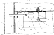
Fig. 1 is the structural front view of embodiment; Fig. 2-Fig. 4 is the structure principle chart of lockset, and wherein Fig. 2 is the A-A sectional view of Fig. 1, and Fig. 3 is the B-B sectional view of Fig. 2, and Fig. 4 is the C-C sectional view of Fig. 2, and Fig. 5 is A '-A ' sectional view of Fig. 1, and Fig. 6 is B '-B ' sectional view of Fig. 5.
Among the figure, 1, well lid ring support 2, well lid 3, lock body 4, latch 5, plug housing 6, catch 7, dial 8, open keyhole 9, key 10, spoons 11, lock core 12, sheath 13, mandrel 14, nut 15, screw 16, uncap and draw handle.
The specific embodiment:
With reference to accompanying drawing, this anti-stealing manhole cover comprises well lid 2 and well lid ring support 1, and being equipped with on well lid uncaps draws 16, and well lid 2 is that pivot pin is hinged with a side of well lid ring support 1, is provided with lockset at the well lid back side of its corresponding opposite side, on well lid, is provided with open keyhole 8.Lockset comprise by screw 15 be installed in lock body 3 on the well lid 2, be located at lock body inside a pair of key seat 5, can be on key seat move left and right latch 4, be connected with latch and the dialling 7 and can control the opening and closing device of latch displacement of perpendicular setting.Described opening and closing device comprises the lock core 11 that is arranged on the lock body 3, with the mandrel 13 of lock pin coaxial setting, be welded in catch 6 and spoon 10 key 9 that are meshed with lock core 11 between lock core and the mandrel.Described lock core is positive polygonal cylinder, the just polygon post hole of described spoon head for being engaged with.And sheath 12 is set on described lock core.
Its operating principle is: Fig. 2-Fig. 4 is a locking states: the front end of latch 4 is buckled on the well lid ring support 1, its end stop by catch 6 that well lid can not be opened, and because open keyhole 8 is very little, can't be with hand or TO lockset.In the time will opening well lid, must adopt key 9: spoon 10 is inserted open keyholes 8 and be enclosed within on the lock core 11, rotate key 9 then, make catch 6 transfer horizontal direction to from vertical direction, as Fig. 5-shown in Figure 6, stir 7 to the right again, make the front end of latch 4 break away from well lid ring support 1, at this moment, just can open well lid.
The utility model by changing the shape of lock core, as limit number or size, can be mixed with various key; For the identical manhole cover of of the same trade (teams and groups) management mutually, a plurality of manhole covers can shared identical key, with convenient management and operation.
Claims (4)
1, a kind of anti-stealing manhole cover, comprise well lid (2) and well lid ring support (1), being equipped with on well lid uncaps draws (16), well lid (2) is that pivot pin is hinged with a side of well lid ring support (1), the well lid back side in a side of its correspondence is provided with lockset, on well lid, be provided with open keyhole (8), it is characterized in that: lockset comprises by screw (15) and is installed in lock body (3) on the well lid (2), be located at a pair of key seat (5) of lock body inside, can be on key seat the latch (4) of move left and right, be connected with latch and the dialling (7) and can control the opening and closing device of latch displacement of perpendicular setting.
2, anti-stealing manhole cover according to claim 1 is characterized in that: the mandrel (13) that described opening and closing device comprises the lock core (11) that is arranged on the lock body (3), be provided with lock pin coaxial, be welded in the key (9) that catch (6) between lock core and the mandrel and spoon head (10) are meshed with lock core (11).
3, anti-stealing manhole cover according to claim 2 is characterized in that: described lock core is positive polygonal cylinder, the just polygon post hole of described spoon head for being engaged with.
4, according to claim 2 or 3 described anti-stealing manhole covers, it is characterized in that: sheath (12) is set on described lock core.
Priority Applications (1)
| Application Number | Priority Date | Filing Date | Title |
|---|---|---|---|
| CN 200620054733 CN2871656Y (en) | 2006-01-26 | 2006-01-26 | Safety manhole cover |
Applications Claiming Priority (1)
| Application Number | Priority Date | Filing Date | Title |
|---|---|---|---|
| CN 200620054733 CN2871656Y (en) | 2006-01-26 | 2006-01-26 | Safety manhole cover |
Publications (1)
| Publication Number | Publication Date |
|---|---|
| CN2871656Y true CN2871656Y (en) | 2007-02-21 |
Family
ID=37740002
Family Applications (1)
| Application Number | Title | Priority Date | Filing Date |
|---|---|---|---|
| CN 200620054733 Expired - Fee Related CN2871656Y (en) | 2006-01-26 | 2006-01-26 | Safety manhole cover |
Country Status (1)
| Country | Link |
|---|---|
| CN (1) | CN2871656Y (en) |
-
2006
- 2006-01-26 CN CN 200620054733 patent/CN2871656Y/en not_active Expired - Fee Related
Similar Documents
| Publication | Publication Date | Title |
|---|---|---|
| CN201125587Y (en) | Invisible second lock key anti-theft door lock | |
| CN110512655B (en) | Intelligent well lid | |
| CN201513017U (en) | Double-key hidden anti-theft alarm door lock | |
| CN111779365B (en) | A multi-stage magnetic control mechanism for a mechanical lock | |
| CN2716451Y (en) | Remote control anti-theft bolt | |
| CN207314393U (en) | A kind of anti-flood Sewage well cover | |
| CN2685489Y (en) | Opening handle for inspection well cover | |
| CN221255553U (en) | Kiln well cover with lock for theft prevention | |
| CN212389165U (en) | Well lid lock assembly, well lid lock and well lid | |
| CN201486274U (en) | Pickproof lock of drain well cover | |
| CN201292747Y (en) | Automatic alarm anti-theft door | |
| CN2786207Y (en) | Anti-theft well cover | |
| CN2440090Y (en) | Double-unlocking anti-theft lock | |
| CN111809665A (en) | An automatic feedback device for the state of an electric manhole cover | |
| CN2458348Y (en) | Anti-theft manhole cover | |
| CN220978110U (en) | Intelligent security well lid capable of preventing bottom intrusion | |
| CN1978849B (en) | Antitheft lock with clutching mechanism | |
| CN2895530Y (en) | Anti-theft well lid of steel-fiber concrete composite material | |
| CN221798516U (en) | Anti-theft lock for manhole cover | |
| CN2861408Y (en) | Theft-proof lock with clutch mechanism | |
| CN2913586Y (en) | Theft protection installation for oil field pore | |
| CN224259452U (en) | Well lid lock and well lid convenient to open | |
| CN2485389Y (en) | Multifunctional security lock for rolling shutter door | |
| CN2592721Y (en) | Antitheft manhole cover | |
| CN2816263Y (en) | Manhole antitheft lock |
Legal Events
| Date | Code | Title | Description |
|---|---|---|---|
| C14 | Grant of patent or utility model | ||
| GR01 | Patent grant | ||
| C17 | Cessation of patent right | ||
| CF01 | Termination of patent right due to non-payment of annual fee |
Granted publication date: 20070221 Termination date: 20100228 |