CN2861430Y - Window capable of orthogonal open and close - Google Patents
Window capable of orthogonal open and close Download PDFInfo
- Publication number
- CN2861430Y CN2861430Y CN 200520015389 CN200520015389U CN2861430Y CN 2861430 Y CN2861430 Y CN 2861430Y CN 200520015389 CN200520015389 CN 200520015389 CN 200520015389 U CN200520015389 U CN 200520015389U CN 2861430 Y CN2861430 Y CN 2861430Y
- Authority
- CN
- China
- Prior art keywords
- window
- sash
- hinge
- orthogonal direction
- fixed
- Prior art date
- Legal status (The legal status is an assumption and is not a legal conclusion. Google has not performed a legal analysis and makes no representation as to the accuracy of the status listed.)
- Expired - Fee Related
Links
Images


Abstract
A window can be opened and closed in orthogonal directions, the left side upper and lower end of the window sash are respectively connected to the frame via hinge, one of the hinges has the design of double-axial structure that can rotate in orthogonal directions, the fixed connecting plate is fixed to the window frame, the longitudinal axle lower end and the latitudinal axle can be connected through rotation, and also the flexible connecting block is covered and connected to the longitudinal axle. The fixed connecting plate of the other hinge is fixed to the flexible connecting plate of the window frame, and said fixed connecting plate is connected to the sliding groove mounted to the top of the window sash via a connecting rod in a sliding manner. The utility model can be revolved in the horizontal direction to form a traditional revolution window structure, and as well as be revolved a certain angle in the vertical direction to form a transom window, which provides options for the residents and overcomes the weak pointes of the existing push window, reducing the energy consumption of lowering temperature.
Description
Technical field:
The utility model relates to building field, particularly the improvement of the window of making of section bar.
Background technology:
Existing building constructions, the window that generally adopts section bar to make, the overwhelming majority is the flat push type structure, one of its shortcoming is that the area of windowing only accounts for 1/2nd of window frame area, influence the room ventilation situation, causing cooling power consumption increase.And traditional hinge through formula window, one of its advantage is that the area of windowing is big, especially summer, people wished that indoor generation cross-ventilation reduces room temperature, when the wind direction of open air just and during the window plane parallel, thisly horizontally rotate the formula sash and have, and the flat push type window just can't be accomplished this point to indoor air inducing effect.Only manage traditional hoirzontally rotating window and have more advantage, but because the existing shape that generally adopts has certain degree of difficulty on making,, and then follow the increase of air-conditioning consumption so the window installation of this structure reduces day by day.
Summary of the invention:
The purpose of this utility model provides a kind of sash can horizontally rotate folding, can vertically rotate the window of folding again.
The technical solution of the utility model is: sash sidepiece upper and lower side respectively is connected for hinge with window frame, it is characterized in that one of hinge is all rotating cross-compound arrangement of orthogonal direction, the junction plate of deciding of another hinge is fixed in window frame, and the plate that is dynamically connected is by connecting rod and the chute sliding connection that is contained in the sash top.The cross-compound arrangement hinge is loaded on the following side of sash.
The junction plate of deciding of the hinge of described cross-compound arrangement is fixed in window frame, and its lower end transverse axis is fixed on decides junction plate, and the longitudinal axis and transverse axis are rotatably connected, and the piece that is dynamically connected is connected in the longitudinal axis.
The two ends of support arm connect with sash top and connecting rod shank axle respectively.
The side of sash is equipped with rotatable handles, and the handle axle axle connects gear; A middle part has the tooth bar of several perforations by perforation and said gear engagement, be connected the respectively thin steel band of upper and lower transmission and walk around sash angle up and down of tooth bar two ends, the other end of the thin steel band of the last transmission transmission steel disc that is connected, transmission steel disc, the thin steel band of upper and lower transmission are respectively riveted a pin respectively, are loaded on the window frame profile inboard and corresponding to the position of pin draw-in groove are housed respectively respectively; At the connecting rod soffit one draw-in groove is installed, the draw-in groove sidewall has the breach for corresponding pin turnover.
The utility model sash lower end is rotated hinge with the twin shaft quadrature and is connected with window frame, the upper end is connected with the window frame hinge by connecting rod one chute structure, sash can be horizontally rotated constitute traditional structure window of flatting turn, the formation transom window can vertically turn an angle again, make things convenient for resident family to select, also overcome the not smooth drawback of existing flat push type window ventilation, reduced the cooling energy consumption.
Description of drawings:
Fig. 1 closes the state front view for the utility model embodiment closes.
Fig. 2 is Fig. 1 C-C sectional view.
Fig. 3 opens front view for sash horizontally rotates.
Fig. 4 is the vertical view of Fig. 3.
Fig. 5 is that sash vertically rotates an angle front view.
Fig. 6 is Fig. 5 left view
Fig. 7 is Fig. 5 vertical view.
Opening-closing structure schematic diagram when Fig. 8 opens ready position for sash is in.
Fig. 9 is a K frame partial enlarged drawing among Fig. 8.
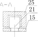
Figure 10 is an A-A sectional view among Fig. 9.
Figure 11 is Figure 10 right view.
Figure 12 is a B-B sectional view among Fig. 8.
Figure 13 is hinge 3 front views.
Figure 14 is a D-D sectional view among Figure 13.
Figure 15 is the handle front view.
Figure 16 is Figure 15 left view.
State diagram when Figure 17 is the loading and unloading handle.
The specific embodiment:
With reference to Fig. 1, Fig. 2, the frame of embodiment window frame 1 and sash 2 is made by section bar, setting-in double-layer glass 24 in sash 2 frames, limit, sash 2 left side is connected with window frame 1 by the hinge 4 of upper end, the hinge 3 of lower end, sash 2 positive right side of face are installed rotatable handles 5, the pass is closed state handle 5 and is in a position, and accordingly, the lock pin 10,12 and 21 that is loaded on sash 2 sides is in draw-in groove 13,11 cell walls inboard that is loaded on window frame 1 inboard and the draw-in groove 25 cell wall inboards that are loaded on the soffit of connecting rod 22 respectively.
With reference to Fig. 3, Fig. 4, sash 2 wraps page axle horizontal rotating opening becomes traditional commentaries on classics window state, at this moment need handle 5 to turn to the b position, accordingly, lock pin 12 highly is in the draw-in groove 13 cell walls outside, lock pin 10,21 is in the cell wall gap position of draw-in groove 11,25, and three lock pins break away from this position can open sash 2.
With reference to Fig. 5, Fig. 6, Fig. 7, make handle 5 turn to c under closing state in the pass, at this moment lock pin 12 is downwards more away from draw-in groove 13, and lock pin 10 then is positioned at draw-in groove 11 cell wall inboards, and lock pin 21 still is positioned at the cell wall gap position of draw-in groove 25; The plate 4.1 rivetings bar 22 repeatedly that is dynamically connected of hinge 4, the lock 17 that is installed on the other end of connecting rod 22 can slidably reciprocate in the chute 23 on being loaded on sash 2 upper side edge rail plates 16, support arm 19 1 ends are connected in sash 2 upper side edges with 20 of pins, and the other end is connected in the shaft (as shown in Figure 9) of connecting rod 22 with 18 of pins.Because lock pin 12,21 has broken away from draw-in groove 13,25, and lock pin 10 still is positioned at draw-in groove 11 cell wall inboards, so sash 2 can wrap the transverse axis 3.4 of page or leaf 3 and rotate (its structure as shown in figure 14) and constitute transom window, the angle that open sash 2 upper ends is decided by the sliding distance of connecting rod 22 tops in chute 23, sliding more to the right, angle is more little.
The opening and closing movement structure of sash 2 is with reference to Fig. 8~Figure 11, the rotating shaft driven wheel 5.3 of handle 5 rotate and with tooth bar 6 on the perforation engagement of being opened, tooth bar approaches steel band 8 with rivet 7 affixed upper and lower transmissions respectively in two ends about in the of 6,8 ', last transmission approaches the affixed lock pin 12 of steel band 8 near-ends, the affixed lock pin 21 of far-end also can will approach steel band 8 far-ends by rivet 14 and 15 riveted joints of transmission steel bar, and lock pin 21 is fixed on transmission steel bar 15 far-ends; Last transmission approaches the affixed lock pin 10 of steel band 8 far-ends.Corresponding to lock pin 21,12,10 positions, the inboard of the soffit of connecting rod 22, window frame 1 is fixed with draw-in groove 25,13,11 respectively, and wherein draw-in groove 11 respectively has breach corresponding to position b, draw-in groove 25 corresponding to position b, c, can be for lock pin 10,21 turnover.Handle 5 has a, b, three location of c, the a position is that the position is closed in the sash pass, the b position is the horizontal turn-off of sash position, the c position is a sash transit open position, promptly when handle 5 when the b position turns to a position, gear 5.3 drives upwards operation of tooth bar 6, be contained in the thin steel band 8 of underdrive, 8 ' on lock pin 10,12,21 respectively counterclockwise to move a segment distance, and each lock pin respectively is stuck in draw-in groove 25,13,11 cell wall inboards close sash 2 airtight passes, when handle 5 turns to the b position, tooth bar 6 drives thin steel band 8,8 ' and the operation down clockwise of each lock pin, each lock pin is in the corresponding b position of groove down, and at this moment lock pin 21,22,10 all can break away from draw-in groove, realize the sash unlatching of flatting turn; When handle forwards the c position to, tooth bar 6 drive thin steel band 8,8 ' and each lock pin continue to move to clockwise corresponding draw-in groove c position, at this moment lock pin 21,22 still breaks away from its draw-in groove, lock pin 10 then is positioned at draw-in groove 11 cell wall inboards, open downwards on realization sash top, and angle is opened in connecting rod 22 and support arm 19 controls.
Because thin up and down steel band 8,8 ' need walk around sash corner up and down, and up-bow and skew can take place in thin steel band when right-angled bend moves, so the side, two corners at sash 2 sets firmly rail bar 9, to guarantee thin steel band 8 smooth sliding back and forth in rail bar 9, as shown in figure 12.
With reference to Figure 15~Figure 17, handle 5 is screwed at sash front side.For avoiding screw to expose, the thin flap 5.1 that plastics are made is housed on the pedestal 5.2 of handle 5, when need loading and unloading handle, utilizes the elastic reaction of plastics will approach flap 5.1 half-twists, the screw hole of pedestal is exposed, will approach flap 5.1 after installing again and go back to the original place and get final product.
Claims (5)
- But 1, a kind of window of orthogonal direction folding, sash (2) sidepiece upper and lower side respectively is connected for hinge with window frame (1), it is characterized in that one of hinge (3) is all rotating cross-compound arrangement of orthogonal direction, the junction plate of deciding of another hinge (4) is fixed in window frame (1), and the plate that is dynamically connected (4.1) is by connecting rod (22) and chute (23) sliding connection that is contained in sash (2) top.
- But 2, the window of orthogonal direction folding according to claim 1 is characterized in that cross-compound arrangement hinge (3) is loaded on the following side of sash, and hinge (4) is loaded on the upper lateral part of sash.
- But 3, the window of orthogonal direction folding according to claim 2, the junction plate (3.2) of deciding that it is characterized in that the hinge (3) of cross-compound arrangement is fixed in window frame (1), its lower end transverse axis (3.4) is fixed on decides junction plate (3.2), the longitudinal axis (3.3) lower end and transverse axis (3.4) are rotatably connected, and the piece that is dynamically connected (3.1) is connected in the longitudinal axis (3.3).
- But 4, the window of orthogonal direction folding according to claim 1 is characterized in that the two ends of support arm (19) connect with sash (2) top and connecting rod (22) shaft axle respectively.
- 5, but the window of orthogonal direction folding according to claim 1, the front side that it is characterized in that sash (2) is equipped with rotatable handles (5), the handle axle axle connects gear (5.1), a middle part has the tooth bar (6) of several perforations by perforation and gear (5.1) engagement, on tooth bar (6) two ends are connected respectively, underdrive approaches steel band (8,8 ') and walk around upper right sash angle down, the other end that last transmission approaches steel band (8) the transmission steel disc (15) that is connected, transmission steel disc (15), last transmission approaches steel band (8), underdrive approaches steel band (8 '), and each rivets a pin (21 respectively, 12,10), be loaded on the window frame profile inboard corresponding to pin (12,10) each is equipped with a draw-in groove (13 respectively position, 11); At connecting rod (22) soffit draw-in groove (25) is installed, draw-in groove (11,25) sidewall respectively has the breach for corresponding pin (10,21) turnover.
Priority Applications (1)
| Application Number | Priority Date | Filing Date | Title |
|---|---|---|---|
| CN 200520015389 CN2861430Y (en) | 2005-10-09 | 2005-10-09 | Window capable of orthogonal open and close |
Applications Claiming Priority (1)
| Application Number | Priority Date | Filing Date | Title |
|---|---|---|---|
| CN 200520015389 CN2861430Y (en) | 2005-10-09 | 2005-10-09 | Window capable of orthogonal open and close |
Publications (1)
| Publication Number | Publication Date |
|---|---|
| CN2861430Y true CN2861430Y (en) | 2007-01-24 |
Family
ID=37659059
Family Applications (1)
| Application Number | Title | Priority Date | Filing Date |
|---|---|---|---|
| CN 200520015389 Expired - Fee Related CN2861430Y (en) | 2005-10-09 | 2005-10-09 | Window capable of orthogonal open and close |
Country Status (1)
| Country | Link |
|---|---|
| CN (1) | CN2861430Y (en) |
Cited By (5)
| Publication number | Priority date | Publication date | Assignee | Title |
|---|---|---|---|---|
| CN101481983B (en) * | 2009-01-22 | 2013-01-02 | 上海亮厦门窗有限公司 | Flat-opened bottom-hung window |
| CN103362390A (en) * | 2012-03-30 | 2013-10-23 | 株式会社Lixil | Installation structure of bearing fitting and inward tilt-turn window |
| CN105525816A (en) * | 2016-01-21 | 2016-04-27 | 瑞安市亚尔门窗五金有限公司 | Hinge structure of outward-opening and top-hinged double open type window |
| CN105649498A (en) * | 2016-01-30 | 2016-06-08 | 武汉大学 | Multi-state energy-saving window and three-state switching method |
| CN106014122A (en) * | 2016-07-29 | 2016-10-12 | 李新贵 | Door and window capable of being opened and closed in multiple directions |
-
2005
- 2005-10-09 CN CN 200520015389 patent/CN2861430Y/en not_active Expired - Fee Related
Cited By (5)
| Publication number | Priority date | Publication date | Assignee | Title |
|---|---|---|---|---|
| CN101481983B (en) * | 2009-01-22 | 2013-01-02 | 上海亮厦门窗有限公司 | Flat-opened bottom-hung window |
| CN103362390A (en) * | 2012-03-30 | 2013-10-23 | 株式会社Lixil | Installation structure of bearing fitting and inward tilt-turn window |
| CN105525816A (en) * | 2016-01-21 | 2016-04-27 | 瑞安市亚尔门窗五金有限公司 | Hinge structure of outward-opening and top-hinged double open type window |
| CN105649498A (en) * | 2016-01-30 | 2016-06-08 | 武汉大学 | Multi-state energy-saving window and three-state switching method |
| CN106014122A (en) * | 2016-07-29 | 2016-10-12 | 李新贵 | Door and window capable of being opened and closed in multiple directions |
Similar Documents
| Publication | Publication Date | Title |
|---|---|---|
| CN2861430Y (en) | Window capable of orthogonal open and close | |
| CN101042036A (en) | Slide-support mechanism, transmission device and electric internal-open and inner tilt window | |
| CN213205390U (en) | Solar environment-friendly door and window | |
| CN202299998U (en) | Energy-saving folding window | |
| CN2714766Y (en) | Rotatablely opened and closed sliding door and window | |
| CN2773537Y (en) | Air outlet device of air conditioner | |
| CN2525220Y (en) | Protective unit partition door of civil air defence | |
| CN2663619Y (en) | Sliding folding window | |
| CN201850967U (en) | Movable blind window | |
| CN2323108Y (en) | Top-hung and side-hung plastic-steel window | |
| CN102425358B (en) | Energy-saving folding window | |
| CN2723923Y (en) | Turnover type door stop reset device for double door refrigerator | |
| CN2687293Y (en) | Blind window | |
| CN200955305Y (en) | Sliding window switch device | |
| CN205936218U (en) | Foldable door and window starting and stopping mechanism | |
| CN210460373U (en) | Intelligent opening and closing window | |
| CN2851451Y (en) | Electrically-driven five-link gear for use in window | |
| CN215106360U (en) | Angle-adjustable curtain wall plate | |
| CN216197326U (en) | Casement window opening and closing angle fixing device | |
| CN220151160U (en) | Triangular lifting window opening structure | |
| CN2835502Y (en) | Side-hung window | |
| CN219365811U (en) | Rotary aluminium alloy door and window | |
| CN219733148U (en) | Hand-operated casement window device | |
| CN220353707U (en) | Novel hand flat-pushing window double-transmission mechanism | |
| CN2672254Y (en) | Multiple rail slide door and window |
Legal Events
| Date | Code | Title | Description |
|---|---|---|---|
| C14 | Grant of patent or utility model | ||
| GR01 | Patent grant | ||
| C17 | Cessation of patent right | ||
| CF01 | Termination of patent right due to non-payment of annual fee |
Granted publication date: 20070124 Termination date: 20091109 |