The utility model content
The purpose of this utility model is the deficiency that overcomes known technology, and a kind of fortune integral type bridge formation machine of setting a roof beam in place is provided.
The fortune described in the utility model integral type bridge formation machine of setting a roof beam in place comprises conveying-erecting machine and following nose girder machine.Described conveying-erecting machine comprises girder and forward and backward traveling wheels, girder is connected with vertical wheels vehicle frame of forward and backward traveling wheels, driver's cabin and back driver's cabin before the outer end of wheels vehicle frame is provided with respectively, described girder is provided with and connects the linkage and the hanging beam mechanism of the joist dolly of nose girder machine down, respectively is provided with two winches in the girder rear and front end; Described nose girder machine down comprises nose girder, the both sides, top of nose girder are equipped with and are used for the head rail that joist dolly and auxiliary supporting leg move, bottom guide track is equipped with on the both sides, bottom, nose girder vertically is divided into 7 sections, be connected with connecting pin by bolt between each sections, the 1st sections is equipped with rear support leg and support cylinder, the 4th sections is equipped with the power unit, 3rd, 5 sections are provided with the handling seat, the 7th sections is equipped with supporting leg suspension bracket and supporting leg draw-off mechanism, front end at nose girder is provided with major and minor supporting leg Lift-on/Lift-off System, and tail end is equipped with the folding suspension bracket of rear support leg.
Be connected to articulated form between vertical vehicle frame of described girder and forward and backward traveling wheels, and connect by the bracing frame transition.
Described forward and backward tire formula traveling wheels respectively have vertical wheels vehicle frame of two left and right sides apportions, the wheels vehicle frame is a vertical rectangular box beam, and wheel is promoted by linkage being installed under the wheels vehicle frame with steering mechanism, it is right that each wheels is equipped with the 6-12 wheel according to on-the-spot needs, each wheel comprises driving wheel to right with driven pulley to evenly arranging on vertically at front and back traveling wheels, the described wheel by steering mechanism, wheel is to 90 degree transfers, balancing cylinder, CD-ROM drive motor, steel bracing frame and tire wheel hub are formed.
The arrangement of the balancing cylinder of described wheels be preceding wheels all take turns right balancing cylinder and connect into a closed loop oil circuit, form a bit, all take turns back traveling wheels left side right balancing cylinder and right side all are taken turns right balancing cylinder and respectively connect into a closed loop oil circuit, form two points, each is taken turns the balancing cylinder of being furnished with and 3 balance sysmtes of the whole employing of front and back wheels.
Described linkage is positioned at the bracing frame place of girder front end, comprises Connection Block and power fast connecting joint.
Whether the operation that traveling wheels and back traveling wheels respectively are furnished with the monitoring conveying-erecting machine before described the orientation operation restriction system of depart,
Described winch is installed in respectively on the carriage on the face of fixing pre-girder rear and front end, and its overhead height is no more than the last plane of girder, and 2 winches of an end work alone, 2 winches of other end synchronous working that connects together.
The both sides at the forward and backward two ends of described girder are respectively arranged with the hanging beam mechanism that support can horizontal and vertical adjustment, each hanging beam mechanism is installed on preceding transverse bracket and the back transverse bracket, the front and back transverse bracket forms inverted T-shaped with main beam section respectively, back transverse bracket distributes along girder and discharges 1-3, each hanging beam mechanism has two bale handle points, hanging beam mechanism lay winding wire ropes, suspension pulley group and suspension bracket, described girder lower front also is equiped with the auxiliary boom hoisting of handling small members or instrument.
On described major and minor supporting leg Lift-on/Lift-off System comprises the supporting leg suspension bracket that is fixedly mounted on the nose girder and is fitted in the supporting leg suspension bracket, the little loop wheel machine that moves forward and backward of relative suspension bracket.
The bottom of described nose girder has lower transverse beam, the jigger guide rail is equipped with in its below, this guide rail is equipped with to hang gets major and minor supporting leg jigger, jigger is by the wire rope longitudinal traction, the bottom surface of described guide rail be higher than or etc. be higher than the bottom surface of nose girder bottom guide track, the supporting leg draw-off mechanism that is used for forward and reverse tractive wire rope is housed at the nose girder front end.
Described joist dolly has makes its transmission mechanism along the nose girder lengthwise movement, also is furnished with the jacking cylinder of the linkage that is used to connect the conveying-erecting machine front portion.
Described rear support leg is a portal support, and its support bottom constitutes by two sections, is connected with bolt with bearing pin between two sections, and both sides, rear support leg portal support top bossing supports nose girder as the support cylinder base; Two turning rollss with roller are equipped with at the intermediate transverse girder top of described portal support, and the horizontal slippage roller of this turning rolls can contact with support nose girder bottom guide track.
The fortune described in the utility model integral type bridge formation machine of setting a roof beam in place also has main supporting leg, auxiliary supporting leg and secondary supporting leg, and described main supporting leg comprises main supporting leg door frame, and main supporting leg roller is equipped with at this door frame top, and the bottom is furnished with spiral and supports; Described auxiliary supporting leg comprises steel framework, walking wheel carrier, bearing diagonal, movable supporting legs oscillating oil cylinder, hoist cylinder and erecting by overhang; Described secondary supporting leg comprises that the top of secondary supporting leg portal frame is equipped with the adjustment roller mount group of the secondary supporting leg roller of secondary supporting leg roller, sideslip oil cylinder and lateral adjustments top position, and its underpart is provided with support cylinder and spiral supports.
Also be provided with ground its base of auxiliary wheel device and directly be placed on abutment, roadbed or the bridge floor, fixing roller circulation roller on the base, side direction has directive wheel, about two roller seat couple together with pull bar.
Described front and back driver's cabin disposes to be controlled separately and mutual self-locking device, and the configuration remote controller fortune described in the utility model that replaces driver's cabin to control each action integral type bridge formation machine of setting a roof beam in place is a kind of multi-functional construction equipment that can realize hanging beam, fortune beam and the operation of setting a roof beam in place, can carry out the work of setting up of large-tonnage concrete box girder, and can satisfy the needs that carry out the bridge erection construction in the tunnel face, have the following advantages and good effect:
1. transport the most outstanding characteristics of integral type bridge formation machine of setting a roof beam in place, be about to get beam, Yun Liang, these three work of in the past being finished by 3 equipment of setting a roof beam in place concentrate on 1 complete equipment and finish, this makes usage ratio of equipment improve greatly, and the construction equipment gross investment (equipment total price) of a project has also been reduced a lot;
2. when conveying-erecting machine travels on bridge, the load of wheels always is distributed on the 2 adjacent hole beams before and after it, has reduced wheels to greatest extent and has acted on load on the 1 hole beam body;
The wheel of conveying-erecting machine to can be in the original place 90 degree turn to, make the fortune car of setting a roof beam in place not only can replace large-scale gantry crane at beam making field, and can be neatly laterally, vertically move, hang and get the case beam.Gantry crane is subjected to track restrictions, and vertically and horizontally walking is difficult for.When storage pad was big more, the quantity that is equipped with gantry crane also had to increase.And use 1 conveying-erecting machine can be in walking in the restricted region hardly, handling, loading and unloading;
Conveying-erecting machine each take turns being furnished with balancing cylinder, the front and back wheels are whole to adopt 3 balance sysmtes, guarantees that each wheel is no more than 2% to load deviation, and makes that the vehicle frame of conveying-erecting machine and main beam structure are not twisted, and guarantees that load is evenly distributed on 3.When running into obstruction (highly being not more than 150 millimeters) or pitting, this system can make load evenly distribute on each is taken turns again, and avoids local wheel to overload;
5. the hanging of conveying-erecting machine is moved and is turned to and all adopts the PLC electrichydraulic control, and the front and back drivers' cab can be controlled separately, self-locking mutually, and each action of control also can use a teleswitch;
6. the fortune fast convenience in integral type bridge formation machine conversion building site of setting a roof beam in place, the conveying-erecting machine nose girder machine of can slinging is down voluntarily walked.When finish a bridge set up work after, do not need auxiliary facility just can be transformed into next building site rapidly, will descend the nose girder machine in place.Particularly descend the leading section of nose girder machine that a gooseneck boom shape suspension bracket is arranged, several nose girder machine supporting legs down can be sling at front end, together be transferred to the building site, and supporting leg be arranged on the bridge pier of next bridge;
7. the fortune integral type bridge formation machine fortune frame construction process of setting a roof beam in place has demonstrated fully the characteristics that a set of equipment is finished beam making field hanging beam, building site fortune beam and on-the-spot three functions of building bridge in the lump.It has notable difference with bridge formation construction equipment that the fortune frame separates on structure and operation mechanism, one of its advantage is exactly much smaller than transporting the bridge formation construction equipment that frame separates on the size of height and width.When no matter whether carrying out the tunnel face bridge formation, its bridging operation flow process need not made any change.Equipment itself does not need to carry out any dismounting or assembling for adapting to the tunnel face bridge formation, does not need bridge, abutment and Tunnel Design and engineering to the tunnel face to propose any extra demand or do any engineered yet.
8. be connected the employing articulated manner between wheels and the conveying-erecting machine girder before and after the conveying-erecting machine, this has reduced the girder racking stress to greatest extent.When conveying-erecting machine rugged and rough or when having the soil in ramp to travel, because the front and back wheels are at a distance of tens meters, and wheels self are made of vertical rigid-frame, therefore, even wheels each the wheel on balancing cylinder is arranged, front and back wheels vehicle frame can not remain on the horizontal plane.And adopt articulated manner between front and back wheels and the conveying-erecting machine girder, just can alleviate girder effectively and change the twisting stress that causes because of the difference of front and back wheels ground level of living in.
9. be restriction conveying-erecting machine overall height, installation sites such as all hanging beam mechanisms, winch, power packages and switch board are all below the girder end face.As, hanging beam mechanism is installed in the both sides of girder, and winch is installed in the bottom, front and back end of girder, and power packages and switch board are installed on the traveling wheels vehicle frame.
10. during for the assurance construction, do not use other auxiliary facility (as loop wheel machine), equipment is furnished with a plurality of hanging devices and associated mechanisms as far as possible.As, the supporting leg suspension bracket of following nose girder machine front end, jigger guide rail under the nose girder moves jigger with hanging, the supporting leg draw-off mechanism of nose girder front end, the folding suspension bracket of following nose girder drive end unit (be used to hang get rear support leg), collapsible rear support leg and auxiliary supporting leg, the traversing turning rolls at rear support leg top, the hanging mechanism under the anterior girder of conveying-erecting machine etc.The transfer that picks and places for following each supporting leg of nose girder machine also has been equipped with ground auxiliary wheel device.
Be elaborated with reference to accompanying drawing below in conjunction with example, in the hope of objects and advantages of the present invention being able to more deep understanding.
The specific embodiment
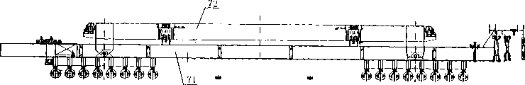
See figures.1.and.2, the fortune described in the utility model integral type bridge formation machine of setting a roof beam in place comprises conveying-erecting machine 72 and following nose girder machine 73.Described conveying-erecting machine 72 comprises girder 1 and forward and backward traveling wheels 8,7.Vertical wheels vehicle frame 41 of described girder and forward and backward traveling wheels 8,7 is seen Fig. 4.Driver's cabin 12 and back driver's cabin 6 before the outer end of wheels vehicle frame 41 is provided with respectively, described girder 1 are provided with and connect the linkage 14 and the hanging beam mechanism 3 of the joist dolly 21 of nose girder machine down, respectively are provided with two winches 4 in girder 1 rear and front end.
Referring to Fig. 3 and Fig. 5, described nose girder machine 73 down comprises nose girder 18, the both sides, top of nose girder 18 are equipped with and are used for the head rail 39 that joist dolly 21 and auxiliary supporting leg 29 move, bottom guide track 40 is equipped with on the both sides, bottom, nose girder 18 vertically is divided into 7 sections A, B, C, D, E, F, G, be connected with connecting pin by bolt between each sections, the 1st sections A is equipped with rear support leg 24 and support cylinder 23, the 4th sections D is equipped with power unit 26, the 3rd, 5 sections C, E is provided with handling seat 25, the 7th sections G is equipped with supporting leg suspension bracket 31 and supporting leg draw-off mechanism 33, is provided with the master at the front end of nose girder 18, secondary supporting leg Lift-on/Lift-off System, tail end is equipped with the folding suspension bracket 22 of rear support leg 24.
Referring to Fig. 2 and Fig. 5, be connected by bracing frame 13 transition between vertical wheels vehicle frame 41 of described girder 1 and traveling wheels 7,8, linkwork 42 is connected bracing frame 13 belows, by bearing pin 42 bracing frame 13 and wheels vehicle frame 41 are linked together, make between vertical wheels vehicle frame 41 of bracing frame 13 and wheels and can relatively rotate.
When conveying-erecting machine 72 rugged and rough or when having the soil in ramp to travel because the front and back wheels are at a distance of tens meters, and wheels self are made of vertical rigidity wheels vehicle frame 41, therefore, front and back wheels wheels vehicle frame 41 can not always remain on the horizontal plane.Even each wheel of wheels has balancing cylinder 43 can not alleviate girder 1 effectively because of the different twisting stresses that cause of two wheels place horizontal planes on 11.Linkwork 42 between vertical wheels vehicle frame 41 of conveying-erecting machine 72 girders 1 and front and back wheels is head it off effectively.
Described forward and backward tire formula traveling wheels 8,7 respectively have vertical wheels vehicle frame 41 of two left and right sides apportions, each wheels vehicle frame 41 is a vertical rectangular box beam, wheel to 11 and steering mechanism 9 be installed under the wheels vehicle frame 41, turn to and take turns to 11 self 90 ° turn to, promote by the oil cylinder linkage.Each wheels is equipped with 6-12 wheel to 11 according to on-the-spot needs.Each wheel is evenly arranged on vertically at front and back traveling wheels 8,7 to 11, comprises that driving wheel is to right with driven pulley.The described wheel 11 by steering mechanism 9, wheel be to 90 degree transfers 44, and balancing cylinder 43 is used to drive the driving hydraulic motor of wheels traveling, and steel bracing frame and tire wheel hub are formed.
Described steering mechanism 9 finishes by turning to oil cylinder to promote linkage.Wheel turns to by being installed in each self 90 degree and takes turns and the hydraulic jack on 11 is promoted wheel 90 degree transfers 44 are finished.Whole wheels were stressed evenly when balancing cylinder 43 can keep traveling wheels 7,8 to walk on rugged road surface.The steel bracing frame is supporting whole the wheel 11.
Each of described front and back traveling wheels 8,7 taken turns being furnished with balancing cylinder 43, hydro-cushion oil cylinder 43 forms a supported at three point system: all take turns preceding traveling wheels 8 right balancing cylinder 43 and connect into a closed loop oil circuit, form a bit, all take turns back traveling wheels 7 left sides right balancing cylinder 43 and right side all are taken turns right balancing cylinder 43 and respectively connect into a closed loop oil circuit, form two points.So just, constitute two at conveying-erecting machine 72 the rear portions independently strong point and an anterior strong point independently, formed 3 balance sysmtes.Each takes turns conveying-erecting machine 72 and adopts 3 balance sysmtes to 11 balancing cylinders of being furnished with 43 and front and back wheels are whole, the linkwork 42 of aforesaid in addition wheels vehicle frame 41, guaranteed that each wheel is no more than 2% to 11 load deviation, and made the wheels vehicle frame 41 of conveying-erecting machine and main beam structure not be subjected to additional twisting stress effect.When running into obstruction or pitting, this system can make load evenly distribute on each is taken turns again, and avoids local wheel to 11 overload.
The power unit 5 and the switch board of conveying-erecting machine 72 are located on the wheels vehicle frame 41.Power unit 5 comprises diesel engine and hydraulic power group for equipment provides power.Switch board is furnished with the various electrical device movable of manipulation and is connected.
Described linkage 14 is positioned at bracing frame 13 places of girder front portion, to connect the joist dolly 21 of nose girder machine down.This linkage 14 comprises Connection Block and power fast connecting joint 45.
Referring to Figure 12, Figure 17 and Figure 25, after joist dolly 21 tops are arrived in traveling wheels 8 travelings before the conveying-erecting machine 72, be connected with the power fast connecting joint 45 on the joist dolly 21, for the jacking cylinder on the joist dolly 21 20 provides power, jacking cylinder 20 can be propped up traveling wheels 8 before the conveying-erecting machine, and conveying-erecting machine 72 anterior weight are transferred to joist dolly 21.
Traveling wheels 8 and back traveling wheels 7 respectively are furnished with directed operation restraint device (commercially available) before described, and promptly direction position probe can be monitored road surface or bridge floor specific identifier.When conveying-erecting machine 72 walking when needs are controlled away line position regional, in case the traveling route departs from the scope of setting, probe will transmit signal and notify the driver to adjust conveying-erecting machine 72 direction of travels to driver's cabin.
Described conveying-erecting machine 72 is furnished with remote control (commercially available), and when conveying-erecting machine 72 work, the operator can be in the action of the conveying-erecting machine 72 of position manipulation easily.Remote control comprises instruction transmitter (remote controller) and is installed in recipient on the conveying-erecting machine 72, becomes to transmit data by highly dense code conversion between the instruction emitter and receiver and finishes.
Referring to Fig. 2 and Fig. 6, described girder 1 is a girder steel, and section form is a rectangle, and girder 1 is divided into several sections, connects by bolt between sections.Girder steel is provided with strengthens gusset and floor.Be respectively arranged with transverse bracket 15 and the back transverse bracket 16 that supports hanging beam mechanism 3 in the both sides at the forward and backward two ends of girder, the front and back transverse bracket all is linked to be inverted T-shaped mechanism with girder.According to application conditions and concrete box beam length, back transverse bracket 16 distributes along girder 1 and discharges 1-3.
Be the requirement of satisfying handling, setting up different length case beam, when needing with hanging beam mechanism 3 conversion lengthwise positions.
Described hanging beam mechanism 3 laterally, vertically is connected with oil cylinder, can adjust hanging beam mechanism 3 within the specific limits laterally, vertically move.To guarantee when falling beam, concrete box girder being carried out the position adjustment.Hanging beam mechanism 3 lay winding wire ropes are being suspended assembly pulley and suspension bracket 2 in midair.Each hanging beam mechanism 3 is installed on the girder by preceding transverse bracket 15 and back transverse bracket 16, and each hanging beam mechanism has two bale handle points, 4 bale handle points altogether in such two hanging beam mechanisms.
Referring to Fig. 5, on girder 1 rear and front end face, be fixedly connected with winch carriage 17, respectively be provided with 2 winches 4 on it, 2 winches of one end work alone, 2 winches 4 of the other end are associated in synchronous working together, so that whole jacking system constitutes 3 balance sysmtes, like this at hanging beam, Yun Liang with when falling beam, all the time can be kept a plane stress by the box beam, make by the box beam and be not subjected to the twisting stress effect.The overhead height that is installed in the winch 4 on the carriage is no more than the last plane of girder 1.
Referring to Fig. 2, described girder is equiped with auxiliary boom hoisting 10 under 1 front portion, is used to finish back works such as handling small members or instrument.
Referring to Fig. 7, Fig. 8 and Fig. 9, described nose girder 18 is main bodys of following nose girder machine 73, carries each workpiece.Referring to Figure 15, Figure 16, Figure 24 and Figure 29, major and minor supporting leg Lift-on/Lift-off System is used for promoting and the major and minor supporting leg of handling.Folding suspension bracket 22 is to open when in the end a hole concrete box girder sets up, and rear support leg 24 can be hung oneself from abutment and get, and vacates the Luo Liang position.
On described major and minor supporting leg Lift-on/Lift-off System comprises the supporting leg suspension bracket 31 that is fixedly mounted on the nose girder 18 and is fitted in supporting leg suspension bracket 31, the electronic little loop wheel machine 32 that moves forward and backward of relative suspension bracket.Folding suspension bracket 22 is to open when in the end a hole concrete box girder sets up, and rear support leg 24 can be hung oneself from abutment and get, and vacates the Luo Liang position.
Referring to Fig. 8, the bottom of nose girder 18 has across-linked beam 46, and two jigger guide rails 50 are equipped with in its below.Two guide rails respectively are equipped with a jigger 51, and jigger 51 can hang gets major and minor supporting leg.These guide rail 50 bottom surfaces be higher than or etc. be higher than the bottom surface of nose girder bottom guide track 40.Jigger 51 is by the wire rope longitudinal traction.At following nose girder machine 73 front ends supporting leg draw-off mechanism 33 and pulley are housed, are used for forward and reverse tractive wire rope and jigger 51, and then shift major and minor supporting leg.
Be furnished with a power unit 26 in the nose girder 18 the mobile power that provides for major and minor supporting leg is provided.This power unit 26 comprises motor and hydraulic power station.
Described joist dolly 21 can walk to the F section by chain-drive mechanism 19 along track from the A segment trailer.This joist dolly 21 comprises frame, jacking cylinder 20 and transmission mechanism 19.Transmission mechanism drives it and vertically moves.Described transmission mechanism can be a chain-drive mechanism 19, and the chain two ends of this mechanism are separately fixed on the afterbody and F section of A section, and chain connects through a Samsung sprocket system and 21 holders of joist dolly.Described joist dolly 21 is furnished with four jacking cylinders 20, supports joist dolly linkage 14 by this four jacking cylinder 20, referring to Fig. 4.8 jackings of conveying-erecting machine 72 front walking wheel groups are got up, the weight of conveying-erecting machine 72 front portions is all transferred on the joist dolly 21.The power of chain-drive mechanism 19 comes from the power source at conveying-erecting machine 72 front walking wheel groups 8 places by power jointing 45.Joist dolly 21 has two functions:
A. when the weight of conveying-erecting machine 72 front portions was all transferred on the joist dolly 21, joist dolly 21 was being carried the walking on the nose girder 18 of following nose girder machine 73 of conveying-erecting machine front portion on the back.
B. when the weight of conveying-erecting machine 72 front portions is all transferred on the joist dolly 21, by braking conveying-erecting machine rear walking wheel group 7, and separate the constraint of taking off the nose girder machine, the nose girder 18 that can order about down the nose girder machine seesaws.
Described rear support leg 24 can be mentioned by rear support leg hanging device 49 nose girder 18 times.Rear support leg 24 can link together with nose girder 18 structures during bridge formation.Rear support leg 24 is a portal support 48, and its support bottom constitutes by two sections, is connected with bearing pin with bolt between two sections, therefore can fold.Both sides, rear support leg portal support 48 top bossing supports nose girder 18 as support cylinder 23 bases.Two turning rollss with roller 47 of laterally slippage are equipped with at the intermediate transverse girder top of portal support 48.When needs control down the supporting leg suspension bracket 31 of nose girder machine hang (referring to Figure 30) when getting main supporting leg 28, turning rolls outwards moves laterally to the position, and is fastenedly connected with intermediate transverse girder, roller 47 contact nose girders 18 bottom guide tracks 40, and support stressed.
Referring to Fig. 8, the fortune described in the utility model integral type bridge formation machine of setting a roof beam in place also has main supporting leg 28, auxiliary supporting leg 29 and secondary supporting leg 35.Described main supporting leg 28 can vertically move along nose girder 18 bottoms, supports nose girder machine 73 down, comprises main supporting leg door frame 52, and main supporting leg roller 27 is equipped with at these door frame 52 tops, and the bottom is furnished with spiral and supports 54, so that regulate height.Main supporting leg 28 can be sling by the jigger 51 of nose girder 18 bottoms, and along jigger guide rail 50 handlings of nose girder 18 bottoms to assigned address.
Described auxiliary supporting leg 29 only is used for when major and minor supporting leg is shifted as support (referring to Figure 14 temporarily, Figure 15, Figure 16 and Figure 24), form by steel framework, walking wheel carrier 55, bearing diagonal 57, movable supporting legs oscillating oil cylinder 56, hoist cylinder 53, erecting by overhang 58 etc.Auxiliary supporting leg 29 with walking wheel carrier can vertically move along nose girder 18 top rail.When auxiliary supporting leg 29 supported, the walking wheel carrier was supported on the moving track, connect and 18 of nose girders hang drawing device, the walking wheel carrier is closely contacted with nose girder 18 end face tracks.Drive movable supporting legs oscillating oil cylinder 56, make that movable supporting legs and fixed supporting leg are vertical to be connected, be supported on the pier.Support oil cylinder can be regulated height.
Referring to Fig. 9, described secondary supporting leg 35 comprises secondary supporting leg portal frame 60, the roller mount the adjusted group 64 of secondary supporting leg roller 65, sideslip oil cylinder 61 and lateral adjustments top secondary supporting leg roller 34 positions is equipped with at its top, and its underpart is provided with support cylinder 62 and spiral supports 63, so that regulate height.When curve is set a roof beam in place work, but nose girder 18 positions are adjusted in 65 left and right sides slippages of secondary supporting leg roller.This pair supporting leg 35 can also be sling by the following jigger 51 of nose girder machine 73 bottoms, and along jigger guide rail 50 handlings of nose girder 18 bottoms to assigned address (referring to Figure 15 and Figure 24).
Referring to Fig. 4, the fortune described in the utility model integral type bridge formation machine of setting a roof beam in place also is provided with ground auxiliary wheel device 36, when by Figure 10 to Figure 13 and Figure 25 when Figure 37 works, be again the antifriction guide holder of nose girder 18 front and back operation as nose girder machine 73 down at the strong point of abutment, roadbed or bridge floor.This device comprises roller circulation roller seat, is installed in the directive wheel 37 of base side direction, about two roller seat couple together with pull bar 38.During use, base directly is placed on abutment, roadbed or the bridge floor.
Totally 4 of the handling seats 25 that the C section of nose girder 18 and E section are placed, it can connect suspender.When pressing Figure 10, when Figure 38 and Figure 39 work, the lifting when being used for conveying-erecting machine 72 and slinging down 73 operations of nose girder machine.
Conveying-erecting machine 72 and following nose girder machine 73 are formed the fortune integral type bridge formation machine of setting a roof beam in place, and replace the large-tonnage bridge formation machine of the large-tonnage haulage vehicle that adopts in the large-tonnage bale handle equipment (lifting beam machine or gantry crane) that adopts the precast beam field, the transportation (along roadbed or set up the beam delivering machine or the beam transportation vehicle of bridge floor fortune beam) and the employing of concrete prefabricated box beam erection position.On 26S Proteasome Structure and Function, take into full account the demand of job site actual conditions, all shortcomings of the bridging equipment of then satisfactory solution fortune frame separate mode.
Fortune described in the utility model sets a roof beam in place that integral type bridge formation machine will hang, the function of fortune, frame collects on a set of equipment, makes the bridge formation machine build bridge at the scene on this link, and equipment does not have the function repetitive structure, as braced structures.Thereby this has also just determined to transport the application that the integral type bridge formation machine of setting a roof beam in place can adapt to multiple construction occasion.
Referring to Figure 10 to Figure 23 and Figure 33 to Figure 39, fortune is set a roof beam in place integral type bridge formation machine when carrying out the tunnel face bridge formation, equipment itself does not need to carry out any dismounting or assembling, also do not need bridge, abutment and Tunnel Design to the tunnel face and engineering to propose any extra demand or do any engineeredly, its bridging operation flow process can be equal to conventional bridging operation flow process fully.In fact, the tunnel face does not constitute any influence to its bridging operation.
Compare with the bridge formation mode that the fortune frame separates, transport one of the very outstanding advantage of integral type bridge formation machine of setting a roof beam in place, be that complete machine structure width and height dimension are little, hanging beam passes through the tunnel and has enough safe operation spaces, thereby can adapt to hanging beam effectively and pass through the tunnel and carry out tunnel face bridge formation operating mode.
The assembling of these mechanisms make nose girder machine down operation, conversion pier position, set up first hole and last two hole beams and shift bridge formation process safeties such as building site reliable, simple to operate, holding time is short, labour intensity is little, has solved the difficult problem of equipment displacement in the construction of building bridge effectively.
The fortune described in the utility model integral type bridge formation machine of setting a roof beam in place satisfies following the requirement:
1. prefabricated railway (highway) two-wire concrete boxlike beam can be sling from the pedestal of prefabricated (depositing) field, be implemented allocation and transportation transfer work;
2. can be with the handling of prefabricated railway (highway) two-wire concrete boxlike beam to setting up the place, and the work that builds a bridge;
3. when fortune during beam, can be at the railway bed of causeway slag (highway subgrade) not and travelled on the bridge floor of the good bridge of frame, roadbed and bridge floor are not caused any infringement;
4. fortune is during beam, can be under the situation that does not change railway (or highway) tunnel type design, and take concrete box girder or take down the nose girder machine and pass through the tunnel;
5. can set up from first hole all concrete prefabricated case beams voluntarily, and need not other auxiliary facility to last hole;
6. can set up the bridge of tunnel face, and need not change, adjustment or the dismounting fortune any parts of integral type bridge formation machine self of setting a roof beam in place, also need not other auxiliary facility or the working design of tunnel face is proposed specific (special) requirements;
7. conveying-erecting machine can be taken down the nose girder machine voluntarily and shift the building site of setting a roof beam in place;
8. the configuration rotating disk can be reversed end for end on roadbed, carries out reverse bridge erection.
The fortune described in the utility model integral type bridge formation machine of setting a roof beam in place can adapt to following condition of work:
1. environment temperature:>-15 ℃;
2. maximum wind power grade during operation: eight grades (72 kilometers/hour of wind speed);
3. satisfy the lighting installation that sets up operation night;
4. can normally move and set up work on bridge and circuit 3% ramp;
5. but handling, set up the large-tonnage concrete box girder.
The set a roof beam in place course of work step of integral type bridge formation machine of fortune described in the utility model is as follows:
The first step is laid down the nose girder machine, referring to Figure 10-Figure 13:
1) Beam transportation vehicle is taken down the nose girder machine and is walked to the first bridge platform, 68 places.To be suspended in down master on the nose girder machine end suspension bracket 31, rear support leg 28,24 on abutment 68;
2) lay ground auxiliary wheel device 36 on the roadbed 70.Then, will descend the nose girder machine to be placed on ground auxiliary wheel device 36 and the main supporting leg roller 27.Joist dolly 21 on conveying-erecting machine and the following nose girder machine links;
3) wheels 7 brakings behind the conveying-erecting machine.Control nose girder 18 moves forward.Secondary supporting leg 35 is placed on the bridge pier 69;
4) control nose girder 18 reach is positioned at the top of front bridge pier 69 until nose girder 18 front ends, and following nose girder drive end unit stops when arriving assigned address.Conveying-erecting machine and joist dolly 21 are thrown off, and return beam making field and get beam.Auxiliary supporting leg 29 fall backs are to secondary supporting leg 35 sides;
In second step, following nose girder machine supporting leg is in place, referring to Figure 14-Figure 16:
1) the auxiliary supporting leg 29 of system is supported on the bridge pier 69 stressed;
2) secondary supporting leg 35 moves on the next bridge pier 69, and anchoring;
3) main supporting leg 28 reaches, the front side of bridge pier 69 in the middle of being installed in, and anchoring;
The 3rd step, feeding beam, referring to Figure 17-Figure 18:
1) conveying-erecting machine transports concrete box girder 71 to end of the bridge, and with the contraposition of following nose girder machine, the joist dolly linkage 14 at traveling wheels 8 places links with joist dolly 21 before the conveying-erecting machine;
2) conveying-erecting machine and joist dolly 21 simultaneously downward nose girder machine front ends travel, and walk to the Luo Liang position;
The 4th step, pump nose girder, referring to Figure 19-Figure 20:
1) back traveling wheels 7 brakings, control nose girder 18 moves ahead;
2) control nose girder 18 continues to move ahead, and vacates concrete box girder 71 Luo Liang positions, prepares beam;
The 5th step, the beam that falls, referring to Figure 21, concrete box girder 71 beam that falls is in place;
The 6th step, the conveying-erecting machine rollback, referring to Figure 22-Figure 23:
1) control nose girder 18 retreats on the bridge that frame is good, and following nose girder machine tail end arrives at assigned address;
2) traveling wheels 8 land before the conveying-erecting machine, and joist dolly linkage 14 is thrown off with joist dolly 21, and conveying-erecting machine is return;
In the 7th step, following nose girder machine supporting leg resets, and referring to Figure 24, auxiliary supporting leg 29 supports stressed, and major and minor supporting leg moves on the next bridge pier 69, prepares setting up of next concrete box girder 71.8~15 processes of repetition are carried out setting up of next concrete box girder 71;
In the 8th step, set up in bridge hole second from the bottom, referring to Figure 25-Figure 28:
1) the supporting leg suspension bracket 31 of nose girder machine front end is sling secondary supporting leg 35 down.Following nose girder machine front end is supported on before the abutment 68 on the auxiliary wheel device 36 on the roadbeds 70.Conveying-erecting machine is taken concrete box girder 71 and is run to down on the nose girder machine, the operation of setting a roof beam in place;
2) control nose girder 18 moves ahead, and vacates concrete box girder 71 Luo Liang positions;
3) concrete box girder 71 beam that falls is in place;
4) control nose girder 18 retreats to assigned address, and traveling wheels 8 moved backward before joist dolly 21 supported conveying-erecting machine;
In the 9th step, set up in bridge hole last, referring to Figure 29-Figure 37:
1) main supporting leg 28 moves ahead, and is supported on the abutment 68;
2) bridge floor is laid auxiliary wheel device 36, in order to support nose girder 18.Control nose girder 18 continues to retreat.The supporting leg suspension bracket 31 of nose girder 18 front ends is sling main supporting leg 28;
3) control nose girder 18 moves ahead, and arrives assigned address until following nose girder machine tail end.Traveling wheels 8 land before the conveying-erecting machine, and conveying-erecting machine and joist dolly 21 are thrown off, and return, and go beam making field to get concrete box girder 71;
4) conveying-erecting machine is taken concrete box girder 71 to following nose girder machine place, and traveling wheels 8 are in place with following nose girder machine before the conveying-erecting machine, and link with joist dolly 21.Conveying-erecting machine and joist dolly 21 move ahead simultaneously;
5) the place ahead roadbed 70 is laid auxiliary wheel device 36, traveling wheels 7 brakings behind the conveying-erecting machine, and control nose girder 18 moves ahead;
6) rear support leg 24 is placed on the abutment 68, nose girder 18 afterbody suspension brackets 22 are opened, and control nose girder 18 continues to be forwarded to the position that can sling rear support leg 24 rear support leg 24 of slinging;
7) rear support leg 24 is folding to the inside, and control nose girder 18 continues to move ahead;
8) control nose girder 18 moves ahead, and vacates concrete box girder 71 Luo Liang positions, and it is in place to prepare concrete box girder 71 beam that falls;
9) concrete box girder 71 fall beam in place after, traveling wheels 8 land before the conveying-erecting machine, conveying-erecting machine and 21 disengagements of joist dolly;
In the tenth step, the fortune integral type bridge formation machine of setting a roof beam in place shifts the building site, referring to Figure 38-Figure 39:
1) suspension bracket 22 of nose girder machine tail end puts down rear support leg 24 down, and conveying-erecting machine moves ahead, the nose girder machine of slinging down;
2) conveying-erecting machine is taken down the nose girder machine and is retreated, the suspension bracket 31 of the following nose girder machine front end rear support leg 24 of slinging.Conveying-erecting machine takes down the nose girder machine and each supporting leg is transferred to next building site.