CN2701595Y - Steel structure high strength bolt and connecting plate changing tool - Google Patents
Steel structure high strength bolt and connecting plate changing tool Download PDFInfo
- Publication number
- CN2701595Y CN2701595Y CN 200420022413 CN200420022413U CN2701595Y CN 2701595 Y CN2701595 Y CN 2701595Y CN 200420022413 CN200420022413 CN 200420022413 CN 200420022413 U CN200420022413 U CN 200420022413U CN 2701595 Y CN2701595 Y CN 2701595Y
- Authority
- CN
- China
- Prior art keywords
- plate
- steel
- plates
- jacks
- connecting plate
- Prior art date
- Legal status (The legal status is an assumption and is not a legal conclusion. Google has not performed a legal analysis and makes no representation as to the accuracy of the status listed.)
- Expired - Fee Related
Links
Images
Landscapes
- Conveying And Assembling Of Building Elements In Situ (AREA)
Abstract
本实用新型公开了一种钢结构高强螺栓及连接板更换工具。它包括两个千斤顶,其特点是在两个千斤顶的上、下方各设有一个的板块,该板块的中央有一个方孔,位于两个千斤顶一侧的两个板块方孔内各插入并榫紧两个活动的楔子。当拆卸高强螺栓及连接板时,由于连接板对钢板件产生的摩擦力被楔子所代替,将钢板件与连接板之间的摩擦力转载到千斤顶上,使高强螺栓及连接板不承受力而能拆卸更换。本实用新型结构简单,操作方便,具有快捷、安全、成本低、不损伤钢板件结构的优点。
The utility model discloses a steel structure high-strength bolt and a connecting plate replacement tool. It includes two jacks, and its characteristic is that there is a plate above and below the two jacks, and there is a square hole in the center of the plate, which is inserted into the square holes of the two plates on the side of the two jacks Tighten the two movable wedges. When the high-strength bolts and connecting plates are disassembled, because the friction force generated by the connecting plate on the steel plate is replaced by a wedge, the friction between the steel plate and the connecting plate is transferred to the jack, so that the high-strength bolts and connecting plates do not bear the force. Can be disassembled and replaced. The utility model has the advantages of simple structure, convenient operation, quickness, safety, low cost and no damage to the steel plate structure.
Description
技术领域technical field
本实用新型涉及大型钢结构中高强螺栓与连接板的更换技术。The utility model relates to the replacement technology of high-strength bolts and connecting plates in large-scale steel structures.
背景技术Background technique
在大型钢结构中,例如起重机钢结构,该结构钢板件与钢板件的连接,都是通过高强度螺栓及连接板的作用,给予钢板件预紧压力,连接板对钢板件之间形成摩擦力,从而将钢板件连接在一起。也可以说高强度螺栓连接就是摩擦连接。然而,高强度螺栓预紧力的大小随时间而逐渐减少。另外,年久产生的锈蚀使螺栓的预紧力大幅度下降。因此高强度螺栓及连接板经过较长时间使用后必须更换。但是对大型钢结构设备无法运到加工厂去更换,只能在使用现场更换,且困难很大。现有更换高强度螺栓及连接板采用钢板件与钢板件之间用其它钢制构件相互焊接连在一起。这样对钢结构产生了内应力损伤,而且费用较大。In a large steel structure, such as a crane steel structure, the connection between the structural steel plate and the steel plate is through the action of high-strength bolts and the connecting plate, which gives the steel plate a pre-tightening pressure, and the friction between the connecting plate and the steel plate is formed. , thereby joining the steel plates together. It can also be said that the high-strength bolt connection is a friction connection. However, the magnitude of the pretightening force of high-strength bolts gradually decreases with time. In addition, the long-term corrosion has greatly reduced the pre-tightening force of the bolts. Therefore, high-strength bolts and connecting plates must be replaced after a long period of use. However, large-scale steel structure equipment cannot be transported to the processing plant for replacement, but can only be replaced at the use site, and it is very difficult. Existing replacement of high-strength bolts and connecting plates adopts steel plate parts to be welded together with other steel components between the steel plate parts. This produces internal stress damage to the steel structure, and the cost is relatively large.
发明内容Contents of the invention
针对现有技术存在着不足之处,本实用新型提供一种钢结构高强螺栓及连接板更换工具。它能够快速而有效地更换高强螺栓与连接板,防止钢结构损伤和性能下降。Aiming at the deficiencies in the prior art, the utility model provides a tool for replacing high-strength bolts and connecting plates of a steel structure. It enables fast and efficient replacement of high-strength bolts and connecting plates, preventing structural steel damage and performance degradation.
本实用新型是通过以下的技术方案实现的,它包括两个千斤顶,其结构要点是在两个千斤顶上、下方各设有一个板块,该板块的中央有一个方孔,板块是由两个可拆卸的半爿连接而成,位于两个千斤顶一侧的两个板块方孔内各设有两个活动的楔子。The utility model is realized through the following technical proposals. It includes two jacks. The disassembled half valves are connected, and two movable wedges are respectively arranged in the square holes of the two plates on one side of the two jacks.
上述两个可拆卸的半爿板块可以用钢板钩连接,也可以用钢板、螺钉连接。Above-mentioned two detachable half valve plates can be connected with steel plate hook, also can be connected with steel plate, screw.
本实用新型用板块、千斤顶、楔子组成的简单工具结构,通过方便的操作,用千斤顶支承板块,板块方孔内由活动楔子榫紧。将钢板件与连接板之间的摩擦力转载到千斤顶上,使高强螺栓及连接板不承受力而能拆卸更换。具有快捷、安全、成本低、不损伤钢板件结构的优点。The utility model uses a simple tool structure composed of plates, jacks and wedges. Through convenient operation, the jack supports the plates, and the square holes of the plates are tightened by movable wedges. The friction force between the steel plate and the connecting plate is transferred to the jack, so that the high-strength bolts and connecting plate can be disassembled and replaced without bearing the force. The utility model has the advantages of quickness, safety, low cost and no damage to the steel plate structure.
附图说明Description of drawings
以下将结合附图和实施例对本实用新型作进一步的详细说明。The utility model will be further described in detail below in conjunction with the accompanying drawings and embodiments.
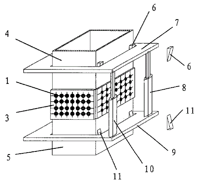
图1是本实用新型的结构示意图。Fig. 1 is the structural representation of the utility model.
图2是本结构示意图中钢结构连接局部剖面图。Fig. 2 is a partial sectional view of the steel structure connection in the structural schematic diagram.
具体实施方式Detailed ways
图1和图2中,以起重机为例,标号中的高强螺栓1和连接板2、3及钢板件4、5是表示该设备的局部钢结构连接关系。标号中楔子6、11和板块7、9及千斤顶8、10是本实施例的更换工具。工作时,先将板块7、9的两半爿分别套在要更换的高强螺栓1及连接板2、3一段的钢板件4、5位置上,并把板块7、9各自连接成一体,它可以用钢板钩或用钢板、螺钉连接,本实施例用钢板钩连接。用各两个楔子6、11插入在板块7、9的方孔内一侧,使板块7、9与钢板件4、5榫紧。千斤顶8、10放在板块7、9中间,且置于楔子6、11一侧,让千斤顶8、10支撑板块,就能拆卸靠近千斤顶8、10一面的高强螺栓1及连接板2、3。由于连接板2、3对钢板件4、5产生的摩擦力被楔子6、11所代替,也就是说力通过楔子6、11来支撑钢板件4、5,楔子6、11上的力转载到千斤顶8、10上,由千斤顶8、10来承受。这样就可方便地更换高强螺栓1和连接板2、3。In Fig. 1 and Fig. 2, taking a crane as an example, the high-
Claims (2)
Priority Applications (1)
| Application Number | Priority Date | Filing Date | Title |
|---|---|---|---|
| CN 200420022413 CN2701595Y (en) | 2004-04-29 | 2004-04-29 | Steel structure high strength bolt and connecting plate changing tool |
Applications Claiming Priority (1)
| Application Number | Priority Date | Filing Date | Title |
|---|---|---|---|
| CN 200420022413 CN2701595Y (en) | 2004-04-29 | 2004-04-29 | Steel structure high strength bolt and connecting plate changing tool |
Publications (1)
| Publication Number | Publication Date |
|---|---|
| CN2701595Y true CN2701595Y (en) | 2005-05-25 |
Family
ID=34770366
Family Applications (1)
| Application Number | Title | Priority Date | Filing Date |
|---|---|---|---|
| CN 200420022413 Expired - Fee Related CN2701595Y (en) | 2004-04-29 | 2004-04-29 | Steel structure high strength bolt and connecting plate changing tool |
Country Status (1)
| Country | Link |
|---|---|
| CN (1) | CN2701595Y (en) |
Cited By (2)
| Publication number | Priority date | Publication date | Assignee | Title |
|---|---|---|---|---|
| CN101670574B (en) * | 2008-09-10 | 2012-01-04 | 鞍山钢铁集团公司 | Tool for quickly replacing brake pad of crane |
| CN106836027A (en) * | 2017-04-11 | 2017-06-13 | 北京市市政工程设计研究总院有限公司 | A kind of steel box-girder splice plate more changing device |
-
2004
- 2004-04-29 CN CN 200420022413 patent/CN2701595Y/en not_active Expired - Fee Related
Cited By (3)
| Publication number | Priority date | Publication date | Assignee | Title |
|---|---|---|---|---|
| CN101670574B (en) * | 2008-09-10 | 2012-01-04 | 鞍山钢铁集团公司 | Tool for quickly replacing brake pad of crane |
| CN106836027A (en) * | 2017-04-11 | 2017-06-13 | 北京市市政工程设计研究总院有限公司 | A kind of steel box-girder splice plate more changing device |
| CN106836027B (en) * | 2017-04-11 | 2018-10-16 | 北京市市政工程设计研究总院有限公司 | A kind of steel box-girder splice plate more changing device |
Similar Documents
| Publication | Publication Date | Title |
|---|---|---|
| CN203779437U (en) | Quick disassembly tool for valve seat of high pressure water valve group | |
| CN207014291U (en) | A kind of electronic provision for disengagement of Novel diesel engine cylinder sleeve | |
| CN202028909U (en) | Device for disassembling furnace roller bearing | |
| CN202250776U (en) | High-pressure plunger pump power end and liquid end connection card | |
| CN205714726U (en) | Easy-to-mount drilling pump clip | |
| CN201407441Y (en) | Embedded bolt flange | |
| CN202491213U (en) | Portable clamp withdrawal tool of belt pulley | |
| CN213034537U (en) | A labor-saving and torque-increasing disassembly device | |
| CN204209628U (en) | Copper bush of fuel injector extractor | |
| CN209850801U (en) | Multi-lug type butterfly valve flange expanding tool | |
| CN210589085U (en) | Pressure accumulator dismounting tool for diesel engine cylinder hydraulic unit | |
| CN203460099U (en) | Special tool for removing valve hand wheel pressure cap | |
| CN202047409U (en) | Positioning and bearing structure of pile driver support legs | |
| CN201192832Y (en) | Construction Vehicle Caliper Disc Brake Piston Removal Tool | |
| CN204397827U (en) | Compressor crosshead pin detacher | |
| CN207316374U (en) | A kind of pumping unit presses the antitheft foundation bolt of thick stick | |
| CN201186424Y (en) | Spring brake dismounting tool | |
| CN202001438U (en) | Emergency flange fastening fixture | |
| CN218254832U (en) | Auxiliary dismounting tool for centrifugal cargo oil pump bearing | |
| CN103801922A (en) | Disassembling tool for hub of bulldozer | |
| CN211466241U (en) | A press fitting device for tightly fitting a cylinder liner | |
| CN204263068U (en) | A tool for removing and installing round nuts of metallurgical machinery and equipment | |
| CN211841760U (en) | A valve block valve core removal device | |
| CN200940627Y (en) | T-shape bolt of fastener | |
| CN202825178U (en) | Machine pump coupling removal tool |
Legal Events
| Date | Code | Title | Description |
|---|---|---|---|
| C14 | Grant of patent or utility model | ||
| GR01 | Patent grant | ||
| C17 | Cessation of patent right | ||
| CF01 | Termination of patent right due to non-payment of annual fee |
Granted publication date: 20050525 Termination date: 20130429 |