CN2283545Y - Single hydraulic cylinder single shearing punching machine tool - Google Patents
Single hydraulic cylinder single shearing punching machine tool Download PDFInfo
- Publication number
- CN2283545Y CN2283545Y CN 95236584 CN95236584U CN2283545Y CN 2283545 Y CN2283545 Y CN 2283545Y CN 95236584 CN95236584 CN 95236584 CN 95236584 U CN95236584 U CN 95236584U CN 2283545 Y CN2283545 Y CN 2283545Y
- Authority
- CN
- China
- Prior art keywords
- fuselage
- shear
- hinged
- shearing
- housed
- Prior art date
- Legal status (The legal status is an assumption and is not a legal conclusion. Google has not performed a legal analysis and makes no representation as to the accuracy of the status listed.)
- Expired - Fee Related
Links
- 238000010008 shearing Methods 0.000 title claims abstract description 16
- 238000004080 punching Methods 0.000 title claims abstract description 15
- 239000000463 material Substances 0.000 claims abstract description 9
- 230000008093 supporting effect Effects 0.000 claims description 3
- 239000002994 raw material Substances 0.000 abstract description 3
- 239000010720 hydraulic oil Substances 0.000 abstract 3
- 229910000831 Steel Inorganic materials 0.000 description 9
- 239000010959 steel Substances 0.000 description 9
- 238000010586 diagram Methods 0.000 description 2
- 230000003247 decreasing effect Effects 0.000 description 1
- 230000007812 deficiency Effects 0.000 description 1
- 230000000694 effects Effects 0.000 description 1
- 238000005265 energy consumption Methods 0.000 description 1
- 239000002699 waste material Substances 0.000 description 1
Images



Landscapes
- Shearing Machines (AREA)
Abstract
The utility model relates to a hydraulic shearing machine tool, which comprises a machine seat 1, a machine body 2, a hydraulic system 3, a material pressing device 4, a punching head part 5, an electric control part 6 and a single hydraulic oil cylinder 7 fixed on the machine seat 1. A piston rod of a hydraulic oil cylinder 9 is hinged with a shearing plate (10) which is connected to a front plate 7 of the machine body 2 through a connecting rod and a movable slide block, and a fixed knife block 14 is fixed on the front plate 7. A movable knife block 15 is arranged in the position corresponding to the fixed knife block 14 at one side of the front plate 7 of the machine body on the movable slide block 11. The utility model adopts the hydraulic oil cylinder to drive and realize the function of punching and shearing. The utility model saves energy and raw materials, has small size, light weight, low cost, convenient operation and steady work.
Description
The domestic hydraulic punching and shearing lathe that generally uses now, come branch can be divided into two big classes from structure, a kind of is single hydraulic jack drive-type, another kind is a biliquid compressing cylinder drive-type, single hydraulic jack drive-type impact machine shearing machine bed is to realize punching two big functions with an oil cylinder as power, though it is simple in structure, but have serious deficiency: at first it is a two-sided cutting, shearing force is excessive, waste energy, the every shearing of double-edged razor blade once will be decreased the raw material of expense cutter thickness besides, and the 3rd, the two-sided cutting noise is big, though and existing biliquid compressing cylinder drive-type punching and shearing machine adopts single shear, overcome wasting energy and material of above-mentioned two-sided cutting existence, the shortcoming that noise is big, but bulky, the cost height, complicated operation.
Existing hydraulic punching and shearing lathe when by positioner angle steel being compressed, must lean on artificial adjustment if tiltedly cut, and this adjustment is very inconvenient at the punching angle steel simultaneously.
The purpose of this utility model is to provide a kind of single hydraulic cylinder single shear punching lathe.
The technical solution of the utility model is to realize like this, it comprises support 1, fuselage 2, hydraulic system 3, material pressing device 4, punch member 5, electric control system 6, fuselage 2 is made up of header board 7 and back plate 8 and cushion block, and single hydraulic jack 7 is fixed on the support 1, and the piston rod of hydraulic jack 9 and the single face shear 10 that is contained between the front and rear panel of fuselage 2 are hinged, the other end of single face shear 10 is hinged on the fuselage 2, movable slide plate 11 also is housed in fuselage 2, and the middle part of movable slide plate 11 is by fulcrum 12 supporting, at an end of movable slide plate 11 drift 5 is housed, the other end and connecting rod 13 are hinged, the other end of connecting rod 13 is then hinged with shear 10, it is characterized in that on the header board 7 of fuselage 2 dead knife piece 14 being housed, and movable blade piece 15 is being housed near side of fuselage header board 7 and the position relative with dead knife piece 14 on the movable slider 11.
The utility model drives the function that realization is dashed and cut with a hydraulic jack, has following tangible advantage, one, saved the energy, single shear has reduced by 50% than the shearing force of double shear, so machine power obviously reduces, thereby reduced energy consumption, its two, saved raw material, not feed consumption is sheared in single shear at every turn, and two-sided cutting is whenever cut and once then consumed the cutter thickness of material, and they are three years old, its volume is little, and is in light weight, and cost is low, easy to operate, stable working.
Below in conjunction with accompanying drawing structure of the present utility model is explained in detail
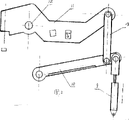
Fig. 1 is a general structure schematic diagram of the present utility model
Fig. 2 is a theory structure schematic diagram of the present utility model
Fig. 3 is the cutaway view of the utility model movable slider 11
Fig. 4 is the structural representation of the utility model material pressing device 4
Fig. 5 is the structure chart of the utility model press strip
It comprises support 1 (see figure 1) the utility model, fuselage 2, hydraulic system 3, material pressing device 4, punch member 5, electric control system 6, (see Fig. 2, Fig. 3) fuselage 2 is made up of header board 7 and back plate 8 and cushion block, single hydraulic jack 9 is fixed on the support 1, the piston rod of hydraulic jack 9 and the single face shear 10 that is contained between the front and rear panel of fuselage 2 are hinged, and the other end of single face shear 10 is hinged on the fuselage 2, and movable slide plate 11 also is housed in fuselage 2, the middle part of movable slide plate 11 is by fulcrum 12 supportings, end at movable slide plate 11 is equipped with drift 5, and the other end and connecting rod 13 are hinged, and the other end of connecting rod 13 is then hinged with shear 10, it is characterized in that on the header board 7 of fuselage 2, dead knife piece 14 being housed, movable blade piece 15 is being housed near side of fuselage header board 7 and the position relative on the movable slider 11 with dead knife piece 14.
(seeing Fig. 4, Fig. 5) shearing material pressing device 4 is made up of power part 16 and press strip 17, is provided with hypotenuse at the two ends of press strip 17.
The utility model is provided with drift 5, is mainly used in punching, and it is to be used to shear steel plate that single face shear 10 is set, and it is to be used to shear round steel and angle steel that dead knife piece 14 and movable blade piece 15 are set.
The utility model in use, if punching, the piston of hydraulic jack 9 is action upwards, rotate by shear 10 and connecting rod 133 drive activity slide plates 11, drift 5 moves downward, and realizes punching, if shear or shearing angle steel and round steel, the piston of hydraulic jack 9 is downward, drive shear 10 and movable slider 11 rotates, realize shearing, if tiltedly during the shear angle steel, angle steel is close to press strip 17 hypotenuses, compresses with briquetting again and realize shearing.
Claims (2)
1 one kinds of single hydraulic cylinder single shear punching lathes, it comprises support (1), fuselage (2), hydraulic system (3), material pressing device (4), punch member (5), electric control side part (6), fuselage (2) is made up of header board (7) and back plate (8) and cushion block, single hydraulic jack (7) is fixed on the support (1), the piston rod of hydraulic jack (9) and the single face shear (10) that is contained between the front and rear panel of fuselage (2) are hinged, the other end of single face shear (10) is hinged on the fuselage (2), movable slide plate (11) also is housed in fuselage (2), and the middle part of movable slide plate (11) is by fulcrum (12) supporting, at an end of movable slide plate (11) drift (5) is housed, the other end and connecting rod (13) are hinged, the other end of connecting rod (13) is then hinged with shear (10), it is characterized in that on the header board (7) of fuselage (2) dead knife piece (14) being housed, and on movable slider (11) is gone up near side of fuselage header board (7) and the position relative with dead knife piece (14) movable blade piece (15) is housed.
2 punching lathes according to claim 1 are characterised in that shearing material pressing device (4) is made up of power part (16) and press strip (17), is provided with hypotenuse at the two ends of press strip (17).
Priority Applications (1)
| Application Number | Priority Date | Filing Date | Title |
|---|---|---|---|
| CN 95236584 CN2283545Y (en) | 1995-04-12 | 1995-04-12 | Single hydraulic cylinder single shearing punching machine tool |
Applications Claiming Priority (1)
| Application Number | Priority Date | Filing Date | Title |
|---|---|---|---|
| CN 95236584 CN2283545Y (en) | 1995-04-12 | 1995-04-12 | Single hydraulic cylinder single shearing punching machine tool |
Publications (1)
| Publication Number | Publication Date |
|---|---|
| CN2283545Y true CN2283545Y (en) | 1998-06-10 |
Family
ID=33879545
Family Applications (1)
| Application Number | Title | Priority Date | Filing Date |
|---|---|---|---|
| CN 95236584 Expired - Fee Related CN2283545Y (en) | 1995-04-12 | 1995-04-12 | Single hydraulic cylinder single shearing punching machine tool |
Country Status (1)
| Country | Link |
|---|---|
| CN (1) | CN2283545Y (en) |
Cited By (2)
| Publication number | Priority date | Publication date | Assignee | Title |
|---|---|---|---|---|
| CN103707070A (en) * | 2013-12-25 | 2014-04-09 | 山海关船舶重工有限责任公司 | Signboard shearing and punching device |
| CN104551191A (en) * | 2014-11-27 | 2015-04-29 | 芜湖福马汽车零部件有限公司 | Large-sized thin steel plate cutter |
-
1995
- 1995-04-12 CN CN 95236584 patent/CN2283545Y/en not_active Expired - Fee Related
Cited By (2)
| Publication number | Priority date | Publication date | Assignee | Title |
|---|---|---|---|---|
| CN103707070A (en) * | 2013-12-25 | 2014-04-09 | 山海关船舶重工有限责任公司 | Signboard shearing and punching device |
| CN104551191A (en) * | 2014-11-27 | 2015-04-29 | 芜湖福马汽车零部件有限公司 | Large-sized thin steel plate cutter |
Similar Documents
| Publication | Publication Date | Title |
|---|---|---|
| CN207840260U (en) | Hydraulic gate type guillotine shear | |
| CN216181117U (en) | Die cutting die convenient to installation die cutting blade | |
| CN201389675Y (en) | Blade gap adjusting device | |
| CN212704636U (en) | Plate shearing device of metal plate stamping and shearing equipment | |
| CN207952756U (en) | A kind of simple type sheet-mill shears | |
| CN207480736U (en) | PU joint product clout automatic cutting machine structures | |
| CN2533978Y (en) | Plate shearing and bending dual-purpose machine tool | |
| CN2285712Y (en) | Transmission for press | |
| CN211304950U (en) | Horizontal shearing machine | |
| CN2841213Y (en) | Swing-type shearing-plate machine | |
| CN2339338Y (en) | Cutting-out machine for metal plate | |
| CN204867623U (en) | Closed billet shearing machine cuts material supporting mechanism | |
| CN2593934Y (en) | Dynamic bar and wire-rod rapid hydraulic cutting commutator | |
| CN220497915U (en) | Plate shearing machine for producing and processing metal box body of distribution box | |
| CN212865399U (en) | A cutting device for nylon and cotton production | |
| CN2228815Y (en) | Bar stock clipping machine | |
| CN2160489Y (en) | Hydraulic blank shearing machine | |
| CN218362351U (en) | Novel hydraulic plate shearing machine | |
| CN2231588Y (en) | Vibration shearing machine | |
| CN221620939U (en) | A steel precision shearing device | |
| CN220943428U (en) | Sliding shearing machine | |
| CN2233806Y (en) | Positioning device for bar cutting machine | |
| CN214352621U (en) | Die cutting device of full-automatic die cutting machine | |
| CN221066577U (en) | Electric push rod U plastic switch strip cutting mechanism | |
| CN219926533U (en) | Punching device for processing graphite flake |
Legal Events
| Date | Code | Title | Description |
|---|---|---|---|
| C14 | Grant of patent or utility model | ||
| GR01 | Patent grant | ||
| C19 | Lapse of patent right due to non-payment of the annual fee | ||
| CF01 | Termination of patent right due to non-payment of annual fee |