CN2213685Y - Roll film fixing jig - Google Patents
Roll film fixing jig Download PDFInfo
- Publication number
- CN2213685Y CN2213685Y CN 94214769 CN94214769U CN2213685Y CN 2213685 Y CN2213685 Y CN 2213685Y CN 94214769 CN94214769 CN 94214769 CN 94214769 U CN94214769 U CN 94214769U CN 2213685 Y CN2213685 Y CN 2213685Y
- Authority
- CN
- China
- Prior art keywords
- screw rod
- sleeve
- chuck
- tapered
- screw
- Prior art date
- Legal status (The legal status is an assumption and is not a legal conclusion. Google has not performed a legal analysis and makes no representation as to the accuracy of the status listed.)
- Expired - Fee Related
Links
- 229920006280 packaging film Polymers 0.000 abstract description 25
- 239000012785 packaging film Substances 0.000 abstract description 25
- 230000002457 bidirectional effect Effects 0.000 abstract description 2
- 208000004350 Strabismus Diseases 0.000 abstract 1
- 238000012856 packing Methods 0.000 description 7
- 230000009471 action Effects 0.000 description 6
- 230000000694 effects Effects 0.000 description 5
- 239000012528 membrane Substances 0.000 description 5
- 238000010586 diagram Methods 0.000 description 3
- 238000004519 manufacturing process Methods 0.000 description 3
- NJPPVKZQTLUDBO-UHFFFAOYSA-N novaluron Chemical compound C1=C(Cl)C(OC(F)(F)C(OC(F)(F)F)F)=CC=C1NC(=O)NC(=O)C1=C(F)C=CC=C1F NJPPVKZQTLUDBO-UHFFFAOYSA-N 0.000 description 3
- 238000010276 construction Methods 0.000 description 2
- 235000013305 food Nutrition 0.000 description 2
- 238000009434 installation Methods 0.000 description 2
- 238000000465 moulding Methods 0.000 description 2
- 238000000354 decomposition reaction Methods 0.000 description 1
- 239000003292 glue Substances 0.000 description 1
- 230000006872 improvement Effects 0.000 description 1
- 230000007246 mechanism Effects 0.000 description 1
- 238000000034 method Methods 0.000 description 1
- 238000004806 packaging method and process Methods 0.000 description 1
- 235000021485 packed food Nutrition 0.000 description 1
- 230000008569 process Effects 0.000 description 1
- KNVAYBMMCPLDOZ-UHFFFAOYSA-N propan-2-yl 12-hydroxyoctadecanoate Chemical compound CCCCCCC(O)CCCCCCCCCCC(=O)OC(C)C KNVAYBMMCPLDOZ-UHFFFAOYSA-N 0.000 description 1
- 238000000926 separation method Methods 0.000 description 1
- 230000001360 synchronised effect Effects 0.000 description 1
Images


Landscapes
- Basic Packing Technique (AREA)
Abstract
The utility model relates to a roll film mounting fixture, it is that both sides are the spiral shell respectively and are established a toper chuck on a bidirectional screw, one of them side is a fixed toper chuck, can be along with the rotation of screw rod and the back-and-forth movement, but the toper chuck of the other side then includes a toper slide bar and the chuck that can elastically contract, this two toper chucks locate on the screw rod after arrange a sleeve in again, and make its conical clamp foot expose outside the sleeve and feasible centre gripping packaging film's utility, and can reach the automatic centering position of adjusting and make the packaging film of centre gripping not squint by rotatory adjustment screw rod.
Description
The utility model relates to a kind of novel designs of web-like film stationary fixture, the effect that it reached makes wrapping machine or other use such web-like film to make packing timber packaging film cylinder mechanically all can be by design of the present utility model, and center capable of automatic aligning clamping makes not off normal, and the dismounting of packaging film cylinder all can reach convenient easy purpose.
The use of wrapping machine is the topmost processing equipment that present packed food is machined to commodity at last, and it makes commodity after the packaging film quantitative package and can be used as the appraisal of commodity value and separate, and is the indispensable a kind of industrial machine of a food industry.
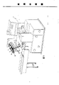
Yet, structure about its body of wrapping machine, it mainly is external form as shown in Figure 1, wherein existing anchor clamps in order to clamping packaging film cylinder are as shown in Figure 6 moulding construction then partly, it mainly is respectively to be nested with a conical chuck 2a in clamping loop bar 1a both sides, this two conical chuck 2a can arbitrarily be slided and place on the loop bar 1a, and mat one lock screw rod 21a gives stationary positioned.Adjust the relative position of two conical chuck 2a, and be nested with packaging film cylinder 3a, make two conical chuck 2a hold out against packaging film cylinder 3a mutually, with lock screw rod 21a conical chuck 2a is fixed again, send feeding so that packaging film cylinder 3a can roll up between the two.Yet, when sending, volume can be fixed in the operation bed platform middle position of body for the glued membrane that makes packaging film cylinder 3a, can't pack with the deviation that prevents glued membrane, must go up prior to loop bar 1a and measure correct midline position with chi 4a, it is wide and by the center that places loop bar 1a to cooperate Different Package membrane cylinder 3a to have different tubes again, and then the conical chuck 2a ejection of both sides is fixed in packaging film cylinder 3a both sides.But this practice of measuring center line is when reality is implemented, and not only is difficult for correctly measuring its center line, and because the time-consuming long wrapping machine overall operation increase in man-hour that makes of the process institute that its adjustment aligns, the indirect production capacity that influences.And the conical chuck 2a that is positioned at packaging film cylinder 3a both sides also may make conical chuck 2a produce the skew effect in lock screw rod 21a locking, and causes the correctness of its centering bad.Moreover, when changing the outfit packaging film cylinder 3a, packaging film cylinder 3a is set in loop bar 1a because essential first conical chuck 2a with a side is removed again, extremely not convenient on it changes the outfit, and still treat further improvement; Utilize the mechanical device of similar drum packing timber as for other, be not located at the center volume and send because its design also has more novel structure, therefore, also difficulty reaches requirement on practicality.
Main purpose of the present utility model is: a kind of web-like film stationary fixture is provided, its mat both sides are provided with on the screw rod of reverse thread, both sides respectively are provided with a conical chuck, wherein its taper pinch of a side chuck is to be a fixed form, but side chuck pinch then contracts in the elasticity in addition, but and place a taper slide bar in the chuck that in this elasticity, contracts, with control its elastomeric expansion and in contract, rotary screw can make the both sides conical chuck move synchronously or separate to both sides, and reach automatically effect to median line, and above-mentioned assembling mechanism outside in addition a sheathed sleeve packaging film cylinder must be nested with wherein and the packaging film cylinder is made in midline position in the pinch that mat both sides conical chuck protrudes out top.
A purpose more of the present utility model is: a kind of web-like film stationary fixture is provided, but it is provided with the conical chuck of elastic dilatation owing to a side on the screw rod, slide bar wherein can be adjusted the expansion of its pinch, can remove easily or install for the packaging film cylinder when time in the pinch retraction sleeve, and but actv. reduces the time of wrapping machine integral installation and adjustment, increases production efficiency.
The purpose of this utility model is achieved through the following technical solutions, a kind of web-like film stationary fixture, it includes both sides and is provided with the screw rod of reverse thread each other, and the conical chuck of being located at both sides on the screw rod, with screw rod and conical chuck fabricate block are placed in sleeve, wherein have a plurality of machine made taper pinches on it at the conical chuck of screw rod one side, chuck central authorities then are a hollow screw, but be located at other conical chuck of side of screw rod and then have the pinch that contracts in the elasticity, make the turn screw rod can make the close synchronously or separation of two conical chucks to the midline position of screw rod, and the pinch position with respect to two conical chucks is provided with long and narrow hole on the sleeve, can stretch for the pinch of two conical chucks, then do not link to each other mutually between the long and narrow hole of sleeve both sides, other respectively is nested with a bearing respectively at the two ends of sleeve inner screw and is fixedly arranged on the sleeve, and an end is set a handle therein, can make screw rod produce turn and then makes slippage about two conical chucks produce by the rotation of handle.
Aforementioned web-like film stationary fixture, but be positioned at the conical chuck that screw rod one side has the elastic dilatation pinch, it comprises by a slide bar and a pinch seat and being formed, wherein the front end of slide bar is a bullet, thereafter extending a straight-bar can be set in the pinch seat and set firmly a snap ring in its back-end, and the central authorities of slide bar but to be a hollow screw spiral shell be located on the screw rod, but the pinch that contracts in a plurality of elasticity is arranged around then mat one spring is hubbed on the pedestal of pinch seat, the side in addition of pedestal then is equipped with a packing packing ring.
The utility model has the advantages that it has automatic effect to median line, and can reduce the time of wrapping machine integral installation and adjustment effectively, increase production efficiency.
Further specify architectural feature of the present utility model and purpose below in conjunction with accompanying drawing.
Brief Description Of Drawings:
Fig. 1 is stereoscopic figure of the present utility model.
Fig. 2 is system decomposition figure of the present utility model.
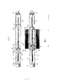
Fig. 3 is a structure action diagram of the present utility model.
Fig. 4 is an enforcement action diagram of the present utility model.
Fig. 5 is that of the present utility model another implemented action diagram.
Fig. 6 is for having the section plan in order to the anchor clamps part moulding construction of clamping packaging film cylinder now.
At first, please referring to shown in Figure 1, web-like film stationary fixture provided by the utility model, mainly be on wrapping machine 1, to hold packaging film cylinder 2 and location in order to cover, the anchor clamps 3 that send feeding that package glue film carries out food contents and bagging and packaging supervisor etc. with volume as an example, yet its still applicable to other associated class like industrial machine, therefore its extensive applicability is arranged, yet because this type of machinery all need make packaging film cylinder 2 be positioned the body middle position, just can make glued membrane not produce the bias effect package handling, therefore need a kind of tool automatically to RC novel jig Design not influence its operation.
Please continue referring to shown in Figure 2, these anchor clamps mainly are to have two conical chucks 32,33 that reverse thread design-calculated screw rod 31 each other and screw rod 31 both sides spiral shells are put by both sides, and screw rod 31 conical chucks 32 that are nested with after the combination are combined in the interior sleeve 34 of doing the slippage adjustment; Wherein, the conical chuck 32 that is positioned at screw rod 31 1 sides has machine made taper pinch 321, and the mesopore of conical chuck is a tapped bore, can be bolted on the screw rod 31 sway with the turn of screw rod 31; Yet, be positioned at screw rod 31 conical chuck 33 of side in addition, then form by a pinch seat 331 and a slide bar 332 cross-under, pinch seat 331 is provided with four pinches 334 by spring 333 pivot joints, thereby can make pinch 334 do the action of contracting in elastomeric, in addition on the pedestal of pinch seat 331 then ring establish a packing packing ring 335, adjust conical chuck 33 and on screw rod 31, move that more shape is certain and have to make; And slide bar 332 its central authorities are provided with screw, its front end and be a bullet, and the straight-bar of Yan Shening can wear pinch seat 334 and combine with a snap ring 336 at other end thereafter, makes pinch seat 331 be limited to slide bar 332 and 336 slippages actions of snap ring; Secondly, sleeve 34 is a hollow tube, be provided with the long and narrow hole 341 that can wear dew for two conical chucks 32 and 33 pinches 321,334 on the surface of body, and 341 of body both sides long and narrow holes do not link to each other so that two conical chucks 32 and 33 each in a spacing, do left and right sides slippage action.
In addition, at the two ends of sleeve 34 inner screws 31, then be separately installed with a bearing 35 on sleeve pipe 34, and be embedded with a handle 36, make and rotate handle 36 and can make screw rod 31 produce turns at a side screw rod 31.
Please referring again to shown in Figure 3, because two conical chucks 32,33 spiral shell respectively are located at screw rod 31 both sides with bidirectional helical, therefore, when screw rod 31 is subjected to turn because of handle 36, then two conical chucks 32 promptly produce synchronous relatively near or disengaging movement, the pinch 321,334 of conical chuck 32,33 then is restricted to the slippage about doing in the long and narrow hole 341 of sleeve 34.
At last, please cooperate simultaneously referring to Fig. 4 and shown in Figure 5, when packing membrane cylinder 2 is installed, but slide bar 332 bullets that earlier handle 36 clickwises made screw rod 31 1 side conical chucks 33 are partly gradually away from open pinch 334 parts of pinch seat 331 elasticity, and making pinch 334 gradually in the retraction sleeve 34, the open end that then makes packaging film cylinder 2 derive from sleeve 34 is separated and is changed the outfit; And the packaging film cylinder 2 after changing the outfit is positioned at two conical chucks 32,33, at this moment, again with handle 36 inhour rotations, can make two conical chucks 32,33 is close each other, owing to mainly be moving about slide bar 332 produces in the conical chuck 33, therefore, when bullet can make pinch 334 elastic dilatation gradually during near pinch 334, when pinch 334 abuts against root edge in bullet, it then is the maximum range that pinch 334 enlarges, at this moment, if both sides conical chuck 32,33 still fail to reach the purpose of clamping packaging film cylinder 2, then can continue turn screw rod 31 and make two conical chucks 32,33 is partly approaching to screw rod 31 center lines gradually, and wherein, slide bar 332 root edges of conical chuck 33 can push that pinch seat 331 moves to right and till be held on packaging film cylinder 2, otherwise,, screw rod 31 is just being changeed makes in the pinch 334 and contract if wide excessive because of the tube of packaging film cylinder 2, slide bar 332 then moves to left to make snap ring 336 rely on pinch seat 331 and drive pinch seat 331 simultaneously and moves to left, to increase two conical chucks 32,33 width.
Claims (2)
Priority Applications (1)
| Application Number | Priority Date | Filing Date | Title |
|---|---|---|---|
| CN 94214769 CN2213685Y (en) | 1994-06-14 | 1994-06-14 | Roll film fixing jig |
Applications Claiming Priority (1)
| Application Number | Priority Date | Filing Date | Title |
|---|---|---|---|
| CN 94214769 CN2213685Y (en) | 1994-06-14 | 1994-06-14 | Roll film fixing jig |
Publications (1)
| Publication Number | Publication Date |
|---|---|
| CN2213685Y true CN2213685Y (en) | 1995-11-29 |
Family
ID=33830948
Family Applications (1)
| Application Number | Title | Priority Date | Filing Date |
|---|---|---|---|
| CN 94214769 Expired - Fee Related CN2213685Y (en) | 1994-06-14 | 1994-06-14 | Roll film fixing jig |
Country Status (1)
| Country | Link |
|---|---|
| CN (1) | CN2213685Y (en) |
Cited By (2)
| Publication number | Priority date | Publication date | Assignee | Title |
|---|---|---|---|---|
| CN101137543B (en) * | 2005-02-10 | 2010-08-25 | 奥伊M.赫洛伊拉私人公司 | Method and apparatus for forming a top film sheet from a film sheet |
| CN101863325A (en) * | 2010-06-23 | 2010-10-20 | 铜陵市松马食品包装机械制造有限责任公司 | Bearing of belt forming apparatus of bag packaging machine |
-
1994
- 1994-06-14 CN CN 94214769 patent/CN2213685Y/en not_active Expired - Fee Related
Cited By (2)
| Publication number | Priority date | Publication date | Assignee | Title |
|---|---|---|---|---|
| CN101137543B (en) * | 2005-02-10 | 2010-08-25 | 奥伊M.赫洛伊拉私人公司 | Method and apparatus for forming a top film sheet from a film sheet |
| CN101863325A (en) * | 2010-06-23 | 2010-10-20 | 铜陵市松马食品包装机械制造有限责任公司 | Bearing of belt forming apparatus of bag packaging machine |
Similar Documents
| Publication | Publication Date | Title |
|---|---|---|
| US20010024044A1 (en) | Work chucking/inserting apparatus and assembling unit | |
| CN201729522U (en) | Compact belt hanging machine | |
| CN108941797A (en) | A kind of high-precision intelligent tapping machine | |
| CN116000616A (en) | Valve rod valve core coaxiality corrector | |
| CN109015554B (en) | Working method of machining platform for automobile part production | |
| CN201485094U (en) | Belt hanging machine | |
| CA3234707A1 (en) | Log cutting saw with automatic blade changer and method of using same | |
| CN108571919B (en) | Full-elastic combination device | |
| CN207013479U (en) | A kind of unwinding device for automatic stamping equipment | |
| CN104128707A (en) | Clamp head fixed type optical fiber assembly clamp for coupling and welding of coaxial type photoelectric device | |
| CN108356589A (en) | Steel tube surface sizing drilling tool holder | |
| CN207358602U (en) | A kind of fixture for numerical control machining center | |
| CN212349998U (en) | Hand-held type bending device | |
| CN207824465U (en) | The clamp for machining with taper hole workpiece is used on a kind of numerically-controlled machine tool | |
| CN115265306B (en) | A clamp-and-jaw integrated testing platform | |
| CN206764347U (en) | A kind of automation fixture | |
| CN212599747U (en) | Be applied to air chuck's synchronization disc and rotator subassembly | |
| CN212599303U (en) | Pipeline cutting device that petrochemical industry installation engineering used | |
| CN209774131U (en) | Pneumatic connecting rod oscillating centering mechanism | |
| CN209902797U (en) | Carrier roller detection tool | |
| CN221216707U (en) | Shaftless clamping device | |
| JPS602419A (en) | Packer | |
| CN223617682U (en) | Hydrogen storage bottle tube blank performance detection device | |
| CN116372252B (en) | Hose cutting device | |
| CN207808642U (en) | A wrapping machine |
Legal Events
| Date | Code | Title | Description |
|---|---|---|---|
| C14 | Grant of patent or utility model | ||
| GR01 | Patent grant | ||
| C19 | Lapse of patent right due to non-payment of the annual fee | ||
| CF01 | Termination of patent right due to non-payment of annual fee |