CN219352249U - Electric control box, electric control components and air conditioner - Google Patents
Electric control box, electric control components and air conditioner Download PDFInfo
- Publication number
- CN219352249U CN219352249U CN202320796895.9U CN202320796895U CN219352249U CN 219352249 U CN219352249 U CN 219352249U CN 202320796895 U CN202320796895 U CN 202320796895U CN 219352249 U CN219352249 U CN 219352249U
- Authority
- CN
- China
- Prior art keywords
- heat dissipation
- opening
- electronic control
- box body
- control box
- Prior art date
- Legal status (The legal status is an assumption and is not a legal conclusion. Google has not performed a legal analysis and makes no representation as to the accuracy of the status listed.)
- Active
Links
Images




Landscapes
- Cooling Or The Like Of Electrical Apparatus (AREA)
Abstract
Description
技术领域technical field
本公开涉及空调技术的领域,尤其涉及电控盒、电控组件和空调。The present disclosure relates to the field of air conditioner technology, and in particular to an electric control box, an electric control assembly and an air conditioner.
背景技术Background technique
空调室外机分为风机腔和压缩机腔,中间由中隔板隔开。轴流风叶位于风机腔,其可将空气吹出至环境中。电控组件位于压缩机腔,电控组件包括电控盒、设置在电控盒内的主控板等,电控盒安装在中隔板上,主控板起到控制风叶电机、压缩机等运作的作用。The outdoor unit of the air conditioner is divided into a fan chamber and a compressor chamber, which are separated by a middle partition. Axial flow blades are located in the fan cavity, which blows air out into the environment. The electric control component is located in the compressor cavity, and the electric control component includes the electric control box, the main control board installed in the electric control box, etc. Wait for the function of operation.
由于位于压缩机侧的主控板上有许多的电子元器件,因此电控组件需要具有防虫防水的要求,同时由于主控板上功率模块的温升问题,因此需要提高电控盒的散热能力,以改善功率模块的工作性能。Since there are many electronic components on the main control board on the side of the compressor, the electronic control components need to be insect-proof and waterproof. At the same time, due to the temperature rise of the power module on the main control board, it is necessary to improve the heat dissipation capacity of the electric control box , to improve the working performance of the power module.
实用新型内容Utility model content
本公开提供一种电控盒、电控组件和空调,能够在满足电控盒散热的同时,具有防水和防虫的效果。The disclosure provides an electric control box, an electric control component and an air conditioner, which can satisfy the heat dissipation requirements of the electric control box and have the effect of waterproofing and preventing insects.
根据本公开实施例的第一方面,提供一种电控盒,包括盒体和遮挡件,所述盒体上设置有用于供散热器穿过的安装口,所述盒体包括靠近所述安装口设置的第一腔壁,所述第一腔壁上设置有第一散热口,所述盒体上设置有第一开口,所述第一开口用于配合所述第一散热口出模成型,所述遮挡件设置于所述盒体并用于封堵所述第一开口。According to the first aspect of the embodiments of the present disclosure, there is provided an electric control box, including a box body and a shield, the box body is provided with an installation opening for the radiator to pass through, and the box body includes a The first cavity wall provided with the mouth, the first cavity wall is provided with a first heat dissipation port, the box body is provided with a first opening, and the first opening is used to cooperate with the first heat dissipation port for molding , the blocking member is disposed on the box body and used to block the first opening.
可选地,所述电控盒还包括挡板,所述挡板设置于所述盒体并正对所述第一散热口设置,所述挡板与所述第一腔壁间隔设置并形成第一空间,所述第一空间贯穿所述盒体的一侧以形成所述第一开口,所述挡板上设置有第二散热口,所述第一散热口和所述第二散热口均与所述第一空间连通。Optionally, the electric control box further includes a baffle, the baffle is arranged on the box body and facing the first heat dissipation port, the baffle is spaced apart from the first cavity wall and forms a The first space, the first space runs through one side of the box body to form the first opening, the baffle is provided with a second heat dissipation port, the first heat dissipation port and the second heat dissipation port All communicate with the first space.
可选地,所述第二散热口与所述第一散热口错位布置。Optionally, the second heat dissipation opening and the first heat dissipation opening are arranged in a dislocation manner.
可选地,所述第一散热口沿第一方向延伸且沿与所述第一方向相交的第二方向间隔排布为多个,多个所述第一散热口在所述第一方向上高于所述第二散热口。Optionally, the first heat dissipation openings extend along the first direction and are arranged in a plurality at intervals along the second direction intersecting the first direction, and the plurality of first heat dissipation openings are arranged in the first direction higher than the second heat dissipation port.
可选地,所述盒体包括底壁,所述第二散热口设置在所述挡板靠近所述底壁的一侧,以使得所述挡板与所述底壁之间形成有间隙。Optionally, the box body includes a bottom wall, and the second heat dissipation port is disposed on a side of the baffle close to the bottom wall, so that a gap is formed between the baffle and the bottom wall.
可选地,所述遮挡件固定连接于所述底壁并封堵所述第一开口。Optionally, the blocking member is fixedly connected to the bottom wall and blocks the first opening.
可选地,所述电控盒还包括封板,所述封板连接所述挡板和所述第一腔壁并且与所述第一开口相对布置。Optionally, the electric control box further includes a sealing plate, the sealing plate connects the baffle plate and the first cavity wall and is arranged opposite to the first opening.
可选地,所述第一腔壁在所述第一散热口于第二方向上的两侧分别设置有第三散热口。Optionally, the first cavity wall is respectively provided with third cooling ports on both sides of the first cooling port in the second direction.
可选地,所述盒体还包括两个第二腔壁,两个所述第二腔壁分别位于所述挡板的两侧并分别正对于对应的所述第三散热口设置,两个所述第二腔壁均与所述第一腔壁间隔设置并分别形成两个第二空间,两个所述第二腔壁上均设置有第四散热口,所述第三散热口与所述第四散热口均与对应的所述第二空间连通。Optionally, the box body further includes two second cavity walls, the two second cavity walls are respectively located on both sides of the baffle plate and are respectively arranged opposite to the corresponding third heat dissipation openings, and the two second cavity walls The second chamber walls are spaced apart from the first chamber walls to form two second spaces respectively, the two second chamber walls are provided with fourth heat dissipation ports, and the third heat dissipation ports are connected to the second chamber walls. Each of the fourth heat dissipation openings communicates with the corresponding second space.
可选地,所述挡板与两侧的所述第二腔壁一体连接。Optionally, the baffle is integrally connected with the second cavity walls on both sides.
可选地,两个所述第二空间均贯穿所述盒体的一侧并分别在所盒体上形成两个第二开口,两个所述第二开口分别位于所述第一开口的两侧。Optionally, both of the two second spaces pass through one side of the box body and form two second openings on the box body, and the two second openings are respectively located on two sides of the first opening. side.
可选地,所述盒体还包括两个遮挡壁,两个所述遮挡壁与对应的所述第二开口相对布置并且分别连接所述第一腔壁与对应的所述第二腔壁。Optionally, the box body further includes two shielding walls, the two shielding walls are arranged opposite to the corresponding second opening and respectively connect the first cavity wall and the corresponding second cavity wall.
可选地,所述电控盒还包括用于封闭所述第一空间顶部的封板,所述封板位于两个所述遮挡壁之间并与两侧的所述遮挡壁一体连接。Optionally, the electric control box further includes a sealing plate for closing the top of the first space, the sealing plate is located between the two shielding walls and integrally connected with the shielding walls on both sides.
可选地,所述电控盒还包括两个隔板,所述第一空间与两侧的所述第二空间之间均设置所述隔板进行分隔。Optionally, the electric control box further includes two partitions, and the first space is separated from the second spaces on both sides by the partitions.
可选地,至少一个所述隔板上设置有所述散热槽,所述散热槽用于连通所述第一空间和所述第二空间。Optionally, at least one of the separators is provided with the heat dissipation groove, and the heat dissipation groove is used to communicate with the first space and the second space.
根据本公开实施例的第二方面,提供一种电控组件,包括主控板和上述电控盒,所述主控板安装在所述电控盒内。According to a second aspect of the embodiments of the present disclosure, there is provided an electric control assembly, including a main control board and the above electric control box, the main control board is installed in the electric control box.
可选地,所述电控组件还包括盒盖,所述盒盖安装于所述电控盒的盒体并与所述盒体封装所述主控板。Optionally, the electric control assembly further includes a box cover, and the box cover is installed on the box body of the electric control box and seals the main control board with the box body.
根据本公开实施例的第三方面,提供一种空调,所述空调包括空调室外机和室内机,所述空调室外机包括中隔板和上述电控组件,所述电控盒固定安装在所述中隔板上。According to a third aspect of the embodiments of the present disclosure, there is provided an air conditioner, the air conditioner includes an air conditioner outdoor unit and an indoor unit, the air conditioner outdoor unit includes a middle partition and the above-mentioned electric control assembly, and the electric control box is fixedly installed on the on the middle partition.
本公开的实施例提供的技术方案可以包括以下有益效果:在靠近安装口的第一腔壁上设置第一散热口,盒体内的热量从第一散热口处散出并流向安装口内的散热器处,然后在风机腔内风叶的配合下实现散热。为了能够在设置第一散热口后使电控盒顺利出模,盒体上设置了配合第一散热口出模成型的第一开口,由于电控盒安装在中隔板上,所以第一开口有暴露在风机腔一侧的可能性,因此在盒体上设置遮挡件对第一开口进行封堵,降低了风机腔一侧的水和蚊虫进入到盒体内的可能性。因此,采用本公开的电控盒,能够在满足电控盒散热的同时,具有防水和防虫的效果。The technical solution provided by the embodiments of the present disclosure may include the following beneficial effects: a first heat dissipation port is provided on the first cavity wall close to the installation port, and the heat in the box dissipates from the first heat dissipation port and flows to the radiator in the installation port place, and then realize heat dissipation with the cooperation of the fan blades in the fan cavity. In order to enable the electric control box to be released from the mold smoothly after the first heat dissipation port is installed, a first opening is set on the box body to cooperate with the first heat dissipation port. Since the electric control box is installed on the middle partition, the first opening There is a possibility of being exposed on one side of the fan cavity, so a shield is provided on the box body to block the first opening, which reduces the possibility of water and mosquitoes on the side of the fan cavity entering the box body. Therefore, adopting the electric control box of the present disclosure can meet the heat dissipation requirements of the electric control box and at the same time have the effect of waterproofing and preventing insects.
应当理解的是,以上的一般描述和后文的细节描述仅是示例性和解释性的,并不能限制本公开。It is to be understood that both the foregoing general description and the following detailed description are exemplary and explanatory only and are not restrictive of the present disclosure.
附图说明Description of drawings
此处的附图被并入说明书中并构成本说明书的一部分,示出了符合本公开的实施例,并与说明书一起用于解释本公开的原理。The accompanying drawings, which are incorporated in and constitute a part of this specification, illustrate embodiments consistent with the disclosure and together with the description serve to explain the principles of the disclosure.
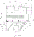
图1是根据一示例性实施例示出的电控盒的整体结构示意图;Fig. 1 is a schematic diagram of the overall structure of an electric control box according to an exemplary embodiment;
图2是根据一示例性实施例示出的电控盒的遮挡件的结构示意图;Fig. 2 is a schematic structural view of a shielding member of an electric control box according to an exemplary embodiment;
图3是根据一示例性实施例示出的电控盒的第一开口的结构示意图;Fig. 3 is a schematic structural view of the first opening of the electric control box according to an exemplary embodiment;
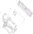
图4是根据一示例性实施例示出的电控组件的爆炸结构示意图;Fig. 4 is a schematic diagram showing an exploded structure of an electric control assembly according to an exemplary embodiment;
图5是根据一示例性实施例示出的空调室外机的中隔板的结构示意图;Fig. 5 is a schematic structural view of a middle partition of an outdoor unit of an air conditioner according to an exemplary embodiment;
图6是根据一示例性实施例示出的空调室外机的局部结构示意图。Fig. 6 is a schematic diagram of a partial structure of an outdoor unit of an air conditioner according to an exemplary embodiment.
附图说明Description of drawings
1-盒体;11-安装口;12-第一腔壁;121-第一散热口;122-第三散热口;13-第一开口;14-底壁;15-第二腔壁;151-第二空间;152-第四散热口;16-第二开口;17-遮挡壁;2-遮挡件;3-挡板;31-第一空间;32-第二散热口;4-封板;5-隔板;51-散热槽;6-主控板;7-盒盖;8-中隔板;81-风机腔;82-压缩机腔;83-钣金件。1-Box body; 11-Installation port; 12-First chamber wall; 121-First heat dissipation port; 122-Third heat dissipation port; 13-First opening; 14-Bottom wall; 15-Second chamber wall; 151 -Second space; 152-fourth cooling vent; 16-second opening; 17-shielding wall; 2-shielding member; 3-baffle; 31-first space; ;
具体实施方式Detailed ways
以下结合附图对本公开的具体实施方式进行详细说明。应当理解的是,此处所描述的具体实施方式仅用于说明和解释本公开,并不用于限制本公开。Specific embodiments of the present disclosure will be described in detail below in conjunction with the accompanying drawings. It should be understood that the specific embodiments described here are only used to illustrate and explain the present disclosure, and are not intended to limit the present disclosure.
在本公开中,在未作相反说明的情况下,“内、外”是相对于对应部件自身轮廓而言的“内、外”,“远、近”是指相较于对比参考物的“远、近”。此外,本公开所使用的术语如“第一”、“第二”等是为了区分一个要素和另一个要素,不具有顺序性和重要性。在下面的描述中,当涉及到附图时,除非另有解释,不同的附图中相同的附图标记表示相同或相似的要素。上述定义仅用于解释和说明本公开,不应当理解为对本公开的限制。In the present disclosure, unless stated to the contrary, "inner and outer" refer to "inner and outer" relative to the contour of the corresponding component itself, and "far and near" refer to the " far and near". In addition, terms such as "first", "second" and the like used in the present disclosure are used to distinguish one element from another, and do not have sequence or importance. In the following description, when referring to the drawings, the same reference numerals in different drawings denote the same or similar elements unless otherwise explained. The above definitions are only used to explain and describe the present disclosure, and should not be construed as limiting the present disclosure.
根据本公开的具体实施方式,参照图1至图3中所示,本公开提供一种电控盒,包括盒体1和遮挡件2,盒体1上设置有用于供散热器穿过的安装口11,盒体1包括靠近安装口11设置的第一腔壁12,第一腔壁12上设置有第一散热口121,盒体1上设置有第一开口13,第一开口13用于配合第一散热口121出模成型,遮挡件2设置于盒体1并用于封堵第一开口13。According to a specific embodiment of the present disclosure, as shown in FIGS. 1 to 3 , the present disclosure provides an electric control box, which includes a
通过上述技术方案,在靠近安装口11的第一腔壁12上设置第一散热口121,盒体1内的热量从第一散热口121处散出并流向安装口11处的散热器,然后在风机腔81内风叶的配合下实现散热。为了能够在设置第一散热口121后使电控盒顺利出模,盒体1上设置了配合第一散热口121出模成型的第一开口13,由于电控盒安装在中隔板8上,所以第一开口13有暴露在风机腔81一侧的可能性,因此在盒体1上设置遮挡件2对第一开口13进行封堵,降低了风机腔81一侧的水和蚊虫进入到盒体1内的可能性。因此,采用本公开的电控盒,能够在满足散热要求的同时,具有防水和防虫的效果。Through the above-mentioned technical solution, a first
其中,参照图1至图3中所示,当电控盒安装在中隔板8上后,散热器位于风机腔81一侧,也就是电控盒的部分结构(包括安装口11)位于风机腔81一侧,另一部分结构位于压缩机腔82一侧。第一腔壁12为盒体1靠近安装口11的侧壁,也就是盒体1朝向散热器的壁,第一腔壁12可以是直板状的腔壁,也可以是凹凸不平的腔壁,还可以是弯折的或多段连接形成的腔壁,本公开对此不作具体限制。由于设置第一散热口121,因此盒体1上必须设置便于出模的第一开口13,第一开口13的大小根据第一散热口121的设置情况进行确定。Wherein, as shown in Fig. 1 to Fig. 3, when the electric control box is installed on the
为了降低水进入盒体1内进而损坏主控板6的可能性,在本公开提供的一种实施方式中,参照图1至图3中所示,电控盒还包括挡板3,挡板3设置于盒体1并正对第一散热口121设置,挡板3与第一腔壁12间隔设置并形成第一空间31,第一空间31贯穿盒体1的一侧以形成第一开口13,挡板3上设置有第二散热口32,第一散热口121和第二散热口32均与第一空间31连通。In order to reduce the possibility of water entering the
通过上述技术方案,由于风机腔81的风叶在转动时有将水甩向第一腔壁12的可能性,而被甩向第一腔壁12的水若穿过第一散热口121进入盒体1内会沾湿主控板6,导致主控板6受损,因此设置开设第二散热口32的挡板3,即不影响盒体1的散热,也能够对甩向盒体1内的水进行阻拦。需要说明的是,参照图1和图2中所示,挡板3可以后期安装固定在盒体1上,也可以与盒体1一体连接(也就是出模一体成型)。Through the above-mentioned technical scheme, since the fan blades of the
当盒体1外的水穿过第一散热口121后,为了避免水再穿过第二散热口32进入盒体1,在本公开提供的一种实施方式中,参照图1和图2中所示,第二散热口32与第一散热口121错位布置。需要说明的是,所述的错位布置是指第一散热口121在挡板3上的投影与第二散热口32不重合,同样的,第二散热口32在第一腔壁12上的投影也与第一散热口121不重合。After the water outside the
在其他实施方式中,第一散热口121可以设置一个,在本公开提供的一种实施方式中,参照图1和图2中所示,第一散热口121沿第一方向延伸且沿与第一方向相交的第二方向间隔排布为多个,多个第一散热口121在第一方向上高于第二散热口32。通过上述设计方式,设置多个第一散热口121能够使散热效果更好,且第一散热口121高于第二散热口32更符合热量流动的路径,实现高效散热。In other embodiments, one first
需要说明的是,参照图1和图2中所示,第一方向可以是电控盒安装在中隔板8上后的竖直方向,也可以是电控盒安装在中隔板8上后的倾斜方向,本公开附图以第一方向为电控盒安装后的竖直方向为例进行呈现。第二方向可以与第一方向垂直,在这种情况下,第二方向为电控盒安装后的水平方向,在其他实施方式中,第二方向也可以和第一方向不垂直的相交。It should be noted that, referring to Fig. 1 and Fig. 2, the first direction may be the vertical direction after the electric control box is installed on the
其中,参照图1和图2中所示,第一散热口121可以是长条状并沿第一方向延伸,在附图示出的实施例中,第一腔壁12沿第二方向延伸,也就是多个第一散热口121可以沿第一腔壁12的长度方向排布。在其他实施方式中,第一腔壁12的长度方向上可以全部设置第一散热口121,在本公开提供的一种实施方式中,可以仅第一腔壁12长度方向的中部位置处设置第一散热口121,在该种情况下,第一开口13也就对应设置在盒体1于第二方向上的中部位置处。在其他实施方式中,第一散热口121还可以沿第二方向延伸并且多个第一散热口121沿第一方向排布。Wherein, as shown in FIG. 1 and FIG. 2, the
在本公开提供的一种实施方式中,参照图1中所示,盒体1包括底壁14,第二散热口32设置在挡板3靠近底壁14的一侧,以使得挡板3与底壁14之间形成有间隙。其中,热量从开设第二散热口32后的挡板3底部与底壁14之间进入第一空间31后通过第一散热口121散出。在其他实施方式中,第二散热口32也可以设置多个并沿第二方向或第一方向排布。In one embodiment provided by the present disclosure, as shown in FIG. A gap is formed between the
需要说明的是,第一开口13位于盒体1设置底壁14的一侧,为了便于固定遮挡件2。在本公开提供的一种实施方式中,参照图2中所示,遮挡件2固定连接于底壁14并封堵第一开口13。通过上述设计方式,即便于对遮挡件2进行固定,也便于对第一开口13进行遮挡。其中,遮挡件2可以构造为金属片且呈方片状,遮挡件2也可以为适应第一开口13的形状而构造为其他形状或结构,遮挡件2粘接在底壁14上并封堵第一开口13。在本公开提供的一种实施方式中,底壁14上粘接遮挡件2的位置可以构造为凹陷的结构,也就是在底壁14靠近第一开口13的部分开设凹槽,并将遮挡件2粘接在凹槽内。It should be noted that the
在本公开提供的一种实施方式中,参照图2中所示,电控盒还包括封板4,封板4连接挡板3和第一腔壁12并且与第一开口13相对布置。通过上述设计方式,封板4使挡板3与第一腔壁12连接的更加紧固,便于电控盒的成型也使电控盒结构更加稳定。同时,封板4能够对第一空间31的顶部进行封堵,避免进入第一空间31的热量从顶部回到盒体1内。其中,封板4一侧可以与第一腔壁12一体连接,另一侧可以与挡板3的顶部一体连接。In an embodiment provided by the present disclosure, as shown in FIG. 2 , the electric control box further includes a sealing
在其他实施方式中,若整个第一腔壁12沿第二方向全部排布设置第一散热口121,则对应的第一开口13沿第二方向延伸,且挡板3和封板4同样沿第二方向延伸,也就挡板3和封板4的两端分别与盒体1上分布在第一腔壁12两侧的侧壁固定连接。In other embodiments, if the entire
但是,由于电控盒安装在中隔板8上后,中隔板8的弯曲部分正好位于电控盒于第二方向上的中部位置,因此,在本公开提供的一种具体实施方式中,参照图2中所示,第一腔壁12在第一散热口121于第二方向上的两侧分别设置有第三散热口122。通过上述设计方式,第一散热口121位于第一腔壁12的中部位置处,并且仅第一开口13(暴露在风机腔81一侧)会被遮挡件2进行封堵,可以减少需要进行封堵的位置,同时通过第三散热口122进行辅助散热,能够使电控盒的散热效果更好。However, since the electric control box is installed on the
需要说明的是,第一散热口121不一定位于第一腔壁12的正中间,可以是在第二方向上偏左或偏右设置。其中,参照图2中所示,当第一散热口121设置多个时,所述的第一散热口121的两侧指所有第一散热口121整体组成的散热区域的两侧。并且第三散热口122也可以沿第一方向延伸呈长条状结构,并且第一散热口121两侧均可以设置多个第三散热口122,且多个第三散热口122沿第二方向排布。It should be noted that the first
为了对从第三散热口122处进入的水进行阻挡,在本公开提供的一种实施方式中,参照图1和图2中所示,盒体1还包括两个第二腔壁15,两个第二腔壁15分别位于挡板3的两侧并分别正对于对应的第三散热口122设置,两个第二腔壁15均与第一腔壁12间隔设置并分别形成两个第二空间151,两个第二腔壁15上均设置有第四散热口152,第三散热口122与第四散热口152均与对应的第二空间151连通。通过上述设计方式,当风叶将水从第三散热口122甩入时,第二腔壁15能够降低水进入盒体1内损坏主控板6的可能性,同时设置第四散热口152的第二腔壁15不会影响盒体1的散热。In order to block the water entering from the
其中,参照图1和图2中所示,第二腔壁15可以构造为台阶型壁,每个第二腔壁15上的第四散热口152可以设置多个并沿第二方向排布,第四散热口152和第三散热口122可以错位布置,在附图中示出的实施例中,第三散热口122在第一方向上高于第四散热口152。两个第二空间151在第二方向上分别位于第一空间31于第二方向上的两侧。Wherein, as shown in FIG. 1 and FIG. 2 , the
在本公开提供的一种实施方式中,参照图1中所示,挡板3与两侧的第二腔壁15一体连接。通过上述设计方式,一体成型能够使电控盒更容易生产,且结构更加坚固。In an embodiment provided by the present disclosure, as shown in FIG. 1 , the
为了使散热效果更好,在本公开提供的一种实施方式中,参照图2和图3中所示,两个第二空间151均贯穿盒体1的一侧并分别在所盒体1上形成两个第二开口16,两个第二开口16分别位于第一开口13的两侧。通过上述设计方式,压缩机腔82的热量能够通过第二开口16进入第二空间151,并从第三散热口122处散出。其中,第二开口16位于盒体1的底壁14一侧,并且两个第二开口16分别位于第一开口13于第二方向上的两侧。In order to make the heat dissipation effect better, in an embodiment provided by the present disclosure, as shown in FIG. 2 and FIG. Two
在本公开提供的一种实施方式中,参照图1和图2中所示,盒体1还包括两个遮挡壁17,两个遮挡壁17与对应第二开口16相对布置并且分别连接第一腔壁12与对应的第二腔壁15。通过上述设计方式,遮挡壁17能够对第二空间151的顶部进行封堵,避免了热量从第二空间151的顶部重新进入盒体1内。其中,两个遮挡壁17分别位于两侧第二开口16的上方,每个第二腔壁15与第一腔壁12均通过一个遮挡壁17连接,遮挡壁17的一侧与第一腔壁12一体连接,另一侧与第二腔壁15的顶部一体连接。In one embodiment provided by the present disclosure, as shown in FIG. 1 and FIG. 2 , the
在本公开提供的一种实施方式中,参照图1中所示,电控盒还包括用于封闭第一空间31顶部的封板4,封板4位于两个遮挡壁17之间并与两侧的遮挡壁17一体连接。其中,封板4、遮挡壁17、第一腔壁12和第二腔壁15全部一体连接,也就是出模后一体成型,使整个电控盒一体化程度更高。In one embodiment provided by the present disclosure, as shown in FIG. 1 , the electric control box further includes a sealing
在一些实施方式中,可以在两个第二空间151的两侧均设置侧腔壁,侧腔壁一侧与第一腔壁12连接,另一侧与第二腔壁15连接,第二空间151被第一腔壁12、第二腔壁15、遮挡壁17和两侧的侧腔壁包围在中间,被包围的第二空间151仅第二开口16处将盒体1贯通,其中,侧腔壁上可以开设散热口。还有一些实施方式中,可以仅第二空间151的一侧设置侧腔壁并连接在第一腔壁12的第二腔壁15之间。In some embodiments, side chamber walls can be provided on both sides of the two
当电控盒安装在中隔板8上后,电控盒上的两个第二开口16分别正对中隔板8上的两个钣金件83设置(附图5示出了一种示例性实施例中的钣金件83),也就是两个第二开口16的绝大部分被中隔板8上的钣金件83遮挡,当蚊虫或杂物进入第一空间31后,如果进入第二空间151会导致蚊虫或杂物积攒在中隔板8的钣金件83上,也就是积攒在了第二空间151内,会影响散热和电控盒的使用。因此,在本公开提供的一种实施方式中,参照图2和图3中所示,电控盒还包括两个隔板5,第一空间31与两侧的第二空间151之间均设置隔板5进行分隔。After the electric control box is installed on the
通过上述设计方式,也能够通过隔板5对第一腔壁12进行支撑,降低第一腔壁12发生弯曲的可能性。其中,参照图2和图3中所示,当两个第二空间151相互靠近的一侧均设置上述的侧腔壁时,隔板5可以与侧腔壁一体连接,或者隔板5可以起到侧腔壁的作用(也就是隔板5可以和侧腔壁为同一结构)。Through the above-mentioned design method, the
为了在分隔的同时使第一空间31和第二空间151连通,在本公开提供的一种实施方式中,参照图2和图3中所示,至少一个隔板5上设置有散热槽51,散热槽51用于连通第一空间31和第二空间151。通过上述设计方式,第一空间31与第二空间151相互连通,能够使散热效果更好。其中,可以是仅一个隔板5开设散热槽51,也可以是两个隔板5均开设散热槽51。In order to communicate with the
在上述方案的基础上,在本公开还提供一种电控组件,参照图4中所示,电控组件包括主控板6和上述电控盒,主控板6安装在电控盒内。通过上述技术方案,主控板6设置在电控盒内,能够在满足散热的同时,降低水和蚊虫对主控板6造成影响的可能性,使主控板6能够更加稳定的运行。On the basis of the above solution, the present disclosure also provides an electric control assembly, as shown in FIG. 4 , the electric control assembly includes a
在本公开提供的一种实施方式中,参照图4中所示,电控组件还包括盒盖7,盒盖7安装于电控盒的盒体1并与盒体1封装主控板6。通过上述设计方式,当主控板6放置在盒体1内时,通过盒盖7进行封装,能够对主控板6进行更好的保护。其中,盒盖7可以与盒体1卡接。In an embodiment provided by the present disclosure, as shown in FIG. 4 , the electric control assembly further includes a
在其他一些实施方式中,盒盖7可以集成在主控板6上,也就是主控板6上电子元器件朝下设置时,主控板6安装后其自身的背板作为盒盖7。还有一些实施方式中,盒盖7可以集成在空调室外机的顶壁上,当带有主控板6的电控盒安装在空调室外机内时,空调室外机的顶壁起到盒盖7的作用,对主控板6进行保护。In some other embodiments, the
在上述方案的基础上,在本公开还提供一种空调,参照图5和图6中所示,空调包括空调室外机和室内机,空调室外机包括中隔板8和上述电控组件,电控盒固定安装在中隔板8上。通过上述设计方式,当电控盒上的第二开口16暴露在风机腔81一侧时,遮挡件2能够对第二开口16进行遮挡,降低第二开口16处进水或进蚊虫的可能性。On the basis of the above solution, the present disclosure also provides an air conditioner. Referring to FIG. 5 and FIG. The control box is fixedly installed on the
本公开具体实施例的实施原理为,当在中隔板8上安装电控盒后,第一散热口121、第二散热口32、第三散热口122和第四散热口152共同辅助盒体1进行散热,当为了形成第一散热口121而在盒体1上设置第一开口13后,第一开口13会因为设置在中隔板8的弯曲部分而暴露在风机腔81一侧,因此通过遮挡件2对第一开口13进行遮挡,能够在满足电控盒散热的同时,具有防水和防虫的效果。The implementation principle of the specific embodiment of the present disclosure is that when the electric control box is installed on the
本领域技术人员在考虑说明书及实践本公开后,将容易想到本公开的其它实施方案。本公开旨在涵盖本公开的任何变型、用途或者适应性变化,这些变型、用途或者适应性变化遵循本公开的一般性原理并包括本公开未公开的本技术领域中的公知常识或惯用技术手段。说明书和实施例仅被视为示例性的,本公开的真正范围和精神由下面的权利要求指出。Other embodiments of the disclosure will be readily apparent to those skilled in the art from consideration of the specification and practice of the disclosure. The present disclosure is intended to cover any modification, use or adaptation of the present disclosure. These modifications, uses or adaptations follow the general principles of the present disclosure and include common knowledge or conventional technical means in the technical field not disclosed in the present disclosure. . The specification and examples are to be considered exemplary only, with a true scope and spirit of the disclosure being indicated by the following claims.
应当理解的是,本公开并不局限于上面已经描述并在附图中示出的精确结构,并且可以在不脱离其范围进行各种修改和改变。本公开的范围仅由所附的权利要求来限制。It should be understood that the present disclosure is not limited to the precise constructions which have been described above and shown in the drawings, and various modifications and changes may be made without departing from the scope thereof. The scope of the present disclosure is limited only by the appended claims.
Claims (18)
Priority Applications (1)
| Application Number | Priority Date | Filing Date | Title |
|---|---|---|---|
| CN202320796895.9U CN219352249U (en) | 2023-04-11 | 2023-04-11 | Electric control box, electric control components and air conditioner |
Applications Claiming Priority (1)
| Application Number | Priority Date | Filing Date | Title |
|---|---|---|---|
| CN202320796895.9U CN219352249U (en) | 2023-04-11 | 2023-04-11 | Electric control box, electric control components and air conditioner |
Publications (1)
| Publication Number | Publication Date |
|---|---|
| CN219352249U true CN219352249U (en) | 2023-07-14 |
Family
ID=87110584
Family Applications (1)
| Application Number | Title | Priority Date | Filing Date |
|---|---|---|---|
| CN202320796895.9U Active CN219352249U (en) | 2023-04-11 | 2023-04-11 | Electric control box, electric control components and air conditioner |
Country Status (1)
| Country | Link |
|---|---|
| CN (1) | CN219352249U (en) |
-
2023
- 2023-04-11 CN CN202320796895.9U patent/CN219352249U/en active Active
Similar Documents
| Publication | Publication Date | Title |
|---|---|---|
| EP1684022B1 (en) | Outdoor unit of air conditioner | |
| EP2120524B1 (en) | Cooling device | |
| CN103596391B (en) | Power adapter shell assembly, power adapter, air conditioner and dehumidifier | |
| JP4172679B2 (en) | Panel heat exchanger | |
| WO2020078386A1 (en) | Ventilation and heat dissipation structure and air conditioner | |
| CN114251723A (en) | Machine and air conditioner in air conditioning | |
| CN107791826B (en) | Shield for heat dissipation assembly of vehicle and heat dissipation assembly | |
| TWM615929U (en) | Charging device | |
| JP3079990B2 (en) | Outdoor unit for air conditioner | |
| JP7319883B2 (en) | Outdoor unit | |
| JP2000275372A (en) | Outdoor unit of air conditioner | |
| CN208920373U (en) | A kind of electric-controlled box and air conditioner | |
| JP2016039234A (en) | Electronic apparatus | |
| CN202738288U (en) | Power adapter shell assembly, power adapter, air conditioner and dehumidifier | |
| CN218163135U (en) | Outer machine of heat pump and heat pump equipment | |
| CN217685389U (en) | Indoor unit of air conditioner | |
| CN114543193B (en) | Electric control assembly, air conditioner outdoor unit and air conditioning system | |
| CN215222810U (en) | Meter box heat dissipation structure and meter box | |
| CN112954981A (en) | Meter box heat dissipation structure and meter box | |
| CN212005991U (en) | Automatically controlled box heat dissipation wind channel structure, air condensing units and air conditioner | |
| CN209910054U (en) | Electric control box and outdoor unit | |
| CN223331848U (en) | Air conditioner outdoor unit | |
| JP4349896B2 (en) | Air conditioner outdoor unit | |
| CN113719907A (en) | Dehumidification device and air conditioner with same | |
| CN223294935U (en) | An air conditioner outdoor unit |
Legal Events
| Date | Code | Title | Description |
|---|---|---|---|
| GR01 | Patent grant | ||
| GR01 | Patent grant |