CN219351147U - Electric power cable butt joint auxiliary device - Google Patents
Electric power cable butt joint auxiliary device Download PDFInfo
- Publication number
- CN219351147U CN219351147U CN202320431316.0U CN202320431316U CN219351147U CN 219351147 U CN219351147 U CN 219351147U CN 202320431316 U CN202320431316 U CN 202320431316U CN 219351147 U CN219351147 U CN 219351147U
- Authority
- CN
- China
- Prior art keywords
- rod
- opening
- block
- docking
- threaded rod
- Prior art date
- Legal status (The legal status is an assumption and is not a legal conclusion. Google has not performed a legal analysis and makes no representation as to the accuracy of the status listed.)
- Expired - Fee Related
Links
Images

Classifications
-
- Y—GENERAL TAGGING OF NEW TECHNOLOGICAL DEVELOPMENTS; GENERAL TAGGING OF CROSS-SECTIONAL TECHNOLOGIES SPANNING OVER SEVERAL SECTIONS OF THE IPC; TECHNICAL SUBJECTS COVERED BY FORMER USPC CROSS-REFERENCE ART COLLECTIONS [XRACs] AND DIGESTS
- Y02—TECHNOLOGIES OR APPLICATIONS FOR MITIGATION OR ADAPTATION AGAINST CLIMATE CHANGE
- Y02T—CLIMATE CHANGE MITIGATION TECHNOLOGIES RELATED TO TRANSPORTATION
- Y02T10/00—Road transport of goods or passengers
- Y02T10/60—Other road transportation technologies with climate change mitigation effect
- Y02T10/70—Energy storage systems for electromobility, e.g. batteries
Landscapes
- Processing Of Terminals (AREA)
Abstract
Description
技术领域technical field
本实用新型属于电力线缆领域,具体地说是一种电力线缆对接辅助装置。The utility model belongs to the field of electric cables, in particular to an auxiliary device for connecting electric cables.
背景技术Background technique
电力电缆是在电力系统的主干线路中用以传输和分配大功率电能的电缆产品,常用于城市地下电网、发电站引出线路、工矿企业内部供电及过江海水下输电线。电力电缆的基本结构由线芯(导体)、绝缘层、屏蔽层和保护层四部分组成。在电力线路中,电缆所占比重正逐渐增加。电力电缆是在电力系统的主干线路中用以传输和分配大功率电能的电缆产品,包括1-500KV以及以上各种电压等级,各种绝缘的电力电缆,在电缆对接时需要利用对接工装进行对中对接;Power cable is a cable product used to transmit and distribute high-power electric energy in the main line of the power system. It is often used in urban underground power grids, outgoing lines of power stations, internal power supply of industrial and mining enterprises, and underwater transmission lines across rivers and seas. The basic structure of a power cable consists of four parts: a core (conductor), an insulating layer, a shielding layer and a protective layer. In power lines, the proportion of cables is gradually increasing. The power cable is a cable product used to transmit and distribute high-power electric energy in the main line of the power system, including various voltage levels of 1-500KV and above, and various insulated power cables. middle docking;
目前在线缆对接时,市场上利用滑动式工装对两个电缆接头进行对接,由于利用操作的手动滑动,将电缆的端头进行对中,很难保证两个电缆接头完全对中,进而影响电缆的接线效率,致使出现电缆对接不牢固,容易出现返修的现象,同时增大施工人员的工作量,极大的影响了电缆的对接效率!At present, when connecting cables, sliding tooling is used to connect two cable connectors on the market. Since the ends of the cables are centered by manual sliding, it is difficult to ensure that the two cable connectors are completely centered, which affects The wiring efficiency of the cable leads to the phenomenon that the cable connection is not firm and is prone to repairs. At the same time, the workload of the construction personnel is increased, which greatly affects the efficiency of the cable connection!
综上,因此本实用新型提供了一种电力线缆对接辅助装置,以解决上述问题。To sum up, the utility model therefore provides a power cable docking auxiliary device to solve the above problems.
实用新型内容Utility model content
为了解决上述技术问题,本实用新型提供一种电力线缆对接辅助装置,以解决现有技术中目前在线缆对接时,市场上利用滑动式工装对两个电缆接头进行对接,由于利用操作的手动滑动,将电缆的端头进行对中,很难保证两个电缆接头完全对中,进而影响电缆的接线效率,致使出现电缆对接不牢固,容易出现返修的现象,同时增大施工人员的工作量,极大的影响了电缆的对接效率等问题。In order to solve the above-mentioned technical problems, the utility model provides a power cable docking auxiliary device to solve the problem of using sliding tooling to connect two cable joints in the market when cables are docked in the prior art. Manually slide to center the ends of the cables. It is difficult to ensure that the two cable connectors are completely centered, which in turn affects the wiring efficiency of the cables, resulting in weak cable connections and easy repairs. At the same time, it increases the work of construction personnel. The amount greatly affects the cable docking efficiency and other issues.
一种电力线缆对接辅助装置,包括底座和固定对接架,所述底座的表面安装有固定对接架,所述底座的表面开口处连接有活动对接架,所述活动对接架的开口处安装有电缆对接环;A power cable docking auxiliary device, comprising a base and a fixed docking frame, the surface of the base is installed with a fixed docking frame, the surface opening of the base is connected with a movable docking frame, and the opening of the movable docking frame is installed with Cable docking ring;
所述底座的一侧连接有螺纹杆,所述螺纹杆的一端连接有承接块,所述螺纹杆靠近承接块开口处的一端连接有限位块,所述螺纹杆的表面连接有联动块,所述联动块的顶端与活动对接架的底面进行连接,所述联动块的一侧开口处连接有导向杆。One side of the base is connected with a threaded rod, one end of the threaded rod is connected with a receiving block, the end of the threaded rod close to the opening of the receiving block is connected with a limit block, and the surface of the threaded rod is connected with a linkage block, so The top of the linkage block is connected to the bottom surface of the movable docking frame, and a guide rod is connected to an opening on one side of the linkage block.
优选的,所述限位块与螺纹杆为一体结构,所述螺纹杆通过限位块与承接块一侧的开口构成转动结构。Preferably, the limiting block and the threaded rod are integrally structured, and the threaded rod forms a rotating structure through the opening on one side of the limiting block and the receiving block.
优选的,所述导向杆的两端均固定在底座的开口内壁上,所述联动块表面的开口与导向杆构成滑动连接结构。Preferably, both ends of the guide rod are fixed on the inner wall of the opening of the base, and the opening on the surface of the linkage block and the guide rod form a sliding connection structure.
优选的,所述底座的一端连接有定位杆,所述定位杆一端的开口处连接有伸缩杆,所述伸缩杆的另一端连接有延长杆,所述延长杆的表面安装有支撑杆,所述支撑杆的顶部连接有辅助支架,所述辅助支架和支撑杆均为不锈钢材质。Preferably, one end of the base is connected with a positioning rod, the opening of one end of the positioning rod is connected with a telescopic rod, the other end of the telescopic rod is connected with an extension rod, and a support rod is installed on the surface of the extension rod, so The top of the supporting rod is connected with an auxiliary bracket, and the auxiliary bracket and the supporting rod are made of stainless steel.
优选的,所述伸缩杆的底面连接有滑动块,所述伸缩杆通过滑动块与定位杆内壁对应的滑动槽进行连接。Preferably, a sliding block is connected to the bottom surface of the telescopic rod, and the telescopic rod is connected to the sliding groove corresponding to the inner wall of the positioning rod through the sliding block.
优选的,所述伸缩杆的表面开口处连接有弹性板,所述弹性板为柔性不锈钢材质,所述弹性板的顶部连接有顶扣,所述弹性板与顶扣构成弹性联动结构。Preferably, an elastic plate is connected to the surface opening of the telescopic rod, the elastic plate is made of flexible stainless steel, and a top buckle is connected to the top of the elastic plate, and the elastic plate and the top buckle form an elastic linkage structure.
与现有技术相比,本实用新型具有如下有益效果:Compared with the prior art, the utility model has the following beneficial effects:
1、本实用新型通过两个电缆接头分别放置在固定对接架和活动对接架的内部,接着旋转螺纹杆,带动螺纹杆一端的限位块沿着承接块一侧的开口进行旋转,接着通过联动块和导向杆的相互配合,将两个电缆进行对中对接,方便提高了电缆对接效率。1. In the utility model, two cable joints are respectively placed inside the fixed docking frame and the movable docking frame, and then the threaded rod is rotated to drive the limit block at one end of the threaded rod to rotate along the opening on the side of the receiving block, and then through the linkage The mutual cooperation of the block and the guide bar can center and butt the two cables, which conveniently improves the efficiency of the cable butt joint.
2、本实用新型通过将延长杆一端的伸缩杆沿着定位杆一端的开口进行滑动,带动支撑杆顶端的辅助支架进行位置调节,接着通过滑动块、弹性板和顶扣之间的相互配合,将辅助支架延长至一定长度之后进行固定,方便对较长的电缆进行辅助支撑,防止电缆对接时出现翘起的现象。2. The utility model slides the telescopic rod at one end of the extension rod along the opening at one end of the positioning rod, drives the auxiliary bracket at the top of the support rod to adjust the position, and then through the mutual cooperation between the sliding block, the elastic plate and the top buckle, Extend the auxiliary bracket to a certain length and then fix it, so as to provide auxiliary support for longer cables and prevent the cables from being lifted when they are connected.
附图说明Description of drawings
图1是本实用新型立体示意图;Fig. 1 is the three-dimensional schematic view of the utility model;
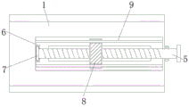
图2是本实用新型螺纹杆截面示意图;Fig. 2 is a schematic cross-sectional view of the utility model threaded rod;
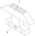
图3是本实用新型联动块立体示意图;Fig. 3 is a three-dimensional schematic diagram of the linkage block of the present invention;
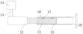
图4是本实用新型弹性板截面示意图。Fig. 4 is a schematic cross-sectional view of the elastic plate of the present invention.
图中:In the picture:
1、底座;2、固定对接架;3、活动对接架;4、电缆对接环;5、螺纹杆;6、承接块;7、限位块;8、联动块;9、导向杆;10、定位杆;11、伸缩杆;12、延长杆;13、支撑杆;14、辅助支架;15、滑动块;16、弹性板;17、顶扣。1. Base; 2. Fixed docking frame; 3. Movable docking frame; 4. Cable docking ring; 5. Threaded rod; 6. Accepting block; 7. Limiting block; 8. Linkage block; 9. Guide rod; 10. Positioning rod; 11, telescopic rod; 12, extension rod; 13, support rod; 14, auxiliary bracket; 15, sliding block; 16, elastic plate; 17, top buckle.
具体实施方式Detailed ways
下面结合附图和实施例对本实用新型的实施方式作进一步详细描述。以下实施例用于说明本实用新型,但不能用来限制本实用新型的范围。The implementation of the present utility model will be further described in detail below in conjunction with the accompanying drawings and examples. The following examples are used to illustrate the utility model, but cannot be used to limit the scope of the utility model.
如图1-4所示,本实用新型提供一种电力线缆对接辅助装置,包括底座1和固定对接架2,所述底座1的表面安装有固定对接架2,所述底座1的表面开口处连接有活动对接架3,所述活动对接架3的开口处安装有电缆对接环4;As shown in Figures 1-4, the utility model provides a power cable docking auxiliary device, including a
所述底座1的一侧连接有螺纹杆5,所述螺纹杆5的一端连接有承接块6,所述螺纹杆5靠近承接块6开口处的一端连接有限位块7,所述螺纹杆5的表面连接有联动块8,所述联动块8的顶端与活动对接架3的底面进行连接,所述联动块8的一侧开口处连接有导向杆9。One side of the
请参考图2,所述限位块7与螺纹杆5为一体结构,所述螺纹杆5通过限位块7与承接块6一侧的开口构成转动结构,通过将限位块7沿着承接块6表面的开口进行旋转,方便将螺纹杆5进行稳定旋转。Please refer to Fig. 2, the said limiting
请参考图2,所述导向杆9的两端均固定在底座1的开口内壁上,所述联动块8表面的开口与导向杆9构成滑动连接结构,通过将导向杆9的使用,防止联动块8移动的过程中发生偏移。Please refer to Fig. 2, both ends of the guide rod 9 are fixed on the inner wall of the opening of the
请参考图4,所述底座1的一端连接有定位杆10,所述定位杆10一端的开口处连接有伸缩杆11,所述伸缩杆11的另一端连接有延长杆12,所述延长杆12的表面安装有支撑杆13,所述支撑杆13的顶部连接有辅助支架14,所述辅助支架14和支撑杆13均为不锈钢材质,通过将辅助支架14的使用,方便对电缆进行支撑。Please refer to Figure 4, one end of the
请参考图4,所述伸缩杆11的底面连接有滑动块15,所述伸缩杆11通过滑动块15与定位杆10内壁对应的滑动槽进行连接,通过将滑动块15沿着定位杆10开口内壁对应的开口进行滑动,方便将伸缩杆11进行导向滑动。Please refer to FIG. 4 , the bottom surface of the
请参考图4,所述伸缩杆11的表面开口处连接有弹性板16,所述弹性板16为柔性不锈钢材质,所述弹性板16的顶部连接有顶扣17,所述弹性板16与顶扣17构成弹性联动结构,通过将顶扣17与定位杆10开口内壁对应的凹槽进行嵌合,方便将辅助支架14进行固定,便于对电缆进行辅助支撑,保证对接的稳定。Please refer to Fig. 4, the surface opening of the
具体工作原理:如图1-4所示,在使用该电力线缆对接辅助装置时,首先通过两个电缆接头分别放置在固定对接架2和活动对接架3的内部,接着旋转螺纹杆5,带动螺纹杆5一端的限位块7沿着承接块6一侧的开口进行旋转,进而带动螺纹杆5表面的联动块8进行移动,同时联动块8的移动,带动联动块8顶端的活动对接架3朝着固定对接架2进行移动,接着带动联动块8沿着导向杆9进行滑动,使得两个电缆进行对中对接,方便提高了电缆对接效率;通过将延长杆12一端的伸缩杆11沿着定位杆10一端的开口进行滑动,带动支撑杆13顶端的辅助支架14进行位置调节,同时带动伸缩杆11底面的滑动块15沿着定位杆10开口对应的滑动槽进行滑动,同时带动顶扣17挤压弹性板16发生形变,直至将辅助支架14拉伸至一定长度,此时顶扣17受到弹性板16的弹性作用力的,使得顶扣17与定位杆10开口内壁对应的凹槽进行嵌合,将辅助支架14延长至一定长度之后进行固定,方便对较长的电缆进行辅助支撑,防止电缆对接时出现翘起的现象,这就是该电力线缆对接辅助装置的特点。Specific working principle: as shown in Figure 1-4, when using the power cable docking auxiliary device, first place the two cable joints inside the fixed
本实用新型的实施方式是为了示例和描述起见而给出的,尽管上面已经示出和描述了本实用新型的实施例,可以理解的是,上述实施例是示例性的,不能理解为对本实用新型的限制,本领域的普通技术人员在本实用新型的范围内可以对上述实施例进行变化、修改、替换和变型。The embodiments of the present utility model are given for the purpose of illustration and description. Although the embodiments of the present utility model have been shown and described above, it can be understood that the above-mentioned embodiments are exemplary and should not be construed as a reference to the present utility model. Novel limitation, those skilled in the art can make changes, modifications, substitutions and modifications to the above-mentioned embodiments within the scope of the present utility model.
Claims (7)
Priority Applications (1)
| Application Number | Priority Date | Filing Date | Title |
|---|---|---|---|
| CN202320431316.0U CN219351147U (en) | 2023-03-09 | 2023-03-09 | Electric power cable butt joint auxiliary device |
Applications Claiming Priority (1)
| Application Number | Priority Date | Filing Date | Title |
|---|---|---|---|
| CN202320431316.0U CN219351147U (en) | 2023-03-09 | 2023-03-09 | Electric power cable butt joint auxiliary device |
Publications (1)
| Publication Number | Publication Date |
|---|---|
| CN219351147U true CN219351147U (en) | 2023-07-14 |
Family
ID=87107099
Family Applications (1)
| Application Number | Title | Priority Date | Filing Date |
|---|---|---|---|
| CN202320431316.0U Expired - Fee Related CN219351147U (en) | 2023-03-09 | 2023-03-09 | Electric power cable butt joint auxiliary device |
Country Status (1)
| Country | Link |
|---|---|
| CN (1) | CN219351147U (en) |
Cited By (1)
| Publication number | Priority date | Publication date | Assignee | Title |
|---|---|---|---|---|
| CN117080948A (en) * | 2023-10-18 | 2023-11-17 | 国网山东省电力公司荣成市供电公司 | A docking auxiliary device for cable terminal processing |
-
2023
- 2023-03-09 CN CN202320431316.0U patent/CN219351147U/en not_active Expired - Fee Related
Cited By (2)
| Publication number | Priority date | Publication date | Assignee | Title |
|---|---|---|---|---|
| CN117080948A (en) * | 2023-10-18 | 2023-11-17 | 国网山东省电力公司荣成市供电公司 | A docking auxiliary device for cable terminal processing |
| CN117080948B (en) * | 2023-10-18 | 2024-01-23 | 国网山东省电力公司荣成市供电公司 | A docking auxiliary device for cable terminal processing |
Similar Documents
| Publication | Publication Date | Title |
|---|---|---|
| CN211004370U (en) | An electrical device lifting and transferring device | |
| CN209608607U (en) | A kind of photovoltaic power generation apparatus facilitating adjusting | |
| CN104386545B (en) | A kind of portable adjustable electric power cable actinobacillus device | |
| CN221833722U (en) | Steel pipe fixing structure | |
| CN106734738B (en) | Bending equipment and forming method for power transmission cable | |
| CN210297210U (en) | Power transmission and transformation engineering cable fixing support | |
| CN219465297U (en) | Hydraulic engineering pipeline is auxiliary fixtures for accurate butt joint | |
| CN219498754U (en) | Threading construction device for building electrical engineering | |
| CN215815370U (en) | A docking device for cable production | |
| CN218801319U (en) | Substation equipment sander | |
| CN214412245U (en) | Special supporting base for cable distribution box | |
| CN211694088U (en) | Medical instrument charger | |
| CN213868167U (en) | Municipal administration is pipe connection for water supply and drainage and lays calibrating device | |
| CN220964902U (en) | A POE power transmission line structure | |
| CN114770584A (en) | Drainage pipe butt-joint structure for road construction | |
| CN111262187B (en) | A secondary line laying auxiliary device for reducing line loss | |
| CN115764730A (en) | A Portable Positioning and Docking Mechanism for 10kV Power Lines | |
| CN112059056A (en) | Angle folding device of high-voltage cable for power transmission line | |
| CN220957114U (en) | Pipeline laying auxiliary device for hydraulic and hydroelectric engineering construction | |
| CN222932611U (en) | Water conservancy pipeline docking equipment | |
| CN221978516U (en) | Pre-buried positioning device for building water and electricity pipelines | |
| CN219504762U (en) | Transformer substation high-voltage equipment overhauls arm | |
| CN221916742U (en) | Power cable conveying device for power communication | |
| CN218386583U (en) | Support frame for cable erection | |
| CN221885889U (en) | An overhead insulated wire peeling device |
Legal Events
| Date | Code | Title | Description |
|---|---|---|---|
| GR01 | Patent grant | ||
| GR01 | Patent grant | ||
| CF01 | Termination of patent right due to non-payment of annual fee | ||
| CF01 | Termination of patent right due to non-payment of annual fee |
Granted publication date: 20230714 |