CN219346313U - Pressing type platform lamp - Google Patents
Pressing type platform lamp Download PDFInfo
- Publication number
- CN219346313U CN219346313U CN202320625167.1U CN202320625167U CN219346313U CN 219346313 U CN219346313 U CN 219346313U CN 202320625167 U CN202320625167 U CN 202320625167U CN 219346313 U CN219346313 U CN 219346313U
- Authority
- CN
- China
- Prior art keywords
- buckle
- lamp
- convex ring
- convex
- integrally formed
- Prior art date
- Legal status (The legal status is an assumption and is not a legal conclusion. Google has not performed a legal analysis and makes no representation as to the accuracy of the status listed.)
- Expired - Fee Related
Links
- 238000009434 installation Methods 0.000 abstract description 7
- 241000237983 Trochidae Species 0.000 description 2
- 238000010586 diagram Methods 0.000 description 2
- 238000005516 engineering process Methods 0.000 description 2
- 238000000034 method Methods 0.000 description 2
- 230000008092 positive effect Effects 0.000 description 2
- 239000011324 bead Substances 0.000 description 1
- 230000002349 favourable effect Effects 0.000 description 1
- 230000017525 heat dissipation Effects 0.000 description 1
- 238000007789 sealing Methods 0.000 description 1
Images
Landscapes
- Non-Portable Lighting Devices Or Systems Thereof (AREA)
Abstract
Description
技术领域technical field
本实用新型属于平台灯技术领域,具体涉及一种抵压式平台灯。The utility model belongs to the technical field of platform lamps, in particular to a pressure-resistant platform lamp.
背景技术Background technique
平台灯是一种常见的照明灯具,其主要是由灯体、灯框和灯罩组成,其灯体和灯框多是通过螺钉进行固定,其虽然可以满足一般情况的使用需求,但是不利于拆装操作;Platform lamp is a common lighting fixture, which is mainly composed of lamp body, lamp frame and lampshade. The lamp body and lamp frame are mostly fixed by screws. Although it can meet the needs of general use, it is not conducive loading operation;
如中国专利公开号为:CN218032783U,专利名称为:一种LED平台灯,包括灯具主体以及可拆卸设置在灯具主体上的灯罩,所述灯具主体在靠近灯罩一端处设有多个被灯罩包裹的灯珠,所述灯具主体的侧部则设有多个散热鳍片,所述灯具主体包括侧壁与顶壳,所述侧壁的顶部设有环形结构的凸壁,而顶壳的底部则设有与凸壁配合的凹槽。For example, the Chinese patent publication number is: CN218032783U, and the patent name is: an LED platform lamp, which includes a lamp body and a lampshade detachably arranged on the lamp body. The lamp bead, the side of the main body of the lamp is provided with a plurality of heat dissipation fins, the main body of the lamp includes a side wall and a top shell, the top of the side wall is provided with a convex wall with a ring structure, and the bottom of the top shell is A groove matching the convex wall is provided.
其是通过凸壁配合凹槽实现扣合,其虽然可以满足安装使用需求,但是在实际应用过程中,其凸壁与凹槽在连接后容易出现松动或脱落的情况,从而影响安装的平稳性,并且其连接处的密封性也较为有限,防尘性能较差,故而适用性和实用性受到限制。It is fastened through the convex wall and the groove. Although it can meet the needs of installation and use, in the actual application process, the convex wall and the groove are prone to loosening or falling off after the connection, which affects the stability of the installation. , and the sealing of its joints is relatively limited, and the dustproof performance is poor, so the applicability and practicability are limited.
发明内容Contents of the invention
本实用新型的目的是提供结构设置合理且有利于提高使用平稳性的一种抵压式平台灯。The purpose of the utility model is to provide a pressure-resisting platform lamp with a reasonable structure and a favorable use stability.
实现本实用新型目的的技术方案是一种抵压式平台灯,包括灯体和灯框,所述灯框的内壁底部一体成型有承载凸环,所述承载凸环的顶面与灯框连接处一体成型有卡位凸环,所述卡位凸环的侧壁上部一体成型有若干个卡扣凸点,所述卡扣凸点处于承载凸环的正上方;The technical solution to achieve the purpose of the utility model is a pressure-resisting platform lamp, including a lamp body and a lamp frame. The bottom of the inner wall of the lamp frame is integrally formed with a bearing convex ring, and the top surface of the bearing convex ring is connected to the lamp frame. A snap ring is integrally formed at the position, and the upper part of the side wall of the snap ring is integrally formed with several buckle bumps, and the snap bumps are directly above the bearing ring;
所述灯体的底面一体成型有向外凸起的卡扣凸边,所述卡扣凸边卡扣在所述承载凸环与卡扣凸点之间定位。The bottom surface of the lamp body is integrally formed with an outwardly protruding buckle flange, and the buckle flange is buckled and positioned between the carrying convex ring and the buckle protrusion.
进一步优选为:所述卡扣凸边上设置有数量与所述卡扣凸点数量相同的避位槽,所述卡扣凸边自避位槽内卡入并旋转使卡扣凸边卡入承载凸环与卡扣凸点之间。It is further preferred that the buckle flange is provided with the same number of avoidance grooves as the number of the buckle convex points, and the buckle flange snaps into the avoidance groove and rotates so that the buckle flange snaps in. Between the bearing lug and the buckle bump.
进一步优选为:所述卡扣凸点为至少四个。Further preferably, there are at least four buckle protrusions.
或者优选为:所述卡扣凸边的厚度等于卡扣凸点与卡位凸环间的高度。Or preferably: the thickness of the buckle flange is equal to the height between the buckle protrusion and the buckle protrusion ring.
或者优选为:所述灯框为塑料结构体。Or preferably: the lamp frame is a plastic structure.
本实用新型具有积极的效果:本实用新型的结构设置合理,其在灯框上设置有承载凸环配合卡扣凸点,同时在灯体上的卡扣凸边,在安装时,直接将灯体的卡扣凸边卡入承载凸环与卡扣凸点之间即可,有利于提高了拆装的便捷性,同时有利于提高使用的平稳性;并且还可以在卡扣凸边上开设避位槽,在安装时卡扣凸点从避位槽内进入并旋转即可,提高了安装的便捷性;而且灯框为塑料结构体,其具有一定的弹性,不但可以提高轻量化,而且在卡扣时可以通过其弹性保证卡扣的有效性,适用性强且实用性好。The utility model has positive effects: the structure of the utility model is reasonably arranged, and the lamp frame is provided with a bearing convex ring to cooperate with buckle bumps, and at the same time, the buckle convex edge on the lamp body can directly connect the lamp The buckle convex edge of the body can be snapped between the carrying convex ring and the buckle convex point, which is conducive to improving the convenience of disassembly and assembly, and at the same time is conducive to improving the stability of use; and it can also be set on the buckle convex edge The avoidance groove, when installing, the buckle protrusion can enter and rotate from the avoidance groove, which improves the convenience of installation; and the light frame is a plastic structure, which has a certain degree of elasticity, which can not only reduce weight, but also When buckling, the effectiveness of the buckling can be guaranteed through its elasticity, and the utility model has strong applicability and good practicability.
附图说明Description of drawings
为了使本实用新型的内容更容易被清楚的理解,下面根据具体实施例并结合附图,对本实用新型作进一步详细的说明,其中:In order to make the content of the utility model easier to understand clearly, the utility model will be described in further detail below according to specific embodiments in conjunction with the accompanying drawings, wherein:
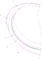
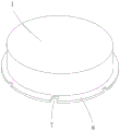
图1为本实用新型的结构示意图;Fig. 1 is the structural representation of the utility model;
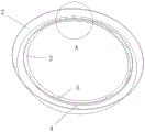
图2为本实用新型中灯框的具体结构示意图;Fig. 2 is the specific structural representation of lamp frame in the utility model;
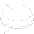
图3为本实用新型中灯体的结构示意图;Fig. 3 is the structural representation of lamp body in the utility model;
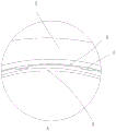
图4为图2中A处放大结构示意图;Figure 4 is a schematic diagram of the enlarged structure at A in Figure 2;
图5为本实用新型中灯体的第二种结构示意图。Fig. 5 is a schematic diagram of the second structure of the lamp body in the present invention.
附图标记:灯体1、灯框2、承载凸环3、卡位凸环4、卡扣凸点5、卡扣凸边6、避位槽7。Reference signs:
具体实施方式Detailed ways
下面将结合本实用新型实施例中的附图,对本实用新型实施例中的技术方案进行清楚、完整地描述,显然,所描述的实施例仅仅是本实用新型一部分实施例,而不是全部的实施例。基于本实用新型中的实施例,本领域普通技术人员在没有做出创造性劳动前提下所获得的所有其他实施例,都属于本实用新型保护的范围。The technical solutions in the embodiments of the present invention will be clearly and completely described below in conjunction with the accompanying drawings in the embodiments of the present invention. Obviously, the described embodiments are only part of the embodiments of the present invention, not all of them. example. Based on the embodiments of the present utility model, all other embodiments obtained by persons of ordinary skill in the art without making creative efforts belong to the scope of protection of the present utility model.
(实施例1)(Example 1)
见图1至图4所示,一种抵压式平台灯,包括灯体1和灯框2,本实施例中,其灯体包括灯壳、光源板和灯罩,此为现有技术的常规结构,其卡扣凸边处于灯壳上。本实施例中,所述灯框为塑料结构体。其具有一定的弹性,不但可以提高轻量化,而且在卡扣时可以通过其弹性保证卡扣的有效性。As shown in Figures 1 to 4, a pressure-resistant platform lamp includes a
所述灯框的内壁底部一体成型有承载凸环3,所述承载凸环的顶面与灯框连接处一体成型有卡位凸环4,所述卡位凸环的侧壁上部一体成型有若干个卡扣凸点5,所述卡扣凸点处于承载凸环的正上方;本实施例中,所述卡扣凸点为至少四个。具体为四个、六个或八个均可。其承载凸环的宽度可以根据需要进行加工设置,而卡扣凸点的宽度小于承载凸环的宽度,而且承载凸环的内径与灯体的卡扣凸边直径相同,即灯体的卡扣凸边在安装时抵接在承载凸环的顶面上,同时卡扣凸边也能卡扣在卡扣凸边的顶面。The bottom of the inner wall of the lamp frame is integrally formed with a
所述灯体的底面一体成型有向外凸起的卡扣凸边6,所述卡扣凸边卡扣在所述承载凸环与卡扣凸点之间定位。本实施例中,所述卡扣凸边的厚度等于卡扣凸点与卡位凸环间的高度。其卡扣凸边的设置主要是用于卡扣在承载凸环与卡扣凸点之间,其为一个完整的卡扣凸边,在安装时是利用塑料的灯框的弹性卡入或拆出。The bottom surface of the lamp body is integrally formed with an outwardly protruding
本实用新型具有积极的效果:本实用新型的结构设置合理,其在灯框上设置有承载凸环配合卡扣凸点,同时在灯体上的卡扣凸边,在安装时,直接将灯体的卡扣凸边卡入承载凸环与卡扣凸点之间即可,有利于提高了拆装的便捷性,同时有利于提高使用的平稳性;并且还可以在卡扣凸边上开设避位槽,在安装时卡扣凸点从避位槽内进入并旋转即可,提高了安装的便捷性;而且灯框为塑料结构体,其具有一定的弹性,不但可以提高轻量化,而且在卡扣时可以通过其弹性保证卡扣的有效性,适用性强且实用性好。The utility model has positive effects: the structure of the utility model is reasonably arranged, and the lamp frame is provided with a bearing convex ring to cooperate with buckle bumps, and at the same time, the buckle convex edge on the lamp body can directly connect the lamp The buckle convex edge of the body can be snapped between the carrying convex ring and the buckle convex point, which is conducive to improving the convenience of disassembly and assembly, and at the same time is conducive to improving the stability of use; and it can also be set on the buckle convex edge The avoidance groove, when installing, the buckle protrusion can enter and rotate from the avoidance groove, which improves the convenience of installation; and the light frame is a plastic structure, which has a certain degree of elasticity, which can not only reduce weight, but also When buckling, the effectiveness of the buckling can be guaranteed through its elasticity, and the utility model has strong applicability and good practicability.
(实施例2)(Example 2)
见图5所示,本实施例与实施例1基本相同,不同之处在于:所述卡扣凸边上设置有数量与所述卡扣凸点数量相同的避位槽7,所述卡扣凸边自避位槽内卡入并旋转使卡扣凸边卡入承载凸环与卡扣凸点之间。采用避位槽,方便卡入及旋转定位。As shown in Figure 5, this embodiment is basically the same as
本实施例中使用的标准零件可以从市场上直接购买,而根据说明书记载的非标准结构部件,也可以直接根据现有的技术常识毫无疑义的加工得到,同时各个零部件的连接方式采用现有技术中成熟的常规手段,而机械、零件及设备均采用现有技术中常规的型号,故在此不再作出具体叙述。The standard parts used in this embodiment can be directly purchased from the market, and the non-standard structural parts recorded according to the instructions can also be processed directly according to the existing technical common sense, and the connection mode of each part adopts existing technology. There are mature conventional means in the technology, and the machinery, parts and equipment all adopt conventional models in the prior art, so no more specific descriptions are made here.
显然,本实用新型的上述实施例仅仅是为清楚地说明本实用新型所作的举例,而并非是对本实用新型的实施方式的限定。对于所属领域的普通技术人员来说,在上述说明的基础上还可以做出其它不同形式的变化或变动。这里无需也无法对所有的实施方式予以穷举。而这些属于本实用新型的实质精神所引伸出的显而易见的变化或变动仍属于本实用新型的保护范围。Apparently, the above-mentioned embodiments of the present utility model are only examples for clearly illustrating the present utility model, rather than limiting the implementation manner of the present utility model. For those of ordinary skill in the art, other changes or changes in different forms can be made on the basis of the above description. It is not necessary and impossible to exhaustively list all the implementation manners here. And these obvious changes or changes derived from the essential spirit of the present utility model still belong to the protection scope of the present utility model.
Claims (5)
Priority Applications (1)
| Application Number | Priority Date | Filing Date | Title |
|---|---|---|---|
| CN202320625167.1U CN219346313U (en) | 2023-03-27 | 2023-03-27 | Pressing type platform lamp |
Applications Claiming Priority (1)
| Application Number | Priority Date | Filing Date | Title |
|---|---|---|---|
| CN202320625167.1U CN219346313U (en) | 2023-03-27 | 2023-03-27 | Pressing type platform lamp |
Publications (1)
| Publication Number | Publication Date |
|---|---|
| CN219346313U true CN219346313U (en) | 2023-07-14 |
Family
ID=87113043
Family Applications (1)
| Application Number | Title | Priority Date | Filing Date |
|---|---|---|---|
| CN202320625167.1U Expired - Fee Related CN219346313U (en) | 2023-03-27 | 2023-03-27 | Pressing type platform lamp |
Country Status (1)
| Country | Link |
|---|---|
| CN (1) | CN219346313U (en) |
-
2023
- 2023-03-27 CN CN202320625167.1U patent/CN219346313U/en not_active Expired - Fee Related
Similar Documents
| Publication | Publication Date | Title |
|---|---|---|
| CN211372116U (en) | A downlight that is easy to disassemble | |
| CN105508920A (en) | LED table lamp | |
| CN208365447U (en) | A snap-on lampshade for LED flood light | |
| CN218721350U (en) | Direct type light-emitting panel lamp with IP65 grade | |
| CN216346099U (en) | A Novel Detachable CONE Connection Structure | |
| CN216591354U (en) | Detachable sectional type annular lamp | |
| CN209926116U (en) | Bamboo joint type lighting assembly capable of being directly loaded on intelligent lamp pole | |
| CN209569561U (en) | A kind of bulb lamp with long service life | |
| CN209622649U (en) | Modular LED tri-proof light | |
| CN210153574U (en) | LED lighting device | |
| CN223204181U (en) | Flying saucer-shaped down lamp | |
| CN209782391U (en) | Mounting structure of embedded lamp | |
| CN218914644U (en) | Ceiling lamp | |
| CN218762828U (en) | Light projector | |
| CN222992753U (en) | Buckle type double-layer lampshade structure | |
| CN214948356U (en) | LED module structure convenient to assembly | |
| CN212029303U (en) | Sealed ceiling lamp | |
| CN220205550U (en) | Lamp set | |
| CN221839567U (en) | A heat dissipation energy-saving lamp | |
| CN218672106U (en) | Combined ceiling lamp with buckle extension structure | |
| CN207049856U (en) | Bulb and PAR lamp tool | |
| CN211450781U (en) | Novel PC cover for illumination | |
| CN216480806U (en) | A lens mounting structure and its stage lamp | |
| CN211952481U (en) | Street light with integrated lamp housing | |
| CN209068323U (en) | A kind of computer room lamp |
Legal Events
| Date | Code | Title | Description |
|---|---|---|---|
| GR01 | Patent grant | ||
| GR01 | Patent grant | ||
| CF01 | Termination of patent right due to non-payment of annual fee |
Granted publication date: 20230714 |
|
| CF01 | Termination of patent right due to non-payment of annual fee |