CN219337777U - Manipulator base convenient to turn to - Google Patents
Manipulator base convenient to turn to Download PDFInfo
- Publication number
- CN219337777U CN219337777U CN202320214156.4U CN202320214156U CN219337777U CN 219337777 U CN219337777 U CN 219337777U CN 202320214156 U CN202320214156 U CN 202320214156U CN 219337777 U CN219337777 U CN 219337777U
- Authority
- CN
- China
- Prior art keywords
- manipulator
- electric cylinder
- box
- box body
- welded
- Prior art date
- Legal status (The legal status is an assumption and is not a legal conclusion. Google has not performed a legal analysis and makes no representation as to the accuracy of the status listed.)
- Active
Links
Images




Classifications
-
- Y—GENERAL TAGGING OF NEW TECHNOLOGICAL DEVELOPMENTS; GENERAL TAGGING OF CROSS-SECTIONAL TECHNOLOGIES SPANNING OVER SEVERAL SECTIONS OF THE IPC; TECHNICAL SUBJECTS COVERED BY FORMER USPC CROSS-REFERENCE ART COLLECTIONS [XRACs] AND DIGESTS
- Y02—TECHNOLOGIES OR APPLICATIONS FOR MITIGATION OR ADAPTATION AGAINST CLIMATE CHANGE
- Y02W—CLIMATE CHANGE MITIGATION TECHNOLOGIES RELATED TO WASTEWATER TREATMENT OR WASTE MANAGEMENT
- Y02W30/00—Technologies for solid waste management
- Y02W30/40—Bio-organic fraction processing; Production of fertilisers from the organic fraction of waste or refuse
Landscapes
- Manipulator (AREA)
Abstract
The utility model provides a manipulator base convenient to turn, which belongs to the technical field of manipulator bases and comprises a rotary disc, a box body, an electric cylinder and a rotating mechanism, wherein the manipulator is fixedly arranged on the top surface of the rotary disc, the rotary disc is arranged at the top of the box body, the bottom of the rotary disc is fixedly connected with a rotary shaft, the rotary shaft is rotationally connected with the box body and stretches into the box body to be matched and connected with the rotating mechanism in the box body, the electric cylinder is fixedly arranged in a mounting hole on the side wall of the box body, and a push rod stretches into the box body to be matched and connected with the rotating mechanism; when this manipulator base can solve the manipulator rotation, adjust the not convenient size of manipulator rotation angle, rotate the not good and quick reverse speed not fast problem of scram effect.
Description
Technical Field
The utility model belongs to the technical field of manipulators, and particularly relates to a manipulator base convenient to turn.
Background
The manipulator is an automatic mechanical device which is most widely applied in the mechanical technical field, the manipulator can simulate certain action functions of hands and arms, and the manipulator is an industrial robot which appears earliest and a modern robot which appears earliest.
The utility model patent of China (application number: CN 202023153155.9) with publication number of CN214604337U discloses a manipulator convenient to turn to, including manipulator body and wheel, the base is installed to the below of manipulator body, and the below of base is provided with the mounting box, the internally mounted of mounting box has driving motor, and driving motor's front end is connected with the driving gear, one side of driving gear is connected with driven gear, driven gear's inside is fixed with the connecting rod, the outer wall of mounting box is provided with the liquid groove, and one side of liquid groove is connected with the flow tube, one side of mounting box is provided with the window, the below of mounting box is fixed with the mount pad, and the inside of mount pad is provided with the cylinder, the front end of cylinder is connected with the fixed foot, mount pad one side is provided with the fixed block, and the inside of fixed block is provided with the spacing groove, fixed block one side is connected with the connecting block, and the internally mounted of connecting block has the gag lever post, the wheel is installed in the below of connecting block.
The current manipulator base adopts this kind of driving motor to directly transmit the connecting rod through gear engagement's mode generally, and when there is the manipulator rotatory, adjust the not convenient size of manipulator rotation angle, rotatory scram effect is not good and quick reverse speed not fast problem.
Disclosure of Invention
In view of the above, the manipulator base convenient for steering provided by the utility model can solve the problems of inconvenient adjustment of the rotation angle of the manipulator, poor rotation scram effect and insufficient rapid reversing speed when the manipulator rotates.
The utility model is realized in the following way:
the utility model provides a manipulator base convenient for steering, which comprises a rotary disc, a box body, an electric cylinder and a rotating mechanism, wherein the manipulator is fixedly arranged on the top surface of the rotary disc, the rotary disc is arranged at the top of the box body, the bottom of the rotary disc is fixedly connected with a rotary shaft, the rotary shaft is rotationally connected with the box body and stretches into the box body to be matched and connected with the rotating mechanism in the box body, and the electric cylinder is fixedly arranged in a mounting hole on the side wall of the box body and stretches into the box body to be matched and connected with the rotating mechanism.
The motion of the electric cylinder push rod is regulated through the regulator, the horizontal motion of the electric cylinder push rod is converted into the rotation of the rotating shaft by the rotating mechanism, the rotating shaft drives the rotating disc to rotate, so that the manipulator installed on the top surface of the rotating disc rotates, the horizontal motion of the electric cylinder push rod is changed into the rotation of the regulating rotating shaft through regulating the rotation of the rotating shaft, the steering of the manipulator is regulated, meanwhile, the motion speed of the electric cylinder can be regulated during the horizontal motion, the rotating speed and the angle of the rotating disc can be regulated due to the property of the motion length, and the scram and the rapid steering function of the electric cylinder enable the rotating disc to realize scram and rapid steering along with the motion of the electric cylinder during the rotation.
On the basis of the technical scheme, the manipulator base convenient to turn can be improved as follows:
the rotating mechanism comprises a mounting column, a transmission belt and a transmission block; the novel electric cylinder is characterized in that a first groove is formed in the side wall of the rotating shaft, the mounting column is fixedly connected with the bottom of the box body, the mounting column is provided with a second groove with the same size and the same height as the first groove, the transmission belt is matched with the second groove in the mounting column to be mounted for transmission through the rotating shaft, the transmission block is fixedly connected to the outer surface of the transmission belt, and the transmission block is welded with the front end of the push rod of the electric cylinder.
The motion of the push rod of the electric cylinder is regulated by the regulator to enable the electric cylinder to push or retract the transmission block, so that the transmission block moves forwards and backwards to drive the transmission belt to drive reversely or clockwise, and the rotation shaft is enabled to rotate according to the transmission direction of the transmission belt through friction force between the transmission belt and the rotation shaft.
Further, a bearing is arranged between the groove of the mounting column and the driving belt, a high-wear-resistant material is adopted in the first groove, the driving belt is made of a high-wear-resistant material, and the straightening part of the driving belt is parallel to the travel path of the electric cylinder.
The length of the straightening part of the driving belt is longer than the stroke length of the electric cylinder, and in order to ensure that the rotating shaft can rotate for one circle under the transmission of the driving belt in the stroke of the electric cylinder, the straightening part is required to be longer than the circumference of the inner circle of the groove of the rotating shaft; the straightening part is parallel to the travel path of the electric cylinder, so that the straightening part of the transmission belt moves along the travel direction of the electric cylinder, the radial force is reduced, and the transmission is more stable.
The electric cylinder is characterized in that a mounting hole is formed in one side wall of the box body and used for mounting the electric cylinder, a bearing is arranged at the top of the electric cylinder in a welded mode, and the rotating shaft stretches into the box body in a matched mode with the bearing.
The box has certain thickness, and is more firm when setting up the mounting hole and installing electronic jar, and can satisfy the pressure that the manipulator during operation brought, and difficult deformation influences the work of manipulator, adopts the bearing cooperation installation, reduces the rotation axis and rotates the frictional loss between with the box.
Further, a gasket is arranged between the top of the box body and the rotating disc, other three side walls of the box body, which are not provided with mounting holes, are detachable, and any one side wall is detachable.
Through placing the gasket between box and rotary disk, can reduce the friction loss to the box when the rotary disk is rotatory, design into detachable style with a lateral wall, dismantle, the convenience is repaiied and is maintained slewing mechanism.
Further, the bottom of the box body is fixedly provided with three wheels which are respectively positioned at three vertex angles of an isosceles triangle.
The manipulator is conveniently moved to a position needing to work by arranging the wheels, and the three wheels form an isosceles triangle, so that the stability of the triangle is utilized to adapt to rough ground.
The electric cylinder is electrically connected with a regulator, and the regulator is used for regulating the advancing speed, the advancing direction and the advancing distance of the push rod of the electric cylinder.
Further, the rotating mechanism comprises the mounting column, the transmission block and a transmission chain; a first gear is sleeved on the side wall of the mounting column, a second gear which is completely the same as the first gear is welded on the side wall of the rotating shaft, and the heights of the two gears are equal; the transmission chain is matched with the two gears, the transmission block is fixedly connected to the outside of the transmission chain, and the transmission block is welded with the front end of the electric cylinder push rod.
The motion of the push rod of the electric cylinder is regulated by the regulator to enable the electric cylinder to push or retract the transmission block, so that the transmission block moves forwards and backwards to drive the transmission chain to rotate reversely or clockwise, and the rotation shaft is enabled to rotate according to the transmission direction of the transmission chain through the cooperation of the transmission chain and the gear between the rotation shaft.
The rotating mechanism comprises a transmission rack, a fixed groove and a fixed column; the transmission rack is welded and connected to the front end of the electric cylinder push rod, the transmission rack is slidably mounted in the fixing groove through key grooves formed in two sides and is meshed and connected with a gear welded on the rotating shaft, and the fixing groove is fixedly connected with the box body through a plurality of fixing columns.
The motion of the push rod of the electric cylinder is regulated by the regulator to enable the electric cylinder to push or retract the transmission rack, so that the transmission rack moves forwards or backwards along the fixed groove, and the transmission rack drives the rotating shaft to rotate clockwise or anticlockwise through meshing with the gear on the rotating shaft.
Further, the number of teeth of the transmission rack is larger than the number of teeth of the gear welded on the rotating shaft.
The number of teeth of the transmission rack is larger than that of the welding gear on the rotating shaft, so that the rotating shaft can rotate clockwise or anticlockwise for one circle in the pushing and pulling process of the transmission rack, and no dead angle exists in rotation.
Compared with the prior art, the manipulator base convenient to turn has the beneficial effects that: the motion of the electric cylinder push rod is regulated through the regulator, the horizontal motion of the electric cylinder push rod is converted into the rotation of the rotating shaft by the rotating mechanism, the rotating shaft drives the rotating disc to rotate, so that the manipulator installed on the top surface of the rotating disc rotates, the horizontal motion of the electric cylinder push rod is changed into the rotation of the regulating rotating shaft through regulating the rotation of the rotating shaft, the steering of the manipulator is regulated, meanwhile, the motion speed of the electric cylinder can be regulated during the horizontal motion, the rotating speed and the angle of the rotating disc can be regulated due to the property of the motion length, and the rotating disc can realize scram and rapid steering along with the motion of the electric cylinder due to the good scram and rapid steering functions during the horizontal motion of the electric cylinder.
Drawings
In order to more clearly illustrate the technical solutions of the embodiments of the present utility model, the drawings that are needed in the description of the embodiments of the present utility model will be briefly described below, it being obvious that the drawings in the following description are only some embodiments of the present utility model, and that other drawings may be obtained according to these drawings without inventive effort for a person skilled in the art.
FIG. 1 is a schematic view of a manipulator base for facilitating steering;
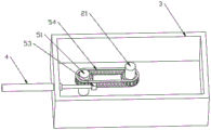
FIG. 2 is a schematic view of the internal structure of a manipulator base for facilitating steering;
FIG. 3 is a schematic view of an embodiment of a manipulator base for facilitating steering;
FIG. 4 is a schematic diagram of a second embodiment of a manipulator base for facilitating steering;
FIG. 5 is a three schematic views of an embodiment of a manipulator base for facilitating steering;
FIG. 6 is a schematic diagram of an electrical connection of a manipulator base to facilitate steering;
in the drawings, the list of components represented by the various numbers is as follows:
1. a manipulator; 2. a rotating disc; 21. a rotation shaft; 3. a case; 31. a wheel; 4. an electric cylinder; 41. a regulator; 5. a rotating mechanism; 51. a mounting column; 52. a transmission belt; 53. a transmission block; 54. a drive chain; 55. a drive rack; 56. a fixing groove; 57. and fixing the column.
Detailed Description
For the purpose of making the objects, technical solutions and advantages of the embodiments of the present utility model more apparent, the technical solutions of the embodiments of the present utility model will be clearly and completely described below with reference to the accompanying drawings in the embodiments of the present utility model, and it is apparent that the described embodiments are some embodiments of the present utility model, but not all embodiments. All other embodiments, based on the embodiments of the utility model, which are apparent to those of ordinary skill in the art without inventive faculty, are intended to be within the scope of the utility model.
Thus, the following detailed description of the embodiments of the utility model, as presented in the figures, is not intended to limit the scope of the utility model, as claimed, but is merely representative of selected embodiments of the utility model. All other embodiments, based on the embodiments of the utility model, which are apparent to those of ordinary skill in the art without inventive faculty, are intended to be within the scope of the utility model.
It should be noted that: like reference numerals and letters denote like items in the following figures, and thus once an item is defined in one figure, no further definition or explanation thereof is necessary in the following figures.
In the description of the present utility model, it should be understood that the terms "center", "longitudinal", "lateral", "length", "width", "thickness", "upper", "lower", "front", "rear", "left", "right", "vertical", "horizontal", "top", "bottom", "inner", "outer", "clockwise", "counterclockwise", etc. indicate orientations or positional relationships based on the orientations or positional relationships shown in the drawings are merely for convenience in describing the present utility model and simplifying the description, and do not indicate or imply that the apparatus or elements referred to must have a specific orientation, be configured and operated in a specific orientation, and thus should not be construed as limiting the present utility model.
Furthermore, the terms "first," "second," and the like, are used for descriptive purposes only and are not to be construed as indicating or implying a relative importance or implicitly indicating the number of technical features indicated. Thus, a feature defining "a first" or "a second" may explicitly or implicitly include one or more such feature. In the description of the present utility model, the meaning of "a plurality" is two or more, unless explicitly defined otherwise.
As shown in fig. 1-3, in this embodiment, the manipulator base for steering is provided, and includes a rotating disc 2, a box 3, an electric cylinder 4 and a rotating mechanism 5, where the manipulator 1 is fixedly installed on the top surface of the rotating disc 2, the rotating disc 2 is placed on top of the box 3, a rotating shaft 21 is fixedly connected to the bottom of the rotating disc 2, the rotating shaft 21 is rotationally connected with the box 3 and stretches into the box 3 to be cooperatively connected with the rotating mechanism 5 in the box 3, and the electric cylinder 4 is fixedly installed in an installation hole on a side wall of the box 3 and stretches into the box 3 to be cooperatively connected with the rotating mechanism 5.
When the manipulator is used, a user pushes the manipulator base to a position where the manipulator works through the wheels 31, the motion of the push rod of the electric cylinder 4 is regulated by using the regulator 41, the rotating speeds of the rotating disc 2 corresponding to different moving speeds of the push rod and the rotating angles of the rotating disc 2 corresponding to different moving distances of the push rod can be obtained through calculation, then the manipulator is controlled to work after the manipulator is regulated by using the regulator 41 according to the required rotating angles.
The manipulator 1 is an industrial robot with the model JZJ200A-270 produced by Jiuzhou Jiurobot limited company, and has the characteristics of long arm extension and large load.
The electric cylinder 4 is a high-power servo electric cylinder with the model FDR110 manufactured by the non-tin Laiyuan mechanical science and technology Co., ltd, and has the characteristics of high compactness and high speed.
The regulator 41 is a direct digital controller with a display screen, model MTCX2, manufactured by the company limited of the european-style electromechanical device in Shenzhen city, which has the characteristic of accomplishing a more complex control function by simple setting.
In the above technical solution, the rotation mechanism 5 includes a mounting post 51, a driving belt 52, and a driving block 53; the side wall of the rotating shaft 21 is provided with a first groove, the mounting column 51 is fixedly connected with the bottom of the box body 3, the mounting column 51 is provided with a second groove with the same size and the same height as the first groove, the transmission belt 52 is matched and mounted through the second grooves formed in the rotating shaft 21 and the mounting column 51 to carry out transmission, the outer surface of the transmission belt 52 is fixedly connected with a transmission block 53, and the transmission block 53 is welded with the front end of the push rod of the electric cylinder 4.
Further, in the above technical solution, a bearing is disposed between the groove of the mounting post 51 and the driving belt 52, the first groove is made of a high wear-resistant material, the driving belt 52 is made of a high wear-resistant material, and the straightened portion of the driving belt 52 is parallel to the travel path of the electric cylinder 4.
When the transmission belt 52 is installed, the transmission belt needs to be straightened and tightened, and the matching is stable.
When in use, the angle obtained by dividing the movement distance of the push rod of the electric cylinder 4 by the radius of the first groove plus the circumferential length of the radius of the thickness of the conveying belt and multiplying the circumferential length by 360 degrees is the rotation angle.
Wherein, in above-mentioned technical scheme, be provided with the mounting hole on box 3 a lateral wall and be used for installing electronic jar 4, the top welding is provided with the bearing, and rotation axis 21 stretches into in the box 3 through with the bearing cooperation.
Further, in the above technical scheme, a gasket is arranged between the top of the box 3 and the rotating disc 2, and other three side walls of the box 3, which are not provided with mounting holes, are detachable.
Further, in the above technical solution, the bottom of the case 3 is fixedly provided with three wheels 31, which are respectively located at three vertex angles of an isosceles triangle.
As shown in fig. 6, in the above-described technical solution, the electric cylinder 4 is electrically connected to the regulator 41, and the regulator 41 is used to regulate the traveling speed, direction and distance of the push rod of the electric cylinder 4.
As shown in fig. 4, a second embodiment of a manipulator base for steering is provided, in which the rotating mechanism 5 includes a mounting post 51, a transmission block 53 and a transmission chain 54; the side wall of the mounting column 51 is sleeved with a first gear, the side wall of the rotating shaft 21 is welded with a second gear which is identical to the first gear, and the heights of the two gears are equal; the transmission chain 54 is matched with the two gears, a transmission block 53 is fixedly connected to the outside of the transmission chain 54, and the transmission block 53 is welded with the front end of the push rod of the electric cylinder 4.
When in use, the angle obtained by dividing the movement distance of the push rod of the electric cylinder 4 by the indexing circumference length of the second gear and multiplying 360 degrees is the rotation angle.
As shown in fig. 5, in a third embodiment of the manipulator base for steering, the rotating mechanism 5 includes a driving rack 55, a fixing slot 56 and a fixing post 57; the transmission rack 55 is welded at the front end of the push rod of the electric cylinder 4, the transmission rack 55 is slidably arranged in the fixed groove 56 through key grooves arranged on two sides and is meshed with a gear welded on the rotating shaft 21, and the fixed groove 56 is fixedly connected with the box body 3 through a plurality of fixed columns 57.
When in use, the angle obtained by dividing the movement distance of the push rod of the electric cylinder 4 by the indexing circumference of the welding gear of the rotating shaft 21 and multiplying 360 degrees is the rotating angle.
Further, in the above technical solution, the number of teeth of the driving rack 55 is greater than the number of teeth of the gear welded on the rotation shaft 21.
Specifically, the principle of the utility model is as follows: the motion of the push rod of the electric cylinder 4 is regulated by the regulator 41, the horizontal motion of the push rod of the electric cylinder 4 is converted into the rotation of the rotating shaft 21 by the rotating mechanism 5, the rotating shaft 21 drives the rotating disc 2 to rotate, so that the manipulator 1 arranged on the top surface of the rotating disc 2 rotates, the steering of the manipulator 1 is regulated by regulating the horizontal motion of the push rod of the electric cylinder 4 to rotate, the motion speed of the manipulator is regulated when the electric cylinder 4 moves horizontally, the rotating speed and the angle of the rotating disc 2 can be regulated due to the property of the motion length, and the sudden stop and the rapid steering function of the electric cylinder 4 can enable the rotating disc 2 to follow the motion of the electric cylinder 4 to realize sudden stop and rapid steering when the rotating.
The foregoing is merely illustrative of the present utility model, and the present utility model is not limited thereto, and any person skilled in the art will readily recognize that variations or substitutions are within the scope of the present utility model. Therefore, the protection scope of the utility model is subject to the protection scope of the claims.
Claims (10)
1. The utility model provides a manipulator base convenient to turn to, its characterized in that includes rotary disk (2), box (3), electronic jar (4) and slewing mechanism (5), manipulator (1) fixed mounting is in the top surface of rotary disk (2), rotary disk (2) are arranged in box (3) top, rotary disk (2) bottom fixedly connected with rotation axis (21), rotation axis (21) with box (3) rotate to be connected and stretch into inside box (3) with inside slewing mechanism (5) cooperation connection of box (3), electronic jar (4) fixed mounting is in the mounting hole on the lateral wall of box (3) and stretch into inside box (3) with slewing mechanism (5) cooperation connection.
2. A manipulator base for facilitating steering according to claim 1, wherein the turning mechanism (5) comprises a mounting post (51), a drive belt (52), a drive block (53); be provided with first recess on the lateral wall of rotation axis (21), erection column (51) with the bottom fixed connection of box (3), erection column (51) be provided with the second recess of the same size of first recess, height, drive belt (52) are through rotation axis (21) with the second recess cooperation installation that erection column (51) set up is transmitted, fixedly connected with on the surface of drive belt (52) drive block (53), drive block (53) with push rod front end welded connection of electronic jar (4).
3. A manipulator base according to claim 2, characterized in that a bearing is arranged between the recess of the mounting post (51) and the drive belt (52), the first recess is made of a highly wear-resistant material, the drive belt (52) is made of a highly wear-resistant material, and the straightening part of the drive belt (52) is parallel to the travel path of the electric cylinder (4).
4. The manipulator base convenient to turn according to claim 1, wherein a mounting hole is formed in a side wall of the box body (3) for mounting the electric cylinder (4), a bearing is welded on the top, and the rotating shaft (21) is matched with the bearing to extend into the box body (3).
5. The manipulator base convenient to turn according to claim 4, wherein a gasket is arranged between the top of the box body (3) and the rotating disc (2), and the box body (3) is not provided with other three side walls of the mounting hole, and any one side wall is detachable.
6. The manipulator base for facilitating steering according to claim 4, wherein the bottom of the box (3) is fixedly provided with three wheels (31) respectively positioned at three vertex angles of an isosceles triangle.
7. A manipulator foot for facilitating steering according to claim 1, characterized in that the electric cylinder (4) is electrically connected to an adjustor (41), the adjustor (41) being adapted to adjust the travelling speed, direction and distance of the push rod of the electric cylinder (4).
8. A manipulator base for facilitating steering according to claim 2, wherein the turning mechanism (5) comprises the mounting post (51), the drive block (53) and a drive chain (54); a first gear is sleeved on the side wall of the mounting column (51), a second gear which is completely the same as the first gear is welded on the side wall of the rotating shaft (21), and the heights of the two gears are equal; the transmission chain (54) is installed in a matched mode with the two gears, the transmission block (53) is fixedly connected to the outside of the transmission chain (54), and the transmission block (53) is connected with the front end of the push rod of the electric cylinder (4) in a welded mode.
9. A manipulator base for facilitating steering according to claim 1, wherein the rotating mechanism (5) comprises a drive rack (55), a fixed slot (56) and a fixed post (57); the transmission rack (55) is welded and connected to the front end of the push rod of the electric cylinder (4), the transmission rack (55) is slidably mounted in the fixing groove (56) through key grooves arranged on two sides and is meshed and connected with a gear welded on the rotating shaft (21), and the fixing groove (56) is fixedly connected with the box body (3) through a plurality of fixing columns (57).
10. A manipulator foot for facilitating steering according to claim 9, wherein the number of teeth of the drive rack (55) is greater than the number of teeth of the gear welded to the rotating shaft (21).
Priority Applications (1)
| Application Number | Priority Date | Filing Date | Title |
|---|---|---|---|
| CN202320214156.4U CN219337777U (en) | 2023-02-15 | 2023-02-15 | Manipulator base convenient to turn to |
Applications Claiming Priority (1)
| Application Number | Priority Date | Filing Date | Title |
|---|---|---|---|
| CN202320214156.4U CN219337777U (en) | 2023-02-15 | 2023-02-15 | Manipulator base convenient to turn to |
Publications (1)
| Publication Number | Publication Date |
|---|---|
| CN219337777U true CN219337777U (en) | 2023-07-14 |
Family
ID=87103745
Family Applications (1)
| Application Number | Title | Priority Date | Filing Date |
|---|---|---|---|
| CN202320214156.4U Active CN219337777U (en) | 2023-02-15 | 2023-02-15 | Manipulator base convenient to turn to |
Country Status (1)
| Country | Link |
|---|---|
| CN (1) | CN219337777U (en) |
Cited By (1)
| Publication number | Priority date | Publication date | Assignee | Title |
|---|---|---|---|---|
| CN116943935A (en) * | 2023-07-26 | 2023-10-27 | 青岛华涛汽车模具有限公司 | Automatic preheating manipulator for automobile bumper before gluing |
-
2023
- 2023-02-15 CN CN202320214156.4U patent/CN219337777U/en active Active
Cited By (1)
| Publication number | Priority date | Publication date | Assignee | Title |
|---|---|---|---|---|
| CN116943935A (en) * | 2023-07-26 | 2023-10-27 | 青岛华涛汽车模具有限公司 | Automatic preheating manipulator for automobile bumper before gluing |
Similar Documents
| Publication | Publication Date | Title |
|---|---|---|
| CN203697006U (en) | Intelligent five-shaft manipulator | |
| CN106041387A (en) | Industrial welding robot | |
| CN209431014U (en) | Lifting device for camera and electronic equipment | |
| CN211639499U (en) | A wheel base adjustable roller support device | |
| CN109533928B (en) | Intermittent feeding mechanism | |
| CN215968716U (en) | A guider for intelligence patrols and examines robot | |
| CN105397840A (en) | Uniaxial joint type mechanical arm | |
| CN212191072U (en) | Forging device with automatically-adjusted stroke | |
| CN2621136Y (en) | Lifting positioning rotation device | |
| CN219093472U (en) | Stainless steel wire straightening device | |
| CN107234384B (en) | Lifting motor drive-type electroplating equipment wielding machine arm | |
| CN209668232U (en) | Continuous intermittent rotary lifting working arm mechanism | |
| CN209407802U (en) | A kind of angle adjusting mechanism of frame welding workbench | |
| CN115610204A (en) | Wheel control mechanism, automobile and use method of wheel control mechanism | |
| CN214446528U (en) | Robot moving platform guided by multiple senses | |
| CN210231344U (en) | Reinforcing bar traction structure and reinforcing bar straightening machine | |
| CN211682116U (en) | A manipulator whose wrist can be rotated at a large angle and industrial equipment using the same | |
| CN213859229U (en) | a gear rack | |
| CN114738475A (en) | Gear shifting executing device for electric automobile | |
| CN114370951A (en) | Automatic temperature measuring equipment for butyronitrile glove production workshop | |
| CN223455979U (en) | A single-axis turntable for precise workpiece measurement and control | |
| CN222023666U (en) | Stacker crane walking equipment | |
| CN216177525U (en) | Ultrasonic welding device | |
| CN223597632U (en) | Stroke amplification mechanism and detection device | |
| CN215826738U (en) | Synchronous steering mechanism of logistics vehicle |
Legal Events
| Date | Code | Title | Description |
|---|---|---|---|
| GR01 | Patent grant | ||
| GR01 | Patent grant |