CN219336910U - Numerical control machine tool fixture tool - Google Patents
Numerical control machine tool fixture tool Download PDFInfo
- Publication number
- CN219336910U CN219336910U CN202320596544.3U CN202320596544U CN219336910U CN 219336910 U CN219336910 U CN 219336910U CN 202320596544 U CN202320596544 U CN 202320596544U CN 219336910 U CN219336910 U CN 219336910U
- Authority
- CN
- China
- Prior art keywords
- slider
- block
- fixedly installed
- plate
- connecting rod
- Prior art date
- Legal status (The legal status is an assumption and is not a legal conclusion. Google has not performed a legal analysis and makes no representation as to the accuracy of the status listed.)
- Expired - Fee Related
Links
Images


Classifications
-
- Y—GENERAL TAGGING OF NEW TECHNOLOGICAL DEVELOPMENTS; GENERAL TAGGING OF CROSS-SECTIONAL TECHNOLOGIES SPANNING OVER SEVERAL SECTIONS OF THE IPC; TECHNICAL SUBJECTS COVERED BY FORMER USPC CROSS-REFERENCE ART COLLECTIONS [XRACs] AND DIGESTS
- Y02—TECHNOLOGIES OR APPLICATIONS FOR MITIGATION OR ADAPTATION AGAINST CLIMATE CHANGE
- Y02P—CLIMATE CHANGE MITIGATION TECHNOLOGIES IN THE PRODUCTION OR PROCESSING OF GOODS
- Y02P90/00—Enabling technologies with a potential contribution to greenhouse gas [GHG] emissions mitigation
- Y02P90/02—Total factory control, e.g. smart factories, flexible manufacturing systems [FMS] or integrated manufacturing systems [IMS]
Landscapes
- Machine Tool Units (AREA)
Abstract
本实用新型公开了一种数控机床夹具工装,涉及夹具技术领域,包括基座,所述基座上固定安装有支撑块,所述基座上滑动安装有第一滑块,所述第一滑块上固定安装有第一连接杆,所述第一滑块上滑动安装有第二滑块,所述第二滑块上固定安装有第二连接杆,所述第一连接杆和第二连接杆上均固定安装有定位板;所述第二滑块上螺纹插设有螺杆,所述螺杆上转动安装有与第二滑块竖直滑动安装的压板,所述第一滑块上竖直滑动安装有压杆,所述压板和压杆的底端均固定安装有硅胶垫。本实用新型通过滑动第一滑块和第二滑块从而调整定位板的位置,以此使得各定位板对不同尺寸的面板进行适配,同时拧紧螺杆将同时对第一滑块和第二滑块进行限位。
The utility model discloses a fixture tooling for a numerically controlled machine tool, which relates to the technical field of fixtures and comprises a base on which a support block is fixedly mounted, a first slide block is slidably mounted on the base, and the first slide A first connecting rod is fixedly installed on the block, a second sliding block is slidably installed on the first sliding block, a second connecting rod is fixedly installed on the second sliding block, and the first connecting rod and the second connecting rod are connected Positioning plates are fixedly installed on the rods; a screw is threadedly inserted on the second slider, and a pressing plate that is vertically slidable with the second slider is installed on the screw, and a vertical sliding plate is installed on the first slider. A pressure bar is slidably installed, and a silicone pad is fixedly installed on the bottom ends of the pressure plate and the pressure bar. The utility model adjusts the position of the positioning plate by sliding the first slider and the second slider, so that each positioning plate can adapt to panels of different sizes, and tightening the screw at the same time will simultaneously adjust the position of the first slider and the second slider. The block is limited.
Description
技术领域technical field
本实用新型涉及夹具技术领域,具体涉及一种数控机床夹具工装。The utility model relates to the technical field of fixtures, in particular to a fixture tooling for a numerically controlled machine tool.
背景技术Background technique
在对汽车面板进行加工时,往往需要使用数控机床进行加工,而在加工过程中通常需要利用夹具工装对其进行夹持限位,从而方便对面板的加工;When processing automobile panels, it is often necessary to use CNC machine tools for processing, and in the process of processing, it is usually necessary to use fixtures to clamp and limit them, so as to facilitate the processing of panels;
如公开号为CN210388428U,名称为《一种汽车面板切割工装》的实用新型专利,其包括工作台,还包括若干固定型块;工作台的台面中部设置有下沉槽,下沉槽内设置有与外部风机连通的除尘抽风口;各固定型块依次环绕设置在下沉槽的边缘处,用于支撑汽车面板;至少一个固定型块旁设置有用于夹紧汽车面板的夹具。本实用新型提高了切割精度和切割质量;For example, the publication number is CN210388428U, and the name is a utility model patent named "A Cutting Tool for Automobile Panel", which includes a workbench and several fixed blocks; A dust removal outlet connected with an external fan; each fixed block is arranged around the edge of the sinking tank in turn to support the automobile panel; at least one of the fixed blocks is provided with a clamp for clamping the automobile panel. The utility model improves cutting precision and cutting quality;
在对汽车面板加工限位过程中,现有部分数控机床的夹具工装通过液压缸进行压合或者利用三爪卡盘等夹具进行夹持,或者有如上述专利所示的进行夹持,但其在进行夹持时,固定型块的位置不能进行调节,从而使得仅能对固定尺寸的面板进行限位,而无法适配其它尺寸的汽车面板。In the process of limiting the processing of automobile panels, the fixtures of some existing CNC machine tools are pressed by hydraulic cylinders or clamped by clamps such as three-jaw chucks, or clamped as shown in the above patents, but they are in When clamping, the position of the fixed block cannot be adjusted, so that only the panel of a fixed size can be limited, and the car panel of other sizes cannot be adapted.
实用新型内容Utility model content
本实用新型的目的是提供一种数控机床夹具工装,以解决现有技术中的上述不足之处。The purpose of this utility model is to provide a kind of fixture tooling of numerical control machine tool, to solve the above-mentioned deficiencies in the prior art.
为了实现上述目的,本实用新型提供如下技术方案:一种数控机床夹具工装,包括基座,所述基座上固定安装有支撑块,所述基座上滑动安装有第一滑块,所述第一滑块上固定安装有第一连接杆,所述第一滑块上滑动安装有第二滑块,所述第二滑块上固定安装有第二连接杆,所述第一连接杆和第二连接杆上均固定安装有定位板;所述第二滑块上螺纹插设有螺杆,所述螺杆上转动安装有与第二滑块竖直滑动安装的压板,所述第一滑块上竖直滑动安装有压杆,所述压板和压杆的底端均固定安装有硅胶垫。In order to achieve the above object, the utility model provides the following technical solutions: a fixture tooling of a numerically controlled machine tool, including a base, a support block is fixedly installed on the base, a first slider is slidably installed on the base, the A first connecting rod is fixedly installed on the first slider, a second slider is slidably installed on the first slider, a second connecting rod is fixedly installed on the second slider, and the first connecting rod and Positioning plates are fixedly installed on the second connecting rods; screw rods are threadedly inserted on the second sliders, and a pressing plate vertically slidably installed on the screw rods is installed on the screw rods; the first sliders A pressure bar is vertically slidably installed on the top, and a silicone pad is fixedly installed on the bottom ends of the pressure plate and the pressure bar.
作为优选,所述第一滑块上固定安装有截面呈T形的顶块。Preferably, a top block with a T-shaped cross section is fixedly installed on the first slider.
作为优选,所述第二滑块底端开设有与压杆尺寸相适配的滑槽。As a preference, the bottom end of the second slider is provided with a chute matching the size of the pressing bar.
作为优选,所述第一滑块的底端固定安装有底块,所述基座上开设有与底块尺寸相适配的移动槽。Preferably, a bottom block is fixedly installed on the bottom end of the first slider, and a moving slot matching the size of the bottom block is opened on the base.
作为优选,所述定位板上转动安装有转板,所述转板上滑动安装有截面呈T形的限位杆,所述限位杆上固定安装有限位板,所述限位杆的短臂端和转板之间固定连接有第一弹簧,所述定位板上设置有限位机构。As a preference, a rotating plate is installed on the positioning plate for rotation, and a limit rod with a T-shaped cross section is slidably mounted on the rotating plate, and a limit plate is fixedly installed on the limit rod, and the short length of the limit rod is A first spring is fixedly connected between the arm end and the rotating plate, and a limit mechanism is arranged on the positioning plate.
作为优选,所述限位机构包括固定安装在定位板上的固定块,所述固定块上水平滑动安装有抵接块,所述抵接块上设置有斜边,所述抵接块远离斜边的一端和固定块内壁之间固定安装有第二弹簧,所述转板上开设有与固定块尺寸相适配的通孔。Preferably, the limit mechanism includes a fixed block fixedly installed on the positioning plate, and an abutment block is horizontally slidably installed on the fixed block, and a hypotenuse is provided on the abutment block, and the abutment block is far away from the oblique A second spring is fixedly installed between one end of the side and the inner wall of the fixed block, and a through hole matching the size of the fixed block is opened on the rotating plate.
作为优选,所述抵接块上固定安装有竖板。Preferably, a riser is fixedly installed on the abutting block.
在上述技术方案中,本实用新型提供一种数控机床夹具工装,具备以下有益效果:通过滑动第一滑块和第二滑块从而调整定位板的位置,以此使得各定位板对不同尺寸的面板进行适配,同时拧紧螺杆将同时对第一滑块和第二滑块进行限位。In the above-mentioned technical solution, the utility model provides a fixture tooling of a numerical control machine tool, which has the following beneficial effects: the position of the positioning plate is adjusted by sliding the first slider and the second slider, so that each positioning plate is suitable for different sizes. The panel is adapted, and the screw rod is tightened at the same time to limit the first slider and the second slider at the same time.
附图说明Description of drawings
为了更清楚地说明本申请实施例或现有技术中的技术方案,下面将对实施例中所需要使用的附图作简单地介绍,显而易见地,下面描述中的附图仅仅是本实用新型中记载的一些实施例,对于本领域普通技术人员来讲,还可以根据这些附图获得其他的附图。In order to more clearly illustrate the technical solutions in the embodiments of the present application or the prior art, the accompanying drawings required in the embodiments will be briefly introduced below. For some embodiments described, those skilled in the art can also obtain other drawings according to these drawings.
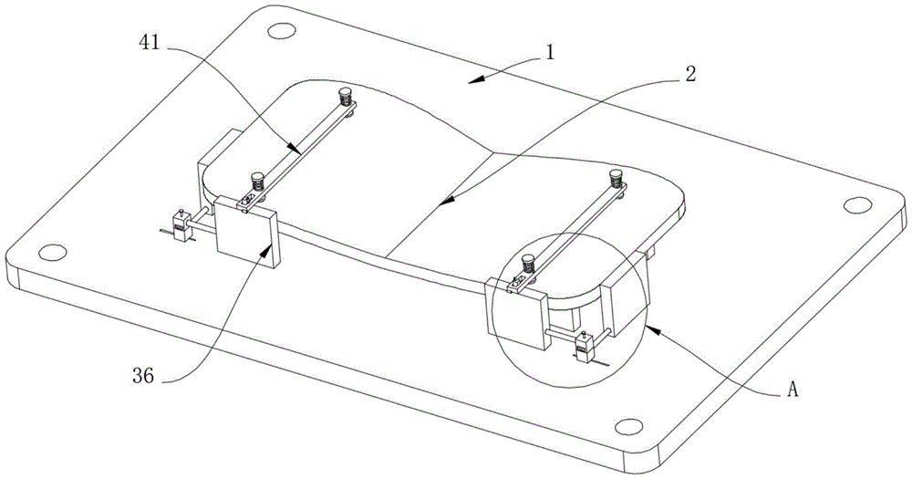
图1为本实用新型实施例提供的立体结构示意图;Fig. 1 is the three-dimensional structure schematic diagram that the utility model embodiment provides;
图2为本实用新型实施例提供图1的A处结构示意图;Fig. 2 provides the structural schematic diagram of A place of Fig. 1 for the utility model embodiment;
图3为本实用新型实施例提供的第一滑块的部分结构示意图;Fig. 3 is a partial structural schematic diagram of the first slider provided by the embodiment of the present invention;
图4为本实用新型实施例提供的第二滑块的部分结构示意图;Fig. 4 is a partial structural schematic diagram of the second slider provided by the embodiment of the present invention;
图5为本实用新型实施例提供的转杆的部分结构示意图。Fig. 5 is a partial structural schematic diagram of the rotating rod provided by the embodiment of the present invention.
附图标记说明:Explanation of reference signs:
1、基座;11、支撑块;2、面板;31、第一滑块;311、第一连接杆;312、顶块;313、底块;32、第二滑块;321、第二连接杆;33、螺杆;34、压板;35、压杆;36、定位板;37、硅胶垫;41、转板;42、限位杆;43、限位板;44、固定块;45、抵接块;451、竖板。1. Base; 11. Support block; 2. Panel; 31. First slider; 311. First connecting rod; 312. Top block; 313. Bottom block; 32. Second slider; 321. Second connection Rod; 33, screw rod; 34, pressure plate; 35, pressure rod; 36, positioning plate; 37, silica gel pad; 41, rotating plate; 42, limit rod; 43, limit plate; 44, fixed block; 45, resist block; 451, vertical board.
具体实施方式Detailed ways
为了使本领域的技术人员更好地理解本实用新型的技术方案,下面将结合附图对本实用新型作进一步的详细介绍。In order to make those skilled in the art better understand the technical solution of the utility model, the utility model will be further introduced in detail below in conjunction with the accompanying drawings.
请参阅图1-5,一种数控机床夹具工装,本实用新型提出的技术方案中,包括基座1,基座1上固定安装有支撑块11,基座1上滑动安装有第一滑块31,第一滑块31上固定安装有第一连接杆311,第一滑块31上滑动安装有第二滑块32,第二滑块32上固定安装有第二连接杆321,第一连接杆311和第二连接杆321上均固定安装有定位板36;第二滑块32上螺纹插设有螺杆33,螺杆33上转动安装有与第二滑块32竖直滑动安装的压板34,第一滑块31上竖直滑动安装有压杆35,压板34和压杆35的底端均固定安装有硅胶垫37;其中可滑动第一滑块31,此时第一滑块31将带动第二滑块32进行滑动,而当第一滑块31在基座1上进行滑动时,其将调节第一连接杆311上的定位板36使其沿着基座1的长棱方向进行移动,从而改变第一连接杆311上定位板36和支撑块11平行表面之间的距离,同时第二连接杆321上的定位板36将同步进行移动,但其与支撑块11平行表面之间的距离不发生变化,而将第二滑块32在第一滑块31上进行滑动时,第二连接杆321上的定位板36其与支撑块11平行表面之间的距离将发生变化,以此通过滑动第一滑块31和第二滑块32将调节各定位板36之间和支撑块11之间的距离,同时也调整各定位板36彼此之间的间距,从而方便各定位板36对面板2进行定位;当第一滑块31和第二滑块32调整好位置后,拧动螺杆33,此时螺杆33将带动压板34挤压第一滑块31,从而限制第一滑块31和第二滑块32之间的移动,而由于压板34底端设置有硅胶垫37,此时硅胶垫37对第一滑块31进行挤压收缩时,压板34将挤压到压杆35,从而随着压板34上硅胶垫37的收缩,压板34也将同步挤压压杆35,从而使得压杆35挤压基座1以此对第一滑块31进行限位,支撑块11上固定安装有橡胶垫。Please refer to Fig. 1-5, a kind of fixture tooling of numerical control machine tool, in the technical scheme proposed by the utility model, comprise
具体的,第一滑块31上固定安装有截面呈T形的顶块312;第一滑块31通过顶块312和第二滑块32进行滑动,压板34上的硅胶垫37的尺寸和顶块312的尺寸相适配从而方便对顶块312进行挤压。Specifically, a
具体的,第二滑块32底端开设有与压杆35尺寸相适配的滑槽;当第二滑块32在第一滑块31顶上进行滑动时,压杆35通过滑槽不会阻碍第二滑块32的移动。Concretely, the bottom end of the
具体的,第一滑块31的底端固定安装有底块313,基座1上开设有与底块313尺寸相适配的移动槽;通过底块313和移动槽的配合,使得第一滑块31方便在基座1上移动,其中压杆35的尺寸大于移动槽的宽度尺寸,从而使得压杆35得以压到基座1表面而不是伸入到移动槽内。Specifically, a
具体的,定位板36上转动安装有转板41,转板41上滑动安装有截面呈T形的限位杆42,限位杆42上固定安装有限位板43,限位杆42的短臂端和转板41之间固定连接有第一弹簧,定位板36上设置有限位机构;当转板41和定位板36转至水平状态时,限位机构将对转板41进行限位,此时转板41上的限位杆42将被第一弹簧拉动朝着面板2的方向移动,这时限位板43将对面板2进行挤压限位。Concretely, a rotating
具体的,限位机构包括固定安装在定位板36上的固定块44,固定块44上水平滑动安装有抵接块45,抵接块45上设置有斜边,抵接块45远离斜边的一端和固定块44内壁之间固定安装有第二弹簧,转板41上开设有与固定块44尺寸相适配的通孔;当转动转板41至水平状态时,转板41上的通孔将越过抵接块45,此时转板41将先抵接到斜边上,从而使得抵接块45朝固定块44内部滑动,直至转板41越过抵接块45,此时抵接块45将被第二弹簧推动而伸出,此时抵接块45将限制转板41向上转。Specifically, the limit mechanism includes a
具体的,抵接块45上固定安装有竖板451;通过竖板451方便对抵接块45进行移动。Specifically, a
尽管已经示出和描述了本实用新型的实施例,对于本领域的普通技术人员而言,可以理解在不脱离本实用新型的原理和精神的情况下可以对这些实施例进行多种变化、修改、替换和变型,本实用新型的范围由所附权利要求及其等同物限定。Although the embodiments of the present invention have been shown and described, those skilled in the art can understand that various changes and modifications can be made to these embodiments without departing from the principle and spirit of the present invention , replacements and modifications, the scope of the present utility model is defined by the appended claims and their equivalents.
Claims (7)
Priority Applications (1)
| Application Number | Priority Date | Filing Date | Title |
|---|---|---|---|
| CN202320596544.3U CN219336910U (en) | 2023-03-24 | 2023-03-24 | Numerical control machine tool fixture tool |
Applications Claiming Priority (1)
| Application Number | Priority Date | Filing Date | Title |
|---|---|---|---|
| CN202320596544.3U CN219336910U (en) | 2023-03-24 | 2023-03-24 | Numerical control machine tool fixture tool |
Publications (1)
| Publication Number | Publication Date |
|---|---|
| CN219336910U true CN219336910U (en) | 2023-07-14 |
Family
ID=87111590
Family Applications (1)
| Application Number | Title | Priority Date | Filing Date |
|---|---|---|---|
| CN202320596544.3U Expired - Fee Related CN219336910U (en) | 2023-03-24 | 2023-03-24 | Numerical control machine tool fixture tool |
Country Status (1)
| Country | Link |
|---|---|
| CN (1) | CN219336910U (en) |
-
2023
- 2023-03-24 CN CN202320596544.3U patent/CN219336910U/en not_active Expired - Fee Related
Similar Documents
| Publication | Publication Date | Title |
|---|---|---|
| CN206140320U (en) | Biax positioning fixture | |
| CN104889708A (en) | Condenser elastic nut installing machine | |
| CN206088336U (en) | Sucker clamp | |
| CN114952648A (en) | Micro clamping device for machining | |
| CN205817366U (en) | A kind of positioning tool for automobile die processing for positioning clamping | |
| CN209319136U (en) | An adjustable jig for aluminum alloy welding | |
| CN211940598U (en) | A mold clamping device with adjustment function | |
| CN213593732U (en) | An automatic press to quickly change the mold | |
| CN211804964U (en) | Camshaft terminal surface machining frock | |
| CN108526928A (en) | A kind of mechanical processing machine work holder | |
| CN218747338U (en) | Positioning and clamping equipment for production of automobile bumper | |
| CN216828124U (en) | Hexagonal stamping die with high machining precision | |
| CN216542518U (en) | A frock clamp for accurate alumina ceramics production and processing | |
| CN114367874B (en) | High-precision copying cutting machine tool | |
| CN206088337U (en) | Sucker clamp | |
| CN217096776U (en) | A pump cover tightening and positioning tool for a gear pump | |
| CN208342321U (en) | A kind of communication aluminum component special fixture | |
| CN211564266U (en) | Positioning tool for die machining | |
| CN204183280U (en) | A kind of Y type balance valve body mesopore fixture for processing device | |
| CN209491555U (en) | A CNC flying saw synchronous fixture device | |
| CN208195828U (en) | A flat mouth device for pipe fitting processing | |
| CN207900268U (en) | A kind of small drilling machine | |
| CN222359134U (en) | A clamping device capable of adjusting a bending machine mold | |
| CN224115658U (en) | A clamp for machining the side of a leaf spring | |
| CN217343851U (en) | Numerical control grooving machine |
Legal Events
| Date | Code | Title | Description |
|---|---|---|---|
| GR01 | Patent grant | ||
| GR01 | Patent grant | ||
| CF01 | Termination of patent right due to non-payment of annual fee |
Granted publication date: 20230714 |
|
| CF01 | Termination of patent right due to non-payment of annual fee |