CN219333622U - Dust-proof awning system device in foundation pit - Google Patents
Dust-proof awning system device in foundation pit Download PDFInfo
- Publication number
- CN219333622U CN219333622U CN202223436386.XU CN202220436386U CN219333622U CN 219333622 U CN219333622 U CN 219333622U CN 202220436386 U CN202220436386 U CN 202220436386U CN 219333622 U CN219333622 U CN 219333622U
- Authority
- CN
- China
- Prior art keywords
- dust
- plate
- system device
- foundation pit
- dust blocking
- Prior art date
- Legal status (The legal status is an assumption and is not a legal conclusion. Google has not performed a legal analysis and makes no representation as to the accuracy of the status listed.)
- Expired - Fee Related
Links
Images


Landscapes
- Buildings Adapted To Withstand Abnormal External Influences (AREA)
Abstract
Description
技术领域technical field
本实用新型涉及基坑降尘技术领域,尤其涉及一种基坑内防扬尘天幕系统装置。The utility model relates to the technical field of dust suppression in foundation pits, in particular to a dust-proof sky curtain system device in foundation pits.
背景技术Background technique
随着生活水平的提高,人们对生活环境的要求越来越高,尤其在繁华闹市,人口密度较大,大型基坑施工场地环形道路车辆行驶频率高,场地扬尘的产生昼夜频繁且范围较为分散,传统基坑周边喷淋降尘系统,多采用高压喷枪设备,且水源以市政用水为主,在降尘需求要求较高情况下,移动设备无法保证大范围整体降尘效果;并且长时间的降尘用水需求量大,水资源消耗大。With the improvement of living standards, people's requirements for the living environment are getting higher and higher, especially in the bustling city, the population density is relatively high, the frequency of vehicles on the circular road of the large-scale foundation pit construction site is high, and the dust generated on the site is frequent day and night and the range is relatively scattered. , the traditional sprinkler dust reduction system around the foundation pit mostly uses high-pressure spray gun equipment, and the water source is mainly municipal water. In the case of high dust reduction requirements, mobile equipment cannot guarantee the overall dust reduction effect in a large area; and the long-term dust reduction water demand The amount is large, and the consumption of water resources is large.
在公开号为CN114182986A的中国发明专利中公开了一种基坑降尘天幕系统,针对上述中的相关技术,该实用新型存在以下缺陷:该专利在进行使用时当需要进行降尘时工人会启动一个水泵,水泵将水箱内的水抽取出,并且输送至第一管内,再由第一管上的雾化喷头喷出,起到降尘降温的的作用,该喷头在进行喷洒的过程中无法对喷头的喷洒角度进行调节,只能向同一个方向进行喷洒,使喷洒的范围较小,进而无法有效的进行降尘。In the Chinese invention patent whose publication number is CN114182986A, a foundation pit dust suppression sky curtain system is disclosed. For the above-mentioned related technologies, this utility model has the following defects: the worker will start a water pump when the patent needs to carry out dust suppression when it is in use. , the water pump extracts the water in the water tank, and transports it to the first pipe, and then sprays it out from the atomizing nozzle on the first pipe, which plays the role of reducing dust and cooling. The spraying angle is adjusted, and it can only be sprayed in the same direction, so that the spraying range is small, and the dust cannot be effectively suppressed.
实用新型内容Utility model content
为解决现有技术中无法对喷头的喷洒角度进行调节,只能向同一个方向进行喷洒的技术问题,本实用新型提供一种基坑内防扬尘天幕系统装置。In order to solve the technical problem in the prior art that the spraying angle of the nozzle cannot be adjusted and can only be sprayed in the same direction, the utility model provides an anti-dust sky curtain system device in a foundation pit.
本实用新型采用以下技术方案实现:一种基坑内防扬尘天幕系统装置,包括两个支架,以及安装在两个支架之间的挡尘机构,所述支架包括两个支撑板,以及安装在两个支撑板顶部的固定板,所述挡尘机构的内部安装有喷淋机构,所述喷淋机构包括两个升降板,以及转动连接在两个升降板之间的多个喷水管,所述喷水管的底部安装有多个喷头,其中一个所述升降板的一侧安装有驱动多个喷水管进行摆动的摆动机构;The utility model is realized by adopting the following technical proposals: a dust-proof sky curtain system device in a foundation pit, including two brackets, and a dust-proof mechanism installed between the two brackets, the bracket includes two support plates, and is installed on two A fixed plate on the top of a support plate, a sprinkler mechanism is installed inside the dust blocking mechanism, and the sprinkler mechanism includes two lifting plates, and a plurality of water spray pipes that are rotatably connected between the two lifting plates, so that The bottom of the water spray pipe is equipped with a plurality of nozzles, and one side of the lifting plate is equipped with a swing mechanism that drives a plurality of water spray pipes to swing;
所述摆动机构包括滑动连接在其中一个升降板一侧的移动板,安装在该升降板一侧的安装板,安装在安装板一侧用于驱动移动板进行往复运动的驱动机构,以及安装在移动板顶部的齿条,所述喷水管的外部安装有与齿条啮合的齿轮。The swing mechanism includes a moving plate slidably connected to one side of the lifting plate, a mounting plate installed on one side of the lifting plate, a driving mechanism installed on the side of the mounting plate for driving the moving plate to reciprocate, and mounted on the A toothed rack on the top of the moving plate, and a gear meshed with the toothed rack is mounted on the outside of the spray pipe.
作为上述方案的进一步改进,所述挡尘机构包括安装在两个固定板之间的第一挡尘布,以及安装在四个支撑板之间的两个第二挡尘布,且两个第二挡尘布位于第一挡尘布相对应的两侧。As a further improvement of the above solution, the dust-proof mechanism includes a first dust-proof cloth installed between two fixing plates, and two second dust-proof cloths installed between four support plates, and the two second The second dust-proof cloth is located on the corresponding two sides of the first dust-proof cloth.
通过上述技术方案,可以将基坑进行遮挡,减少灰尘飞扬的现象。Through the above technical solution, the foundation pit can be covered to reduce the phenomenon of flying dust.
作为上述方案的进一步改进,所述驱动机构包括旋转柱,安装在安装板一侧套筒,滑动连接在套筒内部的滑动板,以及开设在滑动板内部的圆形槽,所述旋转柱位于圆形槽的内部,所述旋转柱的外部开设有波浪形结构的滑动槽,所述滑动槽的内部滑动连接有两个滚珠,两个所述滚珠的一侧均通过连接杆与圆形槽的内壁固定连接,所述滑动板的一侧安装有移动杆,且移动杆的一端延伸至套筒的外部并与移动板的一侧固定连接。As a further improvement of the above solution, the drive mechanism includes a rotating column, a sleeve installed on one side of the mounting plate, a sliding plate slidably connected inside the sleeve, and a circular groove opened inside the sliding plate. The rotating column is located at Inside the circular groove, a sliding groove with a wave-shaped structure is provided on the outside of the rotating column. Two balls are slidably connected to the inside of the sliding groove, and one side of the two balls is connected to the circular groove through a connecting rod. The inner wall of the sliding plate is fixedly connected, a moving rod is installed on one side of the sliding plate, and one end of the moving rod extends to the outside of the sleeve and is fixedly connected to one side of the moving plate.
通过上述技术方案,可以使移动板进行往复的运动。Through the above technical solution, the moving plate can be made to perform reciprocating motion.
作为上述方案的进一步改进,所述安装板的一侧安装有驱动旋转柱旋转的旋转电机。As a further improvement of the above solution, a rotating motor that drives the rotating column to rotate is installed on one side of the mounting plate.
通过上述技术方案,可以驱动旋转柱进行旋转。Through the above technical solution, the rotating column can be driven to rotate.
作为上述方案的进一步改进,所述固定板的底部安装有两个气压缸,两个所述气压缸的输出端分别与两个升降板的顶部固定连接。As a further improvement of the above solution, two pneumatic cylinders are installed on the bottom of the fixed plate, and the output ends of the two pneumatic cylinders are respectively fixedly connected to the tops of the two lifting plates.
通过上述技术方案,可以对升降板的高度进行调节,进而可以对喷淋机构的高度进行调节,从而可以调节喷淋机构在不同环境下需要进行降尘的间距,从而可以更加有效的进行降尘。Through the above technical solution, the height of the lifting plate can be adjusted, and then the height of the spraying mechanism can be adjusted, so that the distance between the spraying mechanism for dust reduction in different environments can be adjusted, so that dust can be reduced more effectively.
作为上述方案的进一步改进,另一个所述升降板的一侧安装有水泵和条形管,多个所述喷水管均延伸至条形管的内部,且与条形管的连接处转动连接,所述水泵的进口安装有进水管,且水泵的出口通过出水管与条形管连通。As a further improvement of the above solution, a water pump and a strip pipe are installed on one side of the other lifting plate, and a plurality of the water spray pipes extend to the inside of the strip pipe and are rotatably connected to the junction of the strip pipe , the inlet of the water pump is equipped with a water inlet pipe, and the outlet of the water pump communicates with the strip pipe through the water outlet pipe.
通过上述技术方案,可以将外部的水抽入到多个喷水管内。Through the above technical solution, the external water can be pumped into a plurality of water spray pipes.
相比现有技术,本实用新型的有益效果在于:Compared with the prior art, the beneficial effects of the utility model are:
本实用新型在进行降尘的过程中,可以使喷头进行往复的摆动,从而可以对喷头的喷洒角度进行调节,这样可以扩大喷头进行喷洒的范围,从而进一步提高了降尘的效果。In the process of dust reduction, the utility model can make the nozzle swing back and forth, thereby adjusting the spraying angle of the nozzle, so that the spraying range of the nozzle can be expanded, thereby further improving the effect of dust reduction.
附图说明Description of drawings
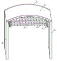
图1为本实用新型的第一立体结构示意图;Fig. 1 is the first three-dimensional structure schematic diagram of the present utility model;
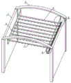
图2为本实用新型的第二立体结构示意图;Fig. 2 is the second three-dimensional structure schematic diagram of the present utility model;
图3为本实用新型的图2中A处的放大结构示意图;Fig. 3 is the enlarged schematic diagram of the structure at A in Fig. 2 of the present utility model;
图4为本实用新型的图2中B处的放大结构示意图;Fig. 4 is the enlarged schematic diagram of the structure at B in Fig. 2 of the present utility model;
图5为本实用新型的图1中C处的放大结构示意图;Fig. 5 is the enlarged structural schematic diagram of C place in Fig. 1 of the present utility model;
图6为本实用新型的驱动机构的剖视结构示意图;Fig. 6 is a sectional structural schematic diagram of the driving mechanism of the present utility model;
主要符号说明:Description of main symbols:
1、支撑板;2、固定板;3、第二挡尘布;4、第一挡尘布;5、升降板;6、喷水管;7、喷头;8、安装板;9、套筒;10、移动杆;11、移动板;12、齿条;13、齿轮;14、旋转柱;15、滑动槽;16、滚珠;17、旋转电机;18、气压缸;19、滑动板;20、条形管;21、水泵。1. Support plate; 2. Fixed plate; 3. Second dust cloth; 4. First dust cloth; 5. Lifting plate; 6. Spray pipe; 7. Nozzle; 8. Mounting plate; ;10, moving rod; 11, moving plate; 12, rack; 13, gear; 14, rotating column; 15, sliding groove; 16, ball; 17, rotating motor; 18, air cylinder; , strip tube; 21, water pump.
具体实施方式Detailed ways
下面,结合附图以及具体实施方式,对本实用新型做进一步描述,需要说明的是,在不相冲突的前提下,以下描述的各实施例之间或各技术特征之间可以任意组合形成新的实施例。Below, the utility model will be further described in conjunction with the accompanying drawings and specific implementation methods. It should be noted that, on the premise of not conflicting, the various embodiments or technical features described below can be combined arbitrarily to form new implementations. example.
实施例1:Example 1:
请结合图1-6,本实施例的一种基坑内防扬尘天幕系统装置,包括两个支架,以及安装在两个支架之间的挡尘机构,挡尘机构包括安装在两个固定板2之间的第一挡尘布4,以及安装在四个支撑板1之间的两个第二挡尘布3,且两个第二挡尘布3位于第一挡尘布4相对应的两侧,支架包括两个支撑板1,以及安装在两个支撑板1顶部的固定板2,挡尘机构的内部安装有喷淋机构,喷淋机构包括两个升降板5,以及转动连接在两个升降板5之间的多个喷水管6,喷水管6的底部安装有多个喷头7,其中一个升降板5的一侧安装有驱动多个喷水管6进行摆动的摆动机构;另一个升降板5的一侧安装有水泵21和条形管20,多个喷水管6均延伸至条形管20的内部,且与条形管20的连接处转动连接,水泵21的进口安装有进水管,且水泵21的出口通过出水管与条形管20连通,摆动机构包括滑动连接在其中一个升降板5一侧的移动板11,安装在该升降板5一侧的安装板8,安装在安装板8一侧用于驱动移动板11进行往复运动的驱动机构,以及安装在移动板11顶部的齿条12,喷水管6的外部安装有与齿条12啮合的齿轮13,在进行降尘的过程中,在摆动机构的作用下可以使喷头进行往复的摆动,从而可以对喷头的喷洒角度进行调节,这样可以扩大喷头进行喷洒的范围,从而进一步提高了降尘的效果,驱动机构包括旋转柱14,安装在安装板8一侧套筒9,滑动连接在套筒9内部的滑动板19,以及开设在滑动板19内部的圆形槽,旋转柱14位于圆形槽的内部,旋转柱14的外部开设有波浪形结构的滑动槽15,滑动槽15的内部滑动连接有两个滚珠16,两个滚珠16的一侧均通过连接杆与圆形槽的内壁固定连接,滑动板19的一侧安装有移动杆10,且移动杆10的一端延伸至套筒9的外部并与移动板11的一侧固定连接,安装板8的一侧安装有驱动旋转柱14旋转的旋转电机17,当旋转柱14进行旋转时,两个滚珠16会在滑动槽15的内部进行同步的往复运动。Please refer to Fig. 1-6, a kind of dust-proof sky curtain system device in the foundation pit of this embodiment includes two brackets and a dust-proof mechanism installed between the two brackets. The dust-proof mechanism includes two fixed plates 2 The first dust cloth 4 between them, and the two
本申请实施例中一种基坑内防扬尘天幕系统装置的实施原理为:首先将外部的水管与进水管固定连接,当需要对基坑进行降尘时,水泵21和旋转电机17会进行工作,水泵21会将外部的水抽入到条形管20的内部,进入到条形管20内部的水会分流到多个喷水管6中,最后通过多个喷头7喷洒出来,在进行喷洒的过程中,旋转电机17会带动旋转柱14进行旋转,当旋转柱14进行旋转时,在滑动槽15的作用下,会使两个滚珠16会在滑动槽15的内部进行同步的往复运动,从而会使滑动板19进行往复的运动,在滑动板19的带动下会使移动杆10进行往复运动,进而会使移动板11进行往复的滑动,当移动板11进行移动时会带动齿条12进行移动,在齿条12与齿轮13的啮合下,会使齿轮13进行往复的正反旋转,进而会使喷水管6进行往复的正反转动,当喷水管6进行转动时,会对多个喷头7的喷洒角度进行调节,这样可以扩大喷头7进行喷洒的范围,从而进一步提高了降尘的效果。In the embodiment of the present application, the implementation principle of an anti-dust canopy system device in a foundation pit is as follows: firstly, the external water pipe is fixedly connected to the water inlet pipe. 21 will pump the external water into the inside of the
实施例2:Example 2:
结合图1-6,本实施例与实施例1的区别在于:固定板2的底部安装有两个气压缸18,两个气压缸18的输出端分别与两个升降板5的顶部固定连接。1-6, the difference between this embodiment and embodiment 1 is that two
本实施例在实施例1的基础上,进一步改进的工作原理在于:通过设有的气压缸18可以对升降板5的高度进行调节,进而可以对喷淋机构的高度进行调节,从而可以调节喷淋机构在不同环境下需要进行降尘的间距,从而可以更加有效的进行降尘。On the basis of Embodiment 1, the working principle of this embodiment is further improved: the height of the
上述实施方式仅为本实用新型的优选实施方式,不能以此来限定本实用新型保护的范围,本领域的技术人员在本实用新型的基础上所做的任何非实质性的变化及替换均属于本实用新型所要求保护的范围。The above-mentioned embodiments are only preferred embodiments of the present utility model, and cannot be used to limit the scope of protection of the present utility model. The scope of protection required by the utility model.
Claims (6)
Priority Applications (1)
| Application Number | Priority Date | Filing Date | Title |
|---|---|---|---|
| CN202223436386.XU CN219333622U (en) | 2022-12-22 | 2022-12-22 | Dust-proof awning system device in foundation pit |
Applications Claiming Priority (1)
| Application Number | Priority Date | Filing Date | Title |
|---|---|---|---|
| CN202223436386.XU CN219333622U (en) | 2022-12-22 | 2022-12-22 | Dust-proof awning system device in foundation pit |
Publications (1)
| Publication Number | Publication Date |
|---|---|
| CN219333622U true CN219333622U (en) | 2023-07-14 |
Family
ID=87075012
Family Applications (1)
| Application Number | Title | Priority Date | Filing Date |
|---|---|---|---|
| CN202223436386.XU Expired - Fee Related CN219333622U (en) | 2022-12-22 | 2022-12-22 | Dust-proof awning system device in foundation pit |
Country Status (1)
| Country | Link |
|---|---|
| CN (1) | CN219333622U (en) |
Cited By (3)
| Publication number | Priority date | Publication date | Assignee | Title |
|---|---|---|---|---|
| CN117211832A (en) * | 2023-10-25 | 2023-12-12 | 中国十七冶集团有限公司 | A track-type automatic shotcrete trolley system and its use method |
| CN117822920A (en) * | 2024-01-26 | 2024-04-05 | 中建三局集团华南有限公司 | Backdrop device capable of adaptively adjusting spray opening and closing angles and adjusting method |
| CN120586556A (en) * | 2025-06-18 | 2025-09-05 | 安徽权鹏建筑有限公司 | A dust suppression device for municipal engineering foundation pit construction |
-
2022
- 2022-12-22 CN CN202223436386.XU patent/CN219333622U/en not_active Expired - Fee Related
Cited By (3)
| Publication number | Priority date | Publication date | Assignee | Title |
|---|---|---|---|---|
| CN117211832A (en) * | 2023-10-25 | 2023-12-12 | 中国十七冶集团有限公司 | A track-type automatic shotcrete trolley system and its use method |
| CN117822920A (en) * | 2024-01-26 | 2024-04-05 | 中建三局集团华南有限公司 | Backdrop device capable of adaptively adjusting spray opening and closing angles and adjusting method |
| CN120586556A (en) * | 2025-06-18 | 2025-09-05 | 安徽权鹏建筑有限公司 | A dust suppression device for municipal engineering foundation pit construction |
Similar Documents
| Publication | Publication Date | Title |
|---|---|---|
| CN113235832B (en) | Building roof rainwater collecting and utilizing system based on sponge city idea | |
| CN112246053A (en) | Spraying dust removal device for construction site | |
| CN110237623A (en) | A kind of construction environmental protection device for reducing dust | |
| CN117482674A (en) | Construction dust fall equipment | |
| CN221752742U (en) | Rotary water-spraying dust-settling device | |
| CN110812992B (en) | A water spray dust removal equipment for green building construction | |
| CN216799201U (en) | Construction site watering dust keeper for building engineering of range of spraying adjustable | |
| CN117815797A (en) | Portable dust purification device and purification method for building construction | |
| CN216677519U (en) | Environmental protection dust collector for construction | |
| CN110102129A (en) | A kind of efficient depositing dust machine of civil engineering | |
| CN115573421A (en) | Green building roof structure | |
| CN214130860U (en) | Building construction working face sprays dust device | |
| CN218833980U (en) | Environment-friendly energy-saving dust falling device for green building construction | |
| CN216304539U (en) | Urban municipal rainwater collection device | |
| CN115467542A (en) | a curtain wall system | |
| CN215027237U (en) | A dust removal device for highway construction | |
| CN221321875U (en) | Automatic operation construction equipment is decorated to building curtain outer wall fitment | |
| CN217139762U (en) | Dust device for construction | |
| CN224056923U (en) | Rotatory fog stake of multimode regulation | |
| CN220047564U (en) | Spraying dust device | |
| CN217490243U (en) | A kind of environmental protection building construction equipment | |
| CN221663538U (en) | Dust-raising-preventing auxiliary device for construction site | |
| CN220360922U (en) | A dust reduction device for green building construction | |
| CN219984266U (en) | Rotatable environment-friendly dust fall equipment | |
| CN223930982U (en) | A dust suppression spraying device for municipal construction |
Legal Events
| Date | Code | Title | Description |
|---|---|---|---|
| GR01 | Patent grant | ||
| CF01 | Termination of patent right due to non-payment of annual fee |
Granted publication date: 20230714 |