CN219333396U - Sewage treatment purifying mechanism - Google Patents
Sewage treatment purifying mechanism Download PDFInfo
- Publication number
- CN219333396U CN219333396U CN202320690199.XU CN202320690199U CN219333396U CN 219333396 U CN219333396 U CN 219333396U CN 202320690199 U CN202320690199 U CN 202320690199U CN 219333396 U CN219333396 U CN 219333396U
- Authority
- CN
- China
- Prior art keywords
- bevel gear
- filter
- tank
- sewage treatment
- filter tank
- Prior art date
- Legal status (The legal status is an assumption and is not a legal conclusion. Google has not performed a legal analysis and makes no representation as to the accuracy of the status listed.)
- Active
Links
Images
Classifications
-
- Y—GENERAL TAGGING OF NEW TECHNOLOGICAL DEVELOPMENTS; GENERAL TAGGING OF CROSS-SECTIONAL TECHNOLOGIES SPANNING OVER SEVERAL SECTIONS OF THE IPC; TECHNICAL SUBJECTS COVERED BY FORMER USPC CROSS-REFERENCE ART COLLECTIONS [XRACs] AND DIGESTS
- Y02—TECHNOLOGIES OR APPLICATIONS FOR MITIGATION OR ADAPTATION AGAINST CLIMATE CHANGE
- Y02W—CLIMATE CHANGE MITIGATION TECHNOLOGIES RELATED TO WASTEWATER TREATMENT OR WASTE MANAGEMENT
- Y02W10/00—Technologies for wastewater treatment
- Y02W10/10—Biological treatment of water, waste water, or sewage
Landscapes
- Filtration Of Liquid (AREA)
Abstract
本实用新型公开了一种污水处理净化机构,涉及污水处理净化装置领域,包括处理池,所述处理池的内部安装有升降组件,且升降组件包括有电机、第一锥型齿轮、传动轴、第二锥型齿轮、第三锥型齿轮、丝杆、外壳体、活动块和连接板,所述连接板上方设置有过滤槽,且过滤槽内部设置有第一过滤板,所述第一过滤板的一侧安装有第二过滤板。本实用新型通过设置的电机、第一锥型齿轮、传动轴、第二锥型齿轮、第三锥型齿轮、丝杆、外壳体、活动块和连接板,实现便于带动过滤槽移动,使过滤槽移动至处理池上表面,以便于工作人员对过滤槽内部的杂质进行清理,通过电机转动带动过滤槽移动,操作起来更加省力。
The utility model discloses a sewage treatment and purification mechanism, which relates to the field of sewage treatment and purification devices, and comprises a treatment pool. A lifting assembly is installed inside the treatment pool, and the lifting assembly includes a motor, a first bevel gear, a transmission shaft, The second bevel gear, the third bevel gear, the screw mandrel, the outer casing, the movable block and the connecting plate, a filter tank is arranged above the connecting plate, and a first filter plate is arranged inside the filter tank, and the first filter One side of the plate is fitted with a second filter plate. The utility model is provided with a motor, a first bevel gear, a transmission shaft, a second bevel gear, a third bevel gear, a screw rod, an outer shell, a movable block and a connecting plate, so as to facilitate the movement of the filter tank and make the filter The tank moves to the upper surface of the treatment tank, so that the staff can clean up the impurities inside the filter tank, and the filter tank moves through the rotation of the motor, which is more labor-saving to operate.
Description
技术领域technical field
本实用新型涉及污水处理净化装置领域,具体为一种污水处理净化机构。The utility model relates to the field of sewage treatment and purification devices, in particular to a sewage treatment and purification mechanism.
背景技术Background technique
污水处理是为使污水达到排入某一水体或再次使用的水质要求对其进化净化的过程,污水处理被广泛应用于建筑、农业、交通、能源、石化、环保、城市景观、医疗、餐饮等各个领域,也越来越多地走进寻常百姓的日常生活。Sewage treatment is the process of evolution and purification of sewage to meet the water quality requirements for discharge into a certain water body or reuse. Sewage treatment is widely used in construction, agriculture, transportation, energy, petrochemical, environmental protection, urban landscape, medical treatment, catering, etc. Various fields are also increasingly entering the daily life of ordinary people.
在对居民生活污水处理过程中,需要利用污水处理池来对生活污水进行处理,且生活污水中含有较多的杂质,在对生活污水时,应当将污水内部的杂质进行去除,以保证下一步工序对污水进行处理,且现有的去除生活污水内部杂质的方法多采用人工打捞的办法,去除起来工作效率较低。In the process of domestic sewage treatment of residents, it is necessary to use sewage treatment tanks to treat domestic sewage, and domestic sewage contains more impurities. When treating domestic sewage, impurities inside the sewage should be removed to ensure the next step The process treats the sewage, and the existing methods for removing impurities inside the domestic sewage mostly use manual salvage, which has low work efficiency.
中国专利公开号:CN217746032U公开了《一种居民生活污水处理净化机构》,包括池体,所述池体的侧壁上设有排水件,且池体的内部侧面上部边缘处固定连接有U型滤板,且池体内壁位于U型滤板的正下方处贴合有倾斜的L型滤板,所述L型滤板的下端四角处均固定连接有弹簧,四根所述弹簧的下端均固定连接有方块,且四根弹簧的内侧均设有导向件,四块所述方块均固定连接在池体的内壁上,该装置的有益效果是在对居民生活污水中的较大杂质、较小杂质进行初步过滤时可实现便于将过滤后的较大杂质与较小杂质给清理出来,同时用于过滤较大杂质与较小的杂质的U型滤板与L型滤板不易发生堵塞,使用方便。Chinese Patent Publication No.: CN217746032U discloses "A Residential Sewage Treatment and Purification Mechanism", which includes a pool body, the side wall of the pool body is provided with drainage parts, and the upper edge of the inner side of the pool body is fixedly connected with a U-shaped filter plate, and the inner wall of the tank is located directly below the U-shaped filter plate and is fitted with an inclined L-shaped filter plate. The four corners of the lower end of the L-shaped filter plate are fixedly connected with springs, and the lower ends of the four springs are connected to each other. Squares are fixedly connected, and the inner sides of the four springs are provided with guides, and the four squares are fixedly connected on the inner wall of the pool body. Preliminary filtration of small impurities can facilitate the cleaning of larger impurities and smaller impurities after filtration, and at the same time, the U-shaped filter plate and L-shaped filter plate used to filter larger impurities and smaller impurities are not easy to clog, Easy to use.
上述的现有技术,通过设置的U型滤板与L型滤板,对居民生活污水中的较大杂质、较小杂质进行初步过滤时可实现便于将过滤后的较大杂质与较小杂质给清理出来,同时用于过滤较大杂质与较小的杂质的U型滤板与L型滤板不易发生堵塞,使用方便,且该装置在对过滤完毕的杂质进行清理时较为不便,需要通过人力打捞的方式对杂质进行清理,一定程度上降低装置的工作效率。In the above-mentioned prior art, through the U-shaped filter plate and the L-shaped filter plate provided, when the larger impurities and smaller impurities in the domestic sewage of residents are initially filtered, it is convenient to filter the larger impurities and smaller impurities. After cleaning out, the U-shaped filter plate and L-shaped filter plate used to filter larger impurities and smaller impurities are not easy to be clogged and easy to use, and the device is inconvenient to clean the filtered impurities. The way of manual salvage is used to clean up the impurities, which reduces the working efficiency of the device to a certain extent.
可见,亟需一种污水处理净化机构,解决上述背景技术所提到的该装置在对过滤完毕的杂质进行清理时较为不便,需要通过人力打捞的方式对杂质进行清理,一定程度上降低装置的工作效率—问题。It can be seen that there is an urgent need for a sewage treatment and purification mechanism to solve the inconvenience of cleaning the filtered impurities of the device mentioned in the above background technology. Productivity—the problem.
实用新型内容Utility model content
针对现有技术的不足,本实用新型的目的在于改进对生活污水中残留的杂质进行清理的技术,提供了一种污水处理净化机构,采用了升降组件与过滤组将相配合,有益效果是实现便于工人对过滤出的杂质进行清理,提高工作效率。Aiming at the deficiencies of the prior art, the purpose of this utility model is to improve the technology for cleaning the impurities remaining in domestic sewage, and provide a sewage treatment and purification mechanism, which adopts a lifting assembly and a filter group to cooperate with each other, and the beneficial effect is to realize It is convenient for workers to clean up the filtered impurities and improve work efficiency.
为实现上述目的,本实用新型提供如下技术方案:一种污水处理净化机构,包括处理池,所述处理池的内部安装有升降组件,且升降组件包括有电机、第一锥型齿轮、传动轴、第二锥型齿轮、第三锥型齿轮、丝杆、外壳体、活动块和连接板,所述连接板上方设置有过滤槽,且过滤槽内部设置有第一过滤板,所述第一过滤板的一侧安装有第二过滤板,且过滤槽的底部设置有第三过滤板,所述过滤槽的一侧安装有仓门组件,且仓门组件包括有仓门主体、固定螺栓和密封垫圈,所述第三过滤板底部设置有缓冲槽,且缓冲槽底部连接有软管。In order to achieve the above purpose, the utility model provides the following technical solutions: a sewage treatment and purification mechanism, including a treatment pool, a lifting assembly is installed inside the treatment pool, and the lifting assembly includes a motor, a first bevel gear, a transmission shaft , the second bevel gear, the third bevel gear, the screw mandrel, the outer casing, the movable block and the connection plate, the filter tank is arranged above the connection plate, and the first filter plate is arranged inside the filter tank, and the first One side of the filter plate is equipped with a second filter plate, and the bottom of the filter tank is provided with a third filter plate, one side of the filter tank is equipped with a door assembly, and the door assembly includes a door body, a fixing bolt and A sealing gasket, a buffer tank is provided at the bottom of the third filter plate, and a hose is connected to the bottom of the buffer tank.
优选地,所述电机位于处理池的一侧设置,且第一锥型齿轮位于电机的输出端,所述传动轴位于第一锥型齿轮的一侧。Preferably, the motor is located on one side of the processing tank, the first bevel gear is located at the output end of the motor, and the transmission shaft is located on one side of the first bevel gear.
优选地,所述第二锥型齿轮位于传动轴远离第一锥型齿轮的一端,且第三锥型齿轮的数量为两组,两组所述第三锥型齿轮分别与第一锥型齿轮与第二锥型齿轮相啮合。Preferably, the second bevel gear is located at the end of the transmission shaft away from the first bevel gear, and the number of the third bevel gear is two groups, and the third bevel gear of the two groups is respectively connected with the first bevel gear meshes with the second bevel gear.
优选地,所述丝杆位于第三锥型齿轮上方,且丝杆顶端设置有轴承,所述轴承位于外壳体内部,且外壳体位于处理池内壁设置。Preferably, the screw rod is located above the third bevel gear, and the top end of the screw rod is provided with a bearing, the bearing is located inside the outer casing, and the outer casing is arranged on the inner wall of the treatment pool.
优选地,所述活动块位于丝杆外侧设置,且活动块内部开设有与丝杆相匹配的螺孔,所述连接板位于活动块的一侧,且连接板贯穿外壳体并延伸至其外侧。Preferably, the movable block is located outside the screw rod, and a screw hole matching the screw rod is provided inside the movable block, and the connecting plate is located on one side of the movable block, and the connecting plate penetrates the outer shell and extends to the outside thereof .
优选地,所述仓门主体的一侧设置有合页,且仓门主体与过滤槽之间通过合页铰接转动,所述固定螺栓位于仓门主体的内部,且密封垫圈位于仓门主体的一侧。Preferably, one side of the door body is provided with a hinge, and the door body and the filter tank are hinged and rotated through the hinge, the fixing bolt is located inside the door body, and the sealing gasket is located in the door body. side.
优选地,所述处理池位于内部设置有隔板,且软管的一端连接有连通管,所述连通管贯穿隔板并延伸至其外侧,且处理池的一端开设有排水管。Preferably, the treatment tank is provided with a partition inside, and one end of the hose is connected to a communication pipe, and the communication pipe passes through the partition and extends to the outside thereof, and one end of the treatment tank is provided with a drain pipe.
与现有技术相比,本实用新型的有益效果是:Compared with the prior art, the beneficial effects of the utility model are:
本实用新型通过设置的电机、第一锥型齿轮、传动轴、第二锥型齿轮、第三锥型齿轮、丝杆、外壳体、活动块和连接板,实现便于带动过滤槽移动,使过滤槽移动至处理池上表面,以便于工作人员对过滤槽内部的杂质进行清理,通过电机转动,使电机带动第一锥型齿轮转动第一锥型齿轮带动传动轴转动,传动轴带动给第二锥型齿轮转动,第二锥型齿轮与第一锥型齿轮转动带动第三锥型齿轮转动,使第三锥型齿轮转动带动给丝杆转动,丝杆转动带动活动块移动,使活动块移动带动过滤槽移动;The utility model is provided with a motor, a first bevel gear, a transmission shaft, a second bevel gear, a third bevel gear, a screw rod, an outer shell, a movable block and a connecting plate, so as to facilitate the movement of the filter tank and make the filter The tank moves to the upper surface of the treatment tank, so that the staff can clean the impurities inside the filter tank, and the motor drives the first bevel gear to rotate the first bevel gear to drive the transmission shaft to rotate, and the transmission shaft drives the second cone The rotation of the second bevel gear and the first bevel gear drive the rotation of the third bevel gear, so that the rotation of the third bevel gear drives the screw to rotate, and the rotation of the screw drives the movable block to move, so that the movable block moves to drive filter tank movement;
本实用新型通过设置的第一过滤板、第二过滤板和第三过滤板,实现便于对污水内部的杂质进行分级过滤,以减少杂质过大造成滤网堵塞的情况出现,且通过设置的软管与连通管之间相连通,使经过过滤的污水沿着软管至连通管的方向流动,使过滤完的污水进入到处理池的左侧,装置操作简单便捷,提高装置的灵活性。The utility model facilitates graded filtration of impurities inside the sewage through the set first filter plate, second filter plate and third filter plate, so as to reduce the occurrence of filter blockage caused by excessive impurities, and through the set soft The pipe and the connecting pipe are connected, so that the filtered sewage flows along the direction from the hose to the connecting pipe, so that the filtered sewage enters the left side of the treatment tank. The operation of the device is simple and convenient, and the flexibility of the device is improved.
附图说明Description of drawings
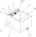
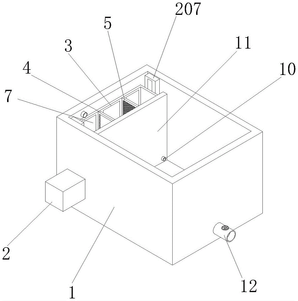
图1为本实用新型的结构示意图;Fig. 1 is the structural representation of the utility model;
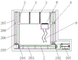
图2为本实用新型的剖视图;Fig. 2 is a sectional view of the utility model;
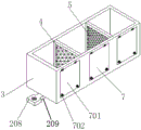
图3为本实用新型的过滤槽与仓门组件连接结构示意图;Fig. 3 is a schematic diagram of the connection structure between the filter tank and the door assembly of the present invention;
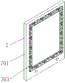
图4为本实用新型的仓门主体与密封垫圈连接结构示意图。Fig. 4 is a schematic diagram of the connection structure between the main body of the warehouse door and the sealing gasket of the present invention.
图中:1、处理池;2、升降组件;201、电机;202、第一锥型齿轮;203、传动轴;204、第二锥型齿轮;205、第三锥型齿轮;206、丝杆;207、外壳体;208、活动块;209、连接板;3、过滤槽;4、第一过滤板;5、第二过滤板;6、第三过滤板;7、仓门组件;701、仓门主体;702、固定螺栓;703、密封垫圈;8、缓冲槽;9、软管;10、连通管;11、隔板;12、排水管。In the figure: 1, treatment tank; 2, lifting assembly; 201, motor; 202, first bevel gear; 203, transmission shaft; 204, second bevel gear; 205, third bevel gear; 206, screw rod ; 207, the outer shell; 208, the movable block; 209, the connecting plate; 3, the filter tank; 4, the first filter plate; 5, the second filter plate; 6, the third filter plate; 7, the door assembly; 701, Main body of the warehouse door; 702, fixing bolts; 703, sealing gasket; 8, buffer tank; 9, flexible pipe; 10, connecting pipe; 11, clapboard;
具体实施方式Detailed ways
下面将结合本实用新型实施例中的附图,对本实用新型实施例中的技术方案进行清楚、完整地描述。下面通过参考附图描述的实施例是示例性的,仅用于解释本实用新型,而不能理解为对本实用新型的限制。The following will clearly and completely describe the technical solutions in the embodiments of the present invention with reference to the drawings in the embodiments of the present invention. The embodiments described below with reference to the accompanying drawings are exemplary and are only used to explain the present utility model, but should not be construed as limiting the present utility model.
下面根据本实用新型的整体结构,对其实施例进行说明。Below according to the overall structure of the utility model, its embodiment is described.
请参阅图1和图2,一种污水处理净化机构,包括处理池1,处理池1的内部安装有升降组件2,且升降组件2包括有电机201、第一锥型齿轮202、传动轴203、第二锥型齿轮204、第三锥型齿轮205、丝杆206、外壳体207、活动块208和连接板209,电机201位于处理池1的一侧设置,且第一锥型齿轮202位于电机201的输出端,传动轴203位于第一锥型齿轮202的一侧,且电机201外侧设置有电机保护罩,且电机201的输出端连接有蜗轮蜗杆减速器,且蜗轮蜗杆减速器通过联轴器与第一锥型齿轮202相连接,且第一锥型齿轮202与传动轴203之间相连接,且传动轴203外侧设置有多组支撑结构,第二锥型齿轮204位于传动轴203远离第一锥型齿轮202的一端,且第三锥型齿轮205的数量为两组,两组第三锥型齿轮205分别与第一锥型齿轮202与第二锥型齿轮204相啮合,以便于使传动轴203可以转动,且传动轴203与第二锥型齿轮204之间相连接,且第二锥型齿轮204与第一锥型齿轮202结构相同,且第三锥型齿轮205分别与第二锥型齿轮204和第一锥型齿轮202相匹配,且两组第三锥型齿轮205均设置有支撑结构,以便于使第三锥型齿轮205可以转动,丝杆206位于第三锥型齿轮205上方,且丝杆206顶端设置有轴承,轴承位于外壳体207内部,且外壳体207位于处理池1内壁设置,且丝杆206与第三锥型齿轮205之间相连接,且丝杆206位于外壳体207内部,活动块208位于丝杆206外侧设置,且活动块208内部开设有与丝杆206相匹配的螺孔,连接板209位于活动块208的一侧,且连接板209贯穿外壳体207并延伸至其外侧,且外壳体207一侧开设有缺口,且连接板209贯穿缺口并延伸至其外侧,且连接板209与过滤槽3之间焊接固定,通过设置的电机201、第一锥型齿轮202、传动轴203、第二锥型齿轮204、第三锥型齿轮205、丝杆206、外壳体207、活动块208和连接板209,实现便于带动过滤槽3移动,使过滤槽3移动至处理池1上表面,以便于工作人员对过滤槽3内部的杂质进行清理,通过电机201转动,使电机201带动第一锥型齿轮202转动第一锥型齿轮202带动传动轴203转动,传动轴203带动给第二锥型齿轮204转动,第二锥型齿轮204与第一锥型齿轮202转动带动第三锥型齿轮205转动,使第三锥型齿轮205转动带动给丝杆206转动,丝杆206转动带动活动块208移动,使活动块208移动带动过滤槽3移动。Please refer to Fig. 1 and Fig. 2, a sewage treatment and purification mechanism, including a
请参阅图1、图2、图3和图4,一种污水处理净化机构,连接板209上方设置有过滤槽3,且过滤槽3内部设置有第一过滤板4,第一过滤板4的一侧安装有第二过滤板5,且过滤槽3的底部设置有第三过滤板6,过滤槽3的一侧安装有仓门组件7,且仓门组件7包括有仓门主体701、固定螺栓702和密封垫圈703,第三过滤板6底部设置有缓冲槽8,且缓冲槽8底部连接有软管9,且第一过滤板4位于过滤槽3内部固定设置,且第二过滤板5位于过滤槽3内部固定设置,且第三过滤板6位于过滤槽3底部设置,且通过设置的第一过滤板4、第二过滤板5和第三过滤板6使污水内部的杂质可以更好的进行分级过滤,仓门主体701的一侧设置有合页,且仓门主体701与过滤槽3之间通过合页铰接转动,固定螺栓702位于仓门主体701的内部,且密封垫圈703位于仓门主体701的一侧,且设置的仓门主体701位于过滤槽3的一侧设置,使在需要对过滤槽3内部进行清理时,翻转仓门主体701使过滤槽3内部处于开启状态,以便于对过滤槽3内部的杂质进行处理,且通过设置固定螺栓702贯穿仓门主体701并延伸至其外侧,使固定螺栓702与过滤槽3内部开设的螺纹孔,螺纹连接固定,且设置的密封垫圈703具有较好的密封效果,可以使仓门主体701与过滤槽3接触得到位置不渗水,处理池1位于内部设置有隔板11,且软管9的一端连接有连通管10,连通管10贯穿隔板11并延伸至其外侧,且处理池1的一端开设有排水管12,且连通管10与软管9之间相连通,且连通管10内部安装有单向控制阀,新型通过设置的第一过滤板4、第二过滤板5和第三过滤板6,实现便于对污水内部的杂质进行分级过滤,以减少杂质过大造成滤网堵塞的情况出现,且通过设置的软管9与连通管10之间相连通,使经过过滤的污水沿着软管9至连通管10的方向流动,使过滤完的污水进入到处理池1的左侧,装置操作简单便捷,提高装置的灵活性。Please refer to Fig. 1, Fig. 2, Fig. 3 and Fig. 4, a sewage treatment and purification mechanism, a
工作原理:使用时,工作人员向处理池1内部通入生活污水,使污水进入到过滤槽3内部,后经过第一过滤板4的过滤使污水内部较大的杂质留在过滤槽3的左侧,后污水进入到第二过滤板5与第一过滤板4之间,后经过第二过滤板5的过滤,使污水中较小的杂质进行过滤,后污水进入到过滤槽3的右端,后经过第三过滤板6的过滤,使过滤完的污水进入到缓冲槽8内部,后经过软管9进入到连通管10内部,通过位于连通管10内部设置的单向阀,使污水流向处理池1的右侧,在需要对过滤槽3内部的杂质进行清理使,启动电机201,使电机201带动第一锥型齿轮202转动,第一锥型齿轮202转动带动传动轴203转动,传动轴203转动带动第二锥型齿轮204转动,第二锥型齿轮204转动带动第三锥型齿轮205转动给,第三锥型齿轮205转动带动丝杆206转动,丝杆206转动带动活动块208移动,使活动块208移动带动连接板209移动,使连接板209带动过滤槽3移动,使过滤槽3移动至合适位置,后转动固定螺栓702,翻转密封垫圈703,使过滤槽3的一侧处于开启状态,以便于对过滤槽3内部残留的杂质进行清理本说明书中未作详细描述的内容属于本领域专业技术人员公知的现有技术。Working principle: when in use, the staff feeds domestic sewage into the
术语“中心”、“纵向”、“横向”、“前”、“后”、“左”、“右”、“竖直”、“水平”、“顶”、“底”、“内”、“外”等指示的方位或位置关系为基于附图所示的方位或位置关系,仅是为便于描述本实用新型的简化描述,而不是指示或暗指所指的装置或元件必须具有特定的方位、为特定的方位构造和操作,因而不能理解为对本实用新型保护内容的限制。The terms "center", "portrait", "landscape", "front", "rear", "left", "right", "vertical", "horizontal", "top", "bottom", "inner", The orientation or positional relationship indicated by "outside" is based on the orientation or positional relationship shown in the drawings, and is only for the convenience of describing the simplified description of the present utility model, rather than indicating or implying that the referred device or element must have a specific Orientation is a specific orientation structure and operation, so it cannot be interpreted as a limitation on the protection content of the present utility model.
尽管参照前述实施例对本实用新型进行了详细的说明,对于本领域的技术人员来说,其依然可以对前述各实施例所记载的技术方案进行修改,或者对其中部分技术特征进行等同替换,凡在本实用新型的精神和原则之内,所作的任何修改、等同替换、改进等,均应包含在本实用新型的保护范围之内。Although the utility model has been described in detail with reference to the aforementioned embodiments, those skilled in the art can still modify the technical solutions described in the aforementioned embodiments, or perform equivalent replacements for some of the technical features. Within the spirit and principles of the utility model, any modification, equivalent replacement, improvement, etc., should be included in the protection scope of the utility model.
Claims (7)
Priority Applications (1)
| Application Number | Priority Date | Filing Date | Title |
|---|---|---|---|
| CN202320690199.XU CN219333396U (en) | 2023-03-31 | 2023-03-31 | Sewage treatment purifying mechanism |
Applications Claiming Priority (1)
| Application Number | Priority Date | Filing Date | Title |
|---|---|---|---|
| CN202320690199.XU CN219333396U (en) | 2023-03-31 | 2023-03-31 | Sewage treatment purifying mechanism |
Publications (1)
| Publication Number | Publication Date |
|---|---|
| CN219333396U true CN219333396U (en) | 2023-07-14 |
Family
ID=87103295
Family Applications (1)
| Application Number | Title | Priority Date | Filing Date |
|---|---|---|---|
| CN202320690199.XU Active CN219333396U (en) | 2023-03-31 | 2023-03-31 | Sewage treatment purifying mechanism |
Country Status (1)
| Country | Link |
|---|---|
| CN (1) | CN219333396U (en) |
-
2023
- 2023-03-31 CN CN202320690199.XU patent/CN219333396U/en active Active
Similar Documents
| Publication | Publication Date | Title |
|---|---|---|
| CN218011316U (en) | Rural integration filter | |
| CN117602704A (en) | Sewage treatment tank scum collecting device and using method thereof | |
| CN210251406U (en) | Chemical waste liquid filter equipment | |
| CN112340885A (en) | Domestic sewage centralized pre-filtering equipment and using method thereof | |
| CN112777786A (en) | High-efficiency energy-saving sewage draining environment-friendly device | |
| CN215427564U (en) | Automatic sewage discharging device for sewage treatment | |
| CN214485888U (en) | Sewage filter system | |
| CN219783941U (en) | Wastewater floccule filtering and purifying device | |
| CN218011439U (en) | Filter plate cleaning mechanism for wastewater treatment | |
| CN219489746U (en) | Aeration device | |
| CN220495700U (en) | A kind of recycled water recycling and filtration device | |
| CN218058668U (en) | A new energy rural sewage treatment integrated equipment | |
| CN218713630U (en) | Liquid is filtration purification device for kitchen garbage | |
| CN220537653U (en) | Rural sewage treatment plant | |
| CN211462238U (en) | A sewage treatment tank that does not block the sewage filtration | |
| CN213294892U (en) | Green building sewage treatment device | |
| CN211285906U (en) | Energy-saving building water supply and drainage device that takes into account overflow prevention and impurity filtration | |
| CN210302655U (en) | Energy-saving emission-reducing sewage treatment equipment | |
| CN217855389U (en) | High concentration acid mist waste gas purification tower | |
| CN218622552U (en) | Sewage treatment is with preventing stifled device | |
| CN216725962U (en) | Low energy consumption sewage treatment system based on energy conservation and environmental protection | |
| CN222477614U (en) | A reclaimed water supply device | |
| CN221894758U (en) | Sewage treatment back flush device | |
| CN216798870U (en) | Unpowered backflow integrated sewage treatment equipment | |
| CN219897288U (en) | Sewage pipe discharging device for sewage treatment |
Legal Events
| Date | Code | Title | Description |
|---|---|---|---|
| GR01 | Patent grant | ||
| GR01 | Patent grant | ||
| CP03 | Change of name, title or address | ||
| CP03 | Change of name, title or address |
Address after: 030000 Shanxi Province Taiyuan City Shanxi Transformation and Comprehensive Reform Demonstration Zone Xuefu Industrial Park Pingyang Road 137 Jinrun International Building B 10th Floor 1001 Room Patentee after: Shanxi Ruichengda Huanneng Technology Co.,Ltd. Country or region after: China Address before: 030006 room 1001, 10 / F, block B, Jinrun international, No. 139, Pingyang Road, Taiyuan Xuefu Park, Shanxi comprehensive reform demonstration zone, Taiyuan City, Shanxi Province Patentee before: Shanxi ruichengda Shenghuan Technology Co.,Ltd. Country or region before: China |