CN219324293U - A feeding device for crushing copper-nickel massive slag minerals - Google Patents
A feeding device for crushing copper-nickel massive slag minerals Download PDFInfo
- Publication number
- CN219324293U CN219324293U CN202320452824.7U CN202320452824U CN219324293U CN 219324293 U CN219324293 U CN 219324293U CN 202320452824 U CN202320452824 U CN 202320452824U CN 219324293 U CN219324293 U CN 219324293U
- Authority
- CN
- China
- Prior art keywords
- discharging
- vibration
- control
- storage bin
- bin
- Prior art date
- Legal status (The legal status is an assumption and is not a legal conclusion. Google has not performed a legal analysis and makes no representation as to the accuracy of the status listed.)
- Active
Links
- 239000002893 slag Substances 0.000 title claims abstract description 28
- 229910052500 inorganic mineral Inorganic materials 0.000 title claims abstract description 19
- 239000011707 mineral Substances 0.000 title claims abstract description 19
- 229910000570 Cupronickel Inorganic materials 0.000 title claims abstract description 14
- YOCUPQPZWBBYIX-UHFFFAOYSA-N copper nickel Chemical compound [Ni].[Cu] YOCUPQPZWBBYIX-UHFFFAOYSA-N 0.000 title claims abstract description 14
- 238000007599 discharging Methods 0.000 claims abstract description 36
- 238000007664 blowing Methods 0.000 claims 1
- PXHVJJICTQNCMI-UHFFFAOYSA-N Nickel Chemical compound [Ni] PXHVJJICTQNCMI-UHFFFAOYSA-N 0.000 abstract description 9
- 239000010949 copper Substances 0.000 abstract description 7
- RYGMFSIKBFXOCR-UHFFFAOYSA-N Copper Chemical compound [Cu] RYGMFSIKBFXOCR-UHFFFAOYSA-N 0.000 abstract description 6
- 229910052802 copper Inorganic materials 0.000 abstract description 6
- 229910052759 nickel Inorganic materials 0.000 abstract description 5
- 230000001276 controlling effect Effects 0.000 abstract 1
- 230000001105 regulatory effect Effects 0.000 abstract 1
- 238000003723 Smelting Methods 0.000 description 4
- 239000000463 material Substances 0.000 description 4
- 238000010586 diagram Methods 0.000 description 3
- 238000000034 method Methods 0.000 description 3
- 239000002245 particle Substances 0.000 description 3
- 238000004519 manufacturing process Methods 0.000 description 2
- 239000000725 suspension Substances 0.000 description 2
- 239000004615 ingredient Substances 0.000 description 1
- 238000009434 installation Methods 0.000 description 1
- 229910052751 metal Inorganic materials 0.000 description 1
- 239000002184 metal Substances 0.000 description 1
- 150000002739 metals Chemical class 0.000 description 1
- 238000009856 non-ferrous metallurgy Methods 0.000 description 1
- 238000009853 pyrometallurgy Methods 0.000 description 1
- 239000002994 raw material Substances 0.000 description 1
Images
Classifications
-
- Y—GENERAL TAGGING OF NEW TECHNOLOGICAL DEVELOPMENTS; GENERAL TAGGING OF CROSS-SECTIONAL TECHNOLOGIES SPANNING OVER SEVERAL SECTIONS OF THE IPC; TECHNICAL SUBJECTS COVERED BY FORMER USPC CROSS-REFERENCE ART COLLECTIONS [XRACs] AND DIGESTS
- Y02—TECHNOLOGIES OR APPLICATIONS FOR MITIGATION OR ADAPTATION AGAINST CLIMATE CHANGE
- Y02P—CLIMATE CHANGE MITIGATION TECHNOLOGIES IN THE PRODUCTION OR PROCESSING OF GOODS
- Y02P10/00—Technologies related to metal processing
- Y02P10/20—Recycling
Landscapes
- Manufacture And Refinement Of Metals (AREA)
Abstract
Description
技术领域technical field
本实用新型属于有色冶金技术领域,具体是一种用于破碎铜镍块状炉渣矿物的放料装置。The utility model belongs to the technical field of nonferrous metallurgy, in particular to a feeding device for crushing copper-nickel massive slag minerals.
背景技术Background technique
含铜镍原料有色火法冶炼过程中铜熔炼产生的铜渣铜镍含量高,一般为Cu 9.13~30.97%、Ni 4.40~18.11%。为进一步回收提取铜镍有价金属,需对铜渣破碎至10-15mm以达到再次火法配料冶炼的要求,具体为:先将炉底渣包中的铜渣经重锤砸裂成直径300-500mm的大块渣,然后经颚式破碎机破碎成直径100-200mm的块状炉渣矿物,最后至炉渣破碎的关键环节。Copper-nickel-containing raw materials The copper-nickel slag produced by copper smelting during the colored pyrometallurgical smelting process has a high content of copper and nickel, generally Cu 9.13-30.97%, Ni 4.40-18.11%. In order to further recover and extract the valuable metals of copper and nickel, it is necessary to crush the copper slag to 10-15mm to meet the requirements of the pyrochemical batching smelting again. -500mm bulk slag, and then crushed into massive slag minerals with a diameter of 100-200mm by the jaw crusher, and finally to the key link of slag crushing.
上述炉渣破碎的关键环节是指,通过铲运机将100-200mm块状炉渣矿物加入料仓,经由皮带运输机输送至棒磨机破碎至10-20mm粒径大小,以符合火法冶炼配料要求的粒度。但在实际生产中,直径100-200mm块状炉渣矿物在料仓中易出现蓬结或放料不畅的问题,而如果加大料仓放料口尺寸,会导致出料量过多,无法保证棒磨机对炉渣物料的破碎粒度,不能满足配料冶炼生产需要。The key link of the above-mentioned slag crushing refers to adding 100-200mm massive slag minerals into the silo through the scraper, and transporting them to the rod mill through the belt conveyor for crushing to a particle size of 10-20mm, so as to meet the requirements of pyrometallurgy ingredients. granularity. However, in actual production, blocky slag minerals with a diameter of 100-200mm are prone to problems such as puffiness or poor discharge in the silo, and if the size of the discharge port of the silo is increased, the discharge volume will be too much and cannot be discharged. Ensuring the crushing particle size of the slag material by the rod mill cannot meet the needs of batching smelting production.
实用新型内容Utility model content
本实用新型的目的在于提供一种用于破碎铜镍块状炉渣矿物的放料装置,以解决块状炉渣矿物在现有料仓中易出现蓬结或放料不畅,而加大现有料仓放料口尺寸无法保证炉渣物料破碎粒度的技术问题。The purpose of the utility model is to provide a feeding device for crushing copper-nickel massive slag minerals, so as to solve the problem that the massive slag minerals are prone to clumps or unsmooth discharging in the existing silos, and the existing silos are enlarged. The size of the discharge port cannot guarantee the technical problem of the crushing particle size of the slag material.
为实现其目的,本实用新型采用如下技术方案:For realizing its purpose, the utility model adopts following technical scheme:
一种用于破碎铜镍块状炉渣矿物的放料装置,包括料仓,所述料仓包括一体成型的料仓进料口和料仓出料口,所述料仓出料口底部设有振动卸料槽,振动卸料槽充当料仓底板,该振动卸料槽一侧设有振动马达;料仓出料口一侧通过旋转轴设有放料开度控制板,放料开度控制板底部与振动卸料槽上表面相接触,放料开度控制板外侧与控制四连杆一端相接,控制四连杆中段活动连接于门型固定架横部,控制四连杆另一端设有固定插销;所述门型固定架任一纵部设有卡槽组,固定插销与卡槽组卡槽相配合控制放料开度控制板开度。A discharge device for crushing copper-nickel massive slag minerals, comprising a silo, the silo includes an integrally formed silo inlet and a silo outlet, the bottom of the hopper outlet is provided with Vibration unloading chute, the vibrating unloading chute acts as the bottom plate of the silo, the side of the vibrating unloading chute is equipped with a vibration motor; The bottom of the plate is in contact with the upper surface of the vibrating unloading chute, the outer side of the discharge opening control plate is connected with one end of the control four-linkage, the middle section of the control four-linkage is movably connected to the horizontal part of the door-type fixed frame, and the other end of the control four-linkage is set There is a fixed bolt; any longitudinal part of the door-type fixed frame is provided with a card slot group, and the fixed bolt cooperates with the card slot group to control the opening of the material discharge control panel.
作为本实用新型技术方案的进一步改进,所述料仓出料口外周设有料仓固定架,振动卸料槽通过振动弹簧与料仓固定架连接。As a further improvement of the technical solution of the utility model, a bin fixing frame is provided on the outer periphery of the outlet of the bin, and the vibrating unloading trough is connected with the bin fixing frame through a vibrating spring.
进一步地,所述振动卸料槽边缘与振动弹簧悬挂式柔性连接,下料时,振动卸料槽沿料仓出料口向下倾斜6-10°。Further, the edge of the vibrating unloading chute is flexibly connected to the vibrating spring suspension, and when unloading, the vibrating unloading chute is inclined downward by 6-10° along the outlet of the silo.
进一步地,所述振动弹簧通过螺栓与料仓固定架相连。Further, the vibrating spring is connected with the bin fixing frame through bolts.
进一步地,所述控制四连杆中段通过连杆固定管活动连接于门型固定架横部。Further, the middle section of the control four-bar linkage is movably connected to the transverse part of the door-shaped fixing frame through the link fixing pipe.
进一步地,所述连杆固定管固接于门型固定架横部内侧,控制四连杆中段穿过该连杆固定管。Further, the connecting rod fixing pipe is fixedly connected to the inner side of the transverse part of the door-shaped fixing frame, and the middle section of the four-link control rod passes through the connecting rod fixing pipe.
本实用新型通过改变固定插销在卡槽组中插槽的位置,由控制四连杆控制放料控制板开度大小,并调节振动马达频率,通过曲臂杠杆原理和震动原理简便控制放料量大小。其结构简单精巧,易于操作,成功解决了铜镍大小不均块状炉渣破碎时料仓出料易蓬结或放料不畅的卡脖子问题。The utility model changes the slot position of the fixed bolt in the slot group, controls the opening of the discharge control plate by controlling the four-linkage bar, and adjusts the frequency of the vibration motor, and controls the discharge amount simply and conveniently through the crank arm lever principle and the vibration principle. size. Its structure is simple and exquisite, and it is easy to operate. It successfully solves the neck problem that the discharge of the silo is easy to clump or the discharge is not smooth when the lumpy slag with uneven size of copper and nickel is broken.
附图说明Description of drawings
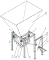
图1为本实用新型放料装置的结构示意图;Fig. 1 is the structural representation of the utility model discharging device;
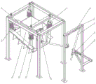
图2为本实用新型放料装置的局部结构示意图;Fig. 2 is a partial structural schematic diagram of the utility model discharging device;
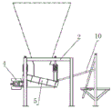
图3为振动马达和振动卸料槽及连杆的安装位置示意图;Fig. 3 is a schematic diagram of the installation positions of the vibrating motor, the vibrating unloading chute and the connecting rod;
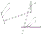
图4 为控制四连杆的结构示意图;Figure 4 is a schematic diagram of the structure of the control four-linkage;
附图标记:1、振动马达;2、料仓固定架;3、料仓出料口;4、振动弹簧;5、悬挂式料仓底板振动卸料槽;6、放料开度控制板;7、旋转轴;8、连杆固定管;9、门型连杆固定架;10、控制四连杆;11、固定插销;12、卡槽组;13、料仓进料口。Reference signs: 1. Vibrating motor; 2. Bin fixing frame; 3. Bin outlet; 4. Vibrating spring; 5. Suspended bin bottom plate vibrating unloading chute; 6. Discharging opening control panel; 7. Rotary shaft; 8. Connecting rod fixing tube; 9. Door-type connecting rod fixing frame; 10. Control four-link; 11. Fixed bolt; 12. Card slot group;
具体实施方式Detailed ways
下面结合附图对本实用新型的结构和工作过程进行详细说明。Below in conjunction with accompanying drawing, structure and working process of the present utility model are described in detail.
参照图1-4,本实用新型公开的一种用于破碎铜镍块状炉渣矿物的放料装置,包括料仓,所述料仓包括一体成型的料仓进料口13和料仓出料口3,料仓出料口3外周设有料仓固定架2,所述料仓出料口3底部设有振动卸料槽5,振动卸料槽5充当料仓底板,振动卸料槽5边缘通过振动弹簧4与料仓固定架2悬挂式柔性连接,振动弹簧4通过螺栓与料仓固定架2相连,该振动卸料槽5一侧还设有振动马达1;料仓出料口3一侧通过旋转轴7设有放料开度控制板6,放料开度控制板6底部与振动卸料槽5上表面相接触,放料开度控制板6外侧与控制四连杆10一端相接,控制四连杆10中段通过连杆固定管8活动连接于门型固定架9横部,具体的,所述连杆固定管8固接于门型固定架9横部内侧,控制四连杆10中段穿过该连杆固定管8,控制四连杆10另一端设有固定插销11;所述门型固定架9任一纵部设有卡槽组12,固定插销11与卡槽组12卡槽相配合控制放料开度控制板6开度。Referring to Figures 1-4, the utility model discloses a discharge device for crushing copper-nickel massive slag minerals, including a silo, which includes an integrally formed
工作时,铲运机将100-200mm块状炉渣矿物从料仓进料口13加入后,启动后段皮带运输机、棒磨机破碎设备,然后启动振动马达1。当炉渣矿物通过料仓出料口3至振动卸料槽5时,振动卸料槽5沿料仓出料口3向下倾斜6-10°,通过调整振动马达1的振动频率,使炉渣矿物沿振动卸料槽5滑落至靠近放料开度控制板6位置;手动操作控制四连杆10插销端,通过曲臂杠杆原理控制放料开度控制板6开度来控制放料量,当放料量稳定后,将固定插销11插入卡槽组对应卡槽进行放料。During work, after the scraper adds 100-200mm lumpy slag minerals from the
Claims (6)
Priority Applications (1)
| Application Number | Priority Date | Filing Date | Title |
|---|---|---|---|
| CN202320452824.7U CN219324293U (en) | 2023-03-11 | 2023-03-11 | A feeding device for crushing copper-nickel massive slag minerals |
Applications Claiming Priority (1)
| Application Number | Priority Date | Filing Date | Title |
|---|---|---|---|
| CN202320452824.7U CN219324293U (en) | 2023-03-11 | 2023-03-11 | A feeding device for crushing copper-nickel massive slag minerals |
Publications (1)
| Publication Number | Publication Date |
|---|---|
| CN219324293U true CN219324293U (en) | 2023-07-11 |
Family
ID=87065200
Family Applications (1)
| Application Number | Title | Priority Date | Filing Date |
|---|---|---|---|
| CN202320452824.7U Active CN219324293U (en) | 2023-03-11 | 2023-03-11 | A feeding device for crushing copper-nickel massive slag minerals |
Country Status (1)
| Country | Link |
|---|---|
| CN (1) | CN219324293U (en) |
Cited By (1)
| Publication number | Priority date | Publication date | Assignee | Title |
|---|---|---|---|---|
| CN116237145A (en) * | 2023-03-11 | 2023-06-09 | 金川集团股份有限公司 | A feeding device for crushing copper-nickel massive slag minerals |
-
2023
- 2023-03-11 CN CN202320452824.7U patent/CN219324293U/en active Active
Cited By (1)
| Publication number | Priority date | Publication date | Assignee | Title |
|---|---|---|---|---|
| CN116237145A (en) * | 2023-03-11 | 2023-06-09 | 金川集团股份有限公司 | A feeding device for crushing copper-nickel massive slag minerals |
Similar Documents
| Publication | Publication Date | Title |
|---|---|---|
| CN111760642A (en) | Chain crusher for biological organic fertilizer | |
| CN219193574U (en) | High-efficient complete sets production facility of metal silica flour | |
| CN202155307U (en) | Vibration feeding and screening equipment | |
| CN217431902U (en) | A feed crushing system | |
| CN202983825U (en) | Salt-leaching system | |
| CN212349064U (en) | A new type of perlite sand production line | |
| CN116237145A (en) | A feeding device for crushing copper-nickel massive slag minerals | |
| CN119406554A (en) | An ore crusher feeding system with iron recognition and picking function | |
| CN219984931U (en) | Technological device for solving raw material receiving and grading | |
| CN207823108U (en) | A device for preventing secondary crushing of petroleum coke fines | |
| CN213914258U (en) | Cement production raw meal grinds feed arrangement immediately | |
| CN209753097U (en) | Sand making unit | |
| CN209997675U (en) | jaw crusher for waste tailing treatment | |
| CN108722541B (en) | Broken shot blasting system of return burden | |
| CN207913925U (en) | One stage crushing magnetic separation all-in-one machine | |
| CN221016189U (en) | Broken screening all-in-one in jaw | |
| CN223171029U (en) | Broken screening production line of metal lump material | |
| CN221459012U (en) | Ore feeding device suitable for various lithium ores | |
| CN207735340U (en) | Processing apparatus of electric smelting magnesium returning charge | |
| CN220861618U (en) | Self-cleaning device for vertical mill central tube | |
| CN207951693U (en) | A kind of special bulky grain recycling lifting device of standing crusher | |
| CN206580330U (en) | A kind of lump material batcher | |
| CN221156387U (en) | Dry process powder process compounding equipment of iron ore | |
| CN215743786U (en) | Feeding mechanism of crusher | |
| CN217599884U (en) | Bottom unloading system for semi-finished product warehouse of large-scale machine-made sand aggregate factory |
Legal Events
| Date | Code | Title | Description |
|---|---|---|---|
| GR01 | Patent grant | ||
| GR01 | Patent grant | ||
| TR01 | Transfer of patent right |
Effective date of registration: 20240223 Address after: 737100 No. 2 Lanzhou Road, Beijing Road Street, Jinchuan District, Jinchang City, Gansu Province Patentee after: Jinchuan Group Nickel Cobalt Co.,Ltd. Country or region after: China Address before: 737103 No. 98, Jinchuan Road, Jinchang, Gansu Patentee before: JINCHUAN GROUP Co.,Ltd. Country or region before: China |
|
| TR01 | Transfer of patent right | ||
| CP03 | Change of name, title or address |
Address after: No. 31 Beijing Road, Beijing Road Street, Jinchuan District, Jinchang City, Gansu Province 737100 Patentee after: Jinchuan Group Nickel Cobalt Co.,Ltd. Country or region after: China Address before: No. 2 Lanzhou Road, Beijing Road Street, Jinchuan District, Jinchang City, Gansu Province Patentee before: Jinchuan Group Nickel Cobalt Co.,Ltd. Country or region before: China |
|
| CP03 | Change of name, title or address |