CN219310455U - Support assembly welding tool convenient to operate and stable in welding quality - Google Patents
Support assembly welding tool convenient to operate and stable in welding quality Download PDFInfo
- Publication number
- CN219310455U CN219310455U CN202222873848.8U CN202222873848U CN219310455U CN 219310455 U CN219310455 U CN 219310455U CN 202222873848 U CN202222873848 U CN 202222873848U CN 219310455 U CN219310455 U CN 219310455U
- Authority
- CN
- China
- Prior art keywords
- base
- welding
- main
- pressing device
- pressing
- Prior art date
- Legal status (The legal status is an assumption and is not a legal conclusion. Google has not performed a legal analysis and makes no representation as to the accuracy of the status listed.)
- Expired - Fee Related
Links
Images


Landscapes
- Resistance Welding (AREA)
Abstract
本实用新型公开了一种操作方便焊接质量稳定的支架组装焊接工装,包括焊接底座、焊接工位一及焊接工位二,所述焊接工位一及焊接工位二分别对称设置在焊接底座的两端,所述焊接工位一及焊接工位二是相同结构,所述焊接工位一由主压紧装置、侧压紧装置及辅助压紧装置组成,通过支架焊接工装使汽车支架的各部件能精准的组合,能一次将支架的所有部件组焊,焊接成品率高,而且该工装结构简单,操作方便。通过支架焊接工装生产出的产品尺寸稳定且符合图纸要求,大大提高了效率及产品质量的稳定性在焊接生产时可同时进行两个支架的组装焊接,一人进行组装一人进行焊接,焊接完成后拆卸在进行组装,操作人员均有自己的分工,焊接效率高。
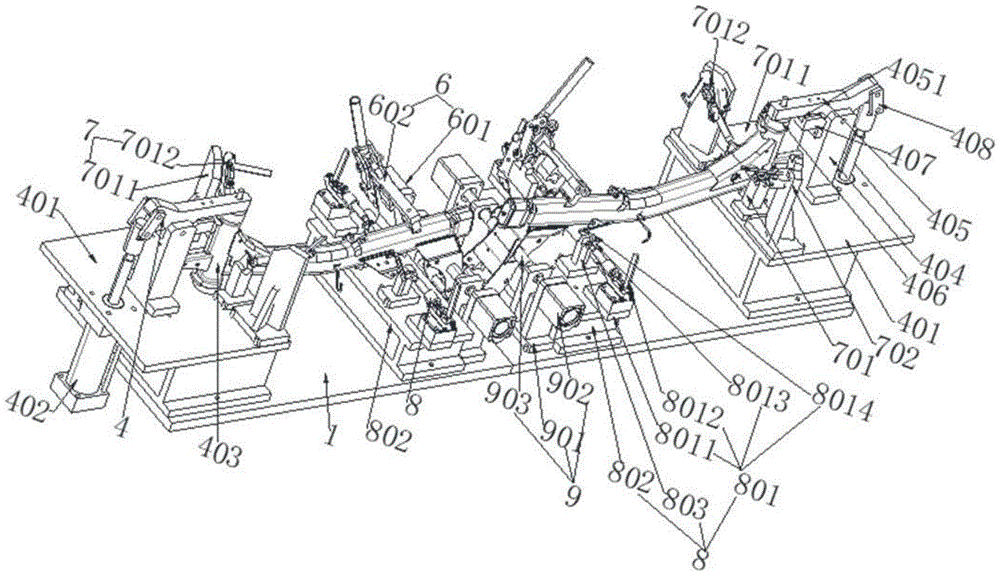
The utility model discloses a bracket assembly welding tool with convenient operation and stable welding quality, which comprises a welding base, a welding station 1 and a welding station 2, and the welding station 1 and the welding station 2 are symmetrically arranged on the welding base respectively. Both ends, the welding station one and welding station two are the same structure, the welding station one is made up of the main pressing device, the side pressing device and the auxiliary pressing device. The parts can be assembled precisely, all the parts of the bracket can be assembled and welded at one time, the welding yield is high, and the tooling has a simple structure and is easy to operate. The size of the product produced by the bracket welding tool is stable and meets the requirements of the drawing, which greatly improves the efficiency and the stability of product quality. During welding production, two brackets can be assembled and welded at the same time, one person assembles and the other welds, and disassembles after welding. During assembly, operators have their own division of labor, and the welding efficiency is high.
Description
技术领域technical field
本实用新型涉及机械焊接加工的技术领域,特别涉及一种操作方便焊接质量稳定的支架组装焊接工装。The utility model relates to the technical field of mechanical welding processing, in particular to a bracket assembly welding tool with convenient operation and stable welding quality.
背景技术Background technique
汽车支架是由N多种工件通过焊接的方式制作而成,焊接工艺复杂,现有汽车支架焊接为局部焊接,即将整个支架分开通过人工先将部分工件组合焊接成N多焊接小组件,然后再通过人工将这些焊接小组件在组合焊接,最终完成支架的整体焊接,由于汽车支架工零部件种类较多,采用这种焊接工艺焊接工序多,焊接存在差异,存在累积误差,会导致支架焊接尺寸满足不了图纸要求,存在质量隐患,且焊接效率低。The car bracket is made of N kinds of workpieces by welding. The welding process is complicated. The existing car bracket is welded as local welding, that is, the whole bracket is separated and manually welded into N multi-welding small components, and then By manually welding these welding small components together, the overall welding of the bracket is finally completed. Since there are many types of auto bracket parts, this welding process has many welding processes, there are differences in welding, and there are cumulative errors, which will lead to the welding size of the bracket. It cannot meet the requirements of the drawings, there are quality risks, and the welding efficiency is low.
因此需要提供一种操作方便焊接质量稳定的支架组装焊接工装来解决上述技术问题。Therefore, it is necessary to provide a bracket assembly welding tool with convenient operation and stable welding quality to solve the above technical problems.
实用新型内容Utility model content
本实用新型的目的在于解决现有铝铸三角形支架在进行镗孔加工时的固定装夹一般有多个定位销及多个固定夹紧装置组成,操作复杂,这种操作方式,效率较低,不适合批量生产这一技术问题,提供一种操作方便焊接质量稳定的支架组装焊接工装来解决上述技术问题。The purpose of this utility model is to solve the problem that the fixed clamping of the existing aluminum-cast triangular brackets during boring processing is generally composed of multiple positioning pins and multiple fixed clamping devices, and the operation is complicated. This operation mode has low efficiency. It is not suitable for the technical problem of mass production, and a bracket assembly welding tool with convenient operation and stable welding quality is provided to solve the above technical problem.
为实现前述实用新型目的,本实用新型采用的技术方案:一种操作方便焊接质量稳定的支架组装焊接工装,其特征在于:包括焊接底座、焊接工位一及焊接工位二,所述焊接工位一及焊接工位二分别对称设置在焊接底座的两端,所述焊接工位一及焊接工位二是相同结构,所述焊接工位一由主压紧装置、侧压紧装置及辅助压紧装置组成,所述侧压紧装置由两个A侧压装置、两个B侧压装置及两个C侧压装置组成,两个A侧压装置对称设置在焊接底座的两侧长边框内且靠近焊接底座短边框一端,两个B侧压装置对称设置在焊接底座的两侧长边框内,两个C侧压装置对称设置在焊接底座的两侧长边框内,两个C侧压装置设置在焊接底座的中间位置,两个B侧压装置靠近C侧压装置,所述主压紧装置设置在焊接底座的短边框的端部,所述辅助压紧装置设置在焊接底座的中间的一侧长边框内,且位于同侧B侧压装置与C侧压装置之间,所述主压紧装置由主底座、主气缸、定位柱、主支撑架、主压板、主压头、主限位槽及连接件组成,所述A侧压装置由A压紧装置及A工件放置块组成,所述A压紧装置由A底座及A肘夹组成,所述A工件放置块设置在A压紧装置的前方,所述B侧压装置由B压紧装置、B底座及B工件放置块组成,所述B压紧装置由B压紧底座、B肘夹、B压板及B压杆组成,所述B工件放置块设置在B压紧装置的前方,所述C侧压装置由C底座、C气缸及C压杆组成,所述辅助压紧装置由D底座及D压紧装置组成,所述D压紧装置由D连接杆、D压头、D压杆、D底座、D活动连接板、D活动连接块、L型连接板、连接条及圆轴组成。In order to achieve the purpose of the aforementioned utility model, the technical solution adopted by the utility model is: a bracket assembly welding tool with convenient operation and stable welding quality, which is characterized in that it includes a welding base, welding station 1 and welding station 2, and the welding station The first welding station and the second welding station are symmetrically arranged at the two ends of the welding base respectively. The first welding station and the second welding station have the same structure. The first welding station is composed of a main pressing device, a side pressing device and an auxiliary The side pressing device is composed of two A side pressing devices, two B side pressing devices and two C side pressing devices, and the two A side pressing devices are symmetrically arranged on the long frames on both sides of the welding base Inside and close to one end of the short frame of the welding base, two B side pressure devices are symmetrically arranged in the long frames on both sides of the welding base, two C side pressure devices are symmetrically arranged in the two side long frames of the welding base, and two C side pressure devices The device is set in the middle of the welding base, and the two B side pressing devices are close to the C side pressing device, the main pressing device is set at the end of the short frame of the welding base, and the auxiliary pressing device is set in the middle of the welding base In the long frame of one side, and between the B side pressure device and the C side pressure device on the same side, the main pressure device consists of a main base, a main cylinder, a positioning column, a main support frame, a main pressure plate, a main pressure head, The A side pressing device is composed of the A pressing device and the A workpiece placing block, the A pressing device is composed of the A base and the A elbow clamp, and the A workpiece placing block is set on In front of the A pressing device, the B side pressing device is composed of the B pressing device, the B base and the B workpiece placement block, and the B pressing device is composed of the B pressing base, the B toggle clamp, the B pressing plate and the B pressing rod Composition, the B workpiece placement block is set in front of the B pressing device, the C side pressing device is composed of a C base, a C cylinder and a C pressing rod, and the auxiliary pressing device is composed of a D base and a D pressing device , the D compression device is composed of a D connecting rod, a D pressure head, a D pressure rod, a D base, a D movable connecting plate, a D movable connecting block, an L-shaped connecting plate, a connecting bar and a round shaft.
进一步的,所述主底座固定在焊接底座短边框一端,所述主气缸固定在主底座的下方,主气缸的输出轴穿过主底座与主压板通过连接件活动连接,连接件一端与气缸的输出轴活动连接,另一端与主压板活动连接,所述主支撑架设置在主气缸输出轴的正前方的主底座上,所述主限位槽设置在主支撑架的远离主气缸输出轴的一侧的上部,所述主压板的底部设有凸块,所述凸块与主限位槽相匹配,凸块可以卡接在主限位槽内,所述定位柱组装在主底座上并且位于主支撑架的正前方,所述主压板靠近定位柱的一端的下方组装由主压头,所述主压头及定位柱为圆柱形结构。Further, the main base is fixed on one end of the short frame of the welding base, the main cylinder is fixed under the main base, the output shaft of the main cylinder passes through the main base and is connected to the main pressure plate through a connecting piece, and one end of the connecting piece is connected to the cylinder. The output shaft is movably connected, and the other end is movably connected with the main pressure plate. The main support frame is arranged on the main base directly in front of the output shaft of the master cylinder. On the upper part of one side, the bottom of the main pressure plate is provided with a protrusion, the protrusion matches the main limiting groove, the protrusion can be snapped into the main limiting groove, the positioning column is assembled on the main base and Located directly in front of the main support frame, the main pressure head is assembled under the end of the main pressure plate close to the positioning column, and the main pressure head and the positioning column are cylindrical structures.
进一步的,所述A侧压装置固定在主底座上,所述A肘夹固定在A底座的上部,所述A肘夹与水平的夹角为45°,所述A肘夹由肘夹座、条形连接杆、把手及夹紧杆组成,所述把手同时与条形连接杆及肘夹座活动连接,条形连接杆与夹紧杆活动连接。Further, the side pressure device A is fixed on the main base, the elbow clamp A is fixed on the upper part of the base A, the angle between the elbow clamp A and the horizontal is 45°, and the elbow clamp A is supported by the toggle clamp seat , a bar-shaped connecting rod, a handle and a clamping rod, the handle is movably connected with the bar-shaped connecting rod and the elbow clamp seat at the same time, and the bar-shaped connecting rod is movably connected with the clamping rod.
进一步的,所述B压紧装置及B工件放置块固定在B底座上,所述B底座固定在焊接底座上,所述B压紧底座固定在B底座上,所述B肘夹与A肘夹的结构相同,所述B压板与B肘夹固定连接,所述B压杆与B压板固定连接。Further, the B pressing device and the B workpiece placement block are fixed on the B base, the B base is fixed on the welding base, the B pressing base is fixed on the B base, and the B elbow clamp and A elbow The clamps have the same structure, the B pressing plate is fixedly connected to the B toggle clamp, and the B pressing bar is fixedly connected to the B pressing plate.
进一步的,所述C侧压装置通过C底座固定在焊接底座上,所述C气缸固定在C底座一侧,所述C气缸的输出轴穿过C底座与C压杆连接组装。Further, the C side pressure device is fixed on the welding base through the C base, the C cylinder is fixed on one side of the C base, and the output shaft of the C cylinder passes through the C base and is connected to the C pressure rod for assembly.
进一步的,所述D底座固定在B底座上,所述D活动连接块一端固定在D底座上,另一端与L型连接板及D活动连接板活动连接,所述D连接杆的一端与D活动连接板连接,另一端的下方固定连接D压头,所述D压头设有槽,在实际操作过程中通过槽进行固定压紧工件,所述D压杆通过连接条及圆轴与D活动连接板活动连接。Further, the D base is fixed on the B base, one end of the D movable connection block is fixed on the D base, and the other end is movably connected with the L-shaped connecting plate and the D movable connecting plate, and one end of the D connecting rod is connected with the D The movable connecting plate is connected, and the bottom of the other end is fixedly connected to the D pressure head. The D pressure head is provided with a groove, and the workpiece is fixed and pressed through the groove during the actual operation. Active Links Active Links.
与现有技术相比,本实用新型的优点包括:通过支架焊接工装使汽车支架的各部件能精准的组合,能一次将支架的所有部件组焊,焊接成品率高,而且该工装结构简单,操作方便。通过支架焊接工装生产出的产品尺寸稳定且符合图纸要求,大大提高了效率及产品质量的稳定性在焊接生产时可同时进行两个支架的组装焊接,一人进行组装一人进行焊接,焊接完成后拆卸在进行组装,操作人员均有自己的分工,焊接效率高。Compared with the prior art, the utility model has the advantages of: through the bracket welding tool, the parts of the car bracket can be assembled accurately, all the parts of the bracket can be assembled and welded at one time, the welding yield is high, and the structure of the tool is simple, Easy to operate. The size of the product produced by the bracket welding tool is stable and meets the requirements of the drawing, which greatly improves the efficiency and the stability of the product quality. During welding production, two brackets can be assembled and welded at the same time, one person assembles and the other welds, and disassembles after welding. When assembling, the operators have their own division of labor, and the welding efficiency is high.
附图说明Description of drawings
图1为本实用新型的一种操作方便焊接质量稳定的支架组装焊接工装结构立体图;Fig. 1 is a perspective view of the structure of a bracket assembly welding tool with convenient operation and stable welding quality of the present invention;
图2为本实用新型的一种操作方便焊接质量稳定的支架组装焊接工装结构前视图Fig. 2 is a front view of a bracket assembly and welding tooling structure with convenient operation and stable welding quality of the utility model
图3为本实用新型的一种操作方便焊接质量稳定的支架组装焊接工装结构俯视图;Fig. 3 is a top view of the structure of a bracket assembly welding tool with convenient operation and stable welding quality of the utility model;
图4为本实用新型的一种操作方便焊接质量稳定的支架组装焊接工装中辅助压紧装置的结构立体图;Fig. 4 is a structural perspective view of an auxiliary pressing device in a bracket assembly welding tool with convenient operation and stable welding quality of the present invention;
图5为本实用新型的一种操作方便焊接质量稳定的支架组装焊接工装的后视图Fig. 5 is a rear view of a bracket assembly welding tool with convenient operation and stable welding quality of the utility model
图6为本实用新型的一种操作方便焊接质量稳定的支架组装焊接工装未标序号的结构立体图Fig. 6 is a perspective view of the structure of a bracket assembly and welding tool of the utility model with convenient operation and stable welding quality without serial numbers
图7为本实用新型的一种操作方便焊接质量稳定的支架组装焊接工装结构中A侧压装置的立体图Fig. 7 is a perspective view of side pressure device A in a bracket assembly and welding tooling structure with convenient operation and stable welding quality of the utility model
图8为本实用新型的一种操作方便焊接质量稳定的支架组装焊接工装结构中B侧压装置的立体图;Fig. 8 is a perspective view of the B side pressure device in a bracket assembly welding tooling structure with convenient operation and stable welding quality of the utility model;
图中:1、焊接底座;2、焊接工位一;3、焊接工位二;4、主压紧装置;5、侧压紧装置;6、辅助压紧装置;7、A侧压装置;8、B侧压装置;9、C侧压装置;401、主底座;402、主气缸;403、定位柱;404、主支撑架;405、主压板;406、主压头;407、主限位槽;408、连接件;701、A压紧装置;7011、A底座;7012、A肘夹;702、A工件放置块;801、B压紧装置;802、B底座;803、B工件放置块;8011、B压紧底座;8012、B肘夹;8013、B压板;8014、B压杆;901、C底座;902、C气缸903、C压杆;601、D底座;602、D压紧装置;6021、D连接杆;6022、D压头;6023、D压杆;6024、D底座;6025、D活动连接板;6026、D活动连接块;6027、L型连接板;6028、连接条;6029、圆轴,70121、肘夹座;70122、条形连接杆;70123、把手;70124、夹紧杆。In the figure: 1. Welding base; 2. Welding station 1; 3. Welding station 2; 4. Main pressing device; 5. Side pressing device; 6. Auxiliary pressing device; 7. A side pressing device; 8, B side pressure device; 9, C side pressure device; 401, main base; 402, main cylinder; 403, positioning column; 404, main support frame; 405, main pressure plate; 406, main pressure head; Bit groove; 408, connector; 701, A pressing device; 7011, A base; 7012, A elbow clamp; 702, A workpiece placement block; 801, B pressing device; 802, B base; 803, B workpiece placement block; 8011, B compression base; 8012, B elbow clamp; 8013, B pressure plate; 8014, B pressure rod; 901, C base; 902,
具体实施方式Detailed ways
鉴于现有技术中的不足,本案经长期研究和大量实践,得以提出本实用新型的技术方案。如下将结合本实用新型实施例中的附图,对本实用新型实施例中的技术方案进行清楚、完整的描述。In view of the deficiencies in the prior art, this case can propose the technical scheme of the utility model through long-term research and a large amount of practice. The technical solutions in the embodiments of the present invention will be described clearly and completely in combination with the accompanying drawings in the embodiments of the present invention as follows.
图1为本实用新型的一种操作方便焊接质量稳定的支架组装焊接工装结构立体图;图2为本实用新型的一种操作方便焊接质量稳定的支架组装焊接工装结构前视图;图3为本实用新型的一种操作方便焊接质量稳定的支架组装焊接工装结构俯视图;图4为本实用新型的一种操作方便焊接质量稳定的支架组装焊接工装中辅助压紧装置的结构立体图;图5为本实用新型的一种操作方便焊接质量稳定的支架组装焊接工装的后视图;图6为本实用新型的一种操作方便焊接质量稳定的支架组装焊接工装未标序号的结构立体图;图7为本实用新型的一种操作方便焊接质量稳定的支架组装焊接工装结构中A侧压装置的立体图;图8为本实用新型的一种操作方便焊接质量稳定的支架组装焊接工装结构中B侧压装置的立体图,如图1至图8所示,本实用新型实施例中提供的一种操作方便焊接质量稳定的支架组装焊接工装:包括焊接底座1、焊接工位一2及焊接工位二3,所述焊接工位一2及焊接工位二3分别对称设置在焊接底座1的两端,所述焊接工位一2及焊接工位二3是相同结构,在焊接生产时可同时进行两个支架的组装焊接,一人进行组装一人进行焊接,焊接完成后拆卸在进行组装,操作人员均有自己的分工,焊接效率高,所述焊接工位一2由主压紧装置4、侧压紧装置5及辅助压紧装置6组成,所述侧压紧装置5由两个A侧压装置7、两个B侧压装置8及两个C侧压装置9组成,两个A侧压装置7对称设置在焊接底座1的两侧长边框内且靠近焊接底座1短边框一端,两个B侧压装置8对称设置在焊接底座1的两侧长边框内,两个C侧压装置9对称设置在焊接底座1的两侧长边框内,两个C侧压装置9设置在焊接底座1的中间位置,两个B侧压装置8靠近C侧压装置9,所述主压紧装置4设置在焊接底座1的短边框的端部,所述辅助压紧装置6设置在焊接底座1的中间的一侧长边框内,且位于同侧B侧压装置8与C侧压装置9之间,主压紧装置4及辅助压紧装置用于支架主体的安装固定,A侧压装置、B侧压装置及C侧压装置分别对支架上其他的位置组装的零部件进行固定夹紧,所述主压紧装置4由主底座401、主气缸402、定位柱403、主支撑架404、主压板405、主压头406及主限位槽407及连接件408组成,主压紧装置通过气缸进行工件的压紧,主限位槽对主压板的运行进行定位保证重复运行精度,所述A侧压装置7由A压紧装置701及A工件放置块702组成,所述A压紧装置701由A底座7011及A肘夹7012组成,所述A工件放置块702设置在A压紧装置701的前方,将支架这个部位零部件组装在工件放置块702上,利用A肘夹进行该部位零部件的夹紧,所述B侧压装置8由B压紧装置801、B底座802及B工件放置块803组成,所述B压紧装置801由B压紧底座8011、B肘夹8012、B压板8013及B压杆8014组成,所述B工件放置块803设置在B压紧装置801的前方,将支架这个部位零部件组装在工件放置块803上,利用B肘夹进行该部位零部件的夹紧,所述C侧压装置9由C底座901、C气缸902及C压杆903组成,将支架这个部位零部件组装支架上,利用C气缸902带动C压杆进行该部位零部件的夹紧,所述辅助压紧装置6由D底座601及D压紧装置602组成,所述D压紧装置602由D连接杆6021、D压头6022、D压杆6023、D底座6024、D活动连接板6025、D活动连接块6026、L型连接板6027、连接条6028及圆轴6029组成,辅助压紧装置6对主体支架的后端进行夹紧,保证主体支架的夹紧稳定,通过支架焊接工装使汽车支架的各部件能精准的组合,能一次将支架的所有部件组焊,焊接成品率高,而且该工装结构简单,操作方便。大大提高了效率及产品质量的稳定性在焊接生产时可同时进行两个支架的组装焊接,一人进行组装一人进行焊接,焊接完成后拆卸在进行组装,操作人员均有自己的分工,焊接效率高。Fig. 1 is a perspective view of the structure of a bracket assembly welding tool with convenient operation and stable welding quality of the utility model; Fig. 2 is a front view of a bracket assembly and welding tool structure of the utility model with convenient operation and stable welding quality; Fig. 3 is a structure of the utility model A top view of the structure of a new type of bracket assembly and welding tool with convenient operation and stable welding quality; Figure 4 is a perspective view of the structure of the auxiliary pressing device in a bracket assembly and welding tool of the utility model with easy operation and stable welding quality; Figure 5 is a structural perspective view of the utility model A rear view of a new type of bracket assembly and welding tool with convenient operation and stable welding quality; Figure 6 is a structural perspective view of a bracket assembly and welding tool with easy operation and stable welding quality of the utility model without serial numbers; Figure 7 is a structural perspective view of the utility model A perspective view of side pressure device A in a bracket assembly and welding tool structure with convenient operation and stable welding quality; FIG. 8 is a perspective view of side pressure device B in a bracket assembly and welding tool structure with easy operation and stable welding quality of the utility model As shown in Figures 1 to 8, a bracket assembly welding tool with convenient operation and stable welding quality provided in the embodiment of the utility model: includes a welding base 1, a welding station 2 and a welding station 2 3, the welding Station 1 2 and welding station 2 3 are symmetrically arranged at both ends of the welding base 1 respectively. The welding station 1 2 and welding station 2 3 have the same structure, and the two brackets can be assembled at the same time during welding production. For welding, one person assembles and the other performs welding. After the welding is completed, the operator disassembles and assembles. The operators all have their own division of labor, and the welding efficiency is high. The welding station 12 is composed of the main pressing device 4, the side pressing device 5 and the auxiliary The
优选的,所述主底座401固定在焊接底座1短边框一端,所述主气缸402固定在主底座401的下方,主气缸402的输出轴穿过主底座401与主压板405通过连接件408活动连接,连接件408一端与主气缸402的输出轴活动连接,另一端与主压板405活动连接,所述主支撑架404设置在主气缸402输出轴的正前方的主底座401上,所述主限位槽407设置在主支撑架404的远离主气缸402输出轴的一侧的上部,所述主压板405的底部设有凸块4051,所述凸块4051与主限位槽407相匹配,凸块4051可以卡接在主限位槽407内,所述定位柱403组装在主底座401上并且位于主支撑架404的正前方,所述主压板405靠近定位柱403的一端的下方组装主压头406,所述主压头406及定位柱403为圆柱形结构。Preferably, the
优选的,所述A侧压装置7固定在主底座401上,所述A肘夹7012固定在A底座7011的上部,所述A肘夹7012与水平的夹角为45°,所述A肘夹7012由肘夹座70121、条形连接杆70122、把手70123及夹紧杆70124组成,所述把手70123同时与条形连接杆70122及肘夹座70121活动连接,条形连接杆70122与夹紧杆70124活动连接。Preferably, the A side pressure device 7 is fixed on the
优选的,所述B压紧装置801及B工件放置块803固定在B底座802上,所述B底座802固定在焊接底座1上,所述B压紧底座8011固定在B底座802上,所述B肘夹8012与A肘夹7012的结构相同,所述B压板8013与B肘夹8012固定连接,所述B压杆8014与B压板8013固定连接。Preferably, the
优选的,所述C侧压装置9通过C底座901固定在焊接底座1上,所述C气缸902固定在C底座901一侧,所述C气缸902的输出轴穿过C底座901与C压杆903连接组装。Preferably, the C side pressure device 9 is fixed on the welding base 1 through the C base 901, the
优选的,所述D底座601固定在B底座802上,所述D活动连接块6026一端固定在D底座601上,另一端与L型连接板6027及D活动连接板6025活动连接,所述D连接杆6021的一端与D活动连接板6025连接,另一端的下方固定连接D压头6022,所述D压头6022设有槽,所述D压杆6023通过连接条6028及圆轴6029与D活动连接板6025活动连接。Preferably, the
本实用新型提供的一种操作方便焊接质量稳定的支架组装焊接工装,应当理解,上述实施例仅为说明本实用新型的技术构思及特点,其目的在于让熟悉此项技术的人士能够了解本实用新型的内容并据以实施,并不能以此限制本实用新型的保护范围。凡根据本实用新型精神实质所作的等效变化或修饰,都应涵盖在本实用新型的保护范围之内。The utility model provides a bracket assembly and welding tool with convenient operation and stable welding quality. It should be understood that the above-mentioned embodiments are only to illustrate the technical concept and characteristics of the utility model. The content of the new model and its implementation shall not limit the scope of protection of the present utility model. All equivalent changes or modifications made according to the spirit of the utility model shall fall within the protection scope of the utility model.
Claims (6)
Priority Applications (1)
| Application Number | Priority Date | Filing Date | Title |
|---|---|---|---|
| CN202222873848.8U CN219310455U (en) | 2022-10-31 | 2022-10-31 | Support assembly welding tool convenient to operate and stable in welding quality |
Applications Claiming Priority (1)
| Application Number | Priority Date | Filing Date | Title |
|---|---|---|---|
| CN202222873848.8U CN219310455U (en) | 2022-10-31 | 2022-10-31 | Support assembly welding tool convenient to operate and stable in welding quality |
Publications (1)
| Publication Number | Publication Date |
|---|---|
| CN219310455U true CN219310455U (en) | 2023-07-07 |
Family
ID=87031722
Family Applications (1)
| Application Number | Title | Priority Date | Filing Date |
|---|---|---|---|
| CN202222873848.8U Expired - Fee Related CN219310455U (en) | 2022-10-31 | 2022-10-31 | Support assembly welding tool convenient to operate and stable in welding quality |
Country Status (1)
| Country | Link |
|---|---|
| CN (1) | CN219310455U (en) |
-
2022
- 2022-10-31 CN CN202222873848.8U patent/CN219310455U/en not_active Expired - Fee Related
Similar Documents
| Publication | Publication Date | Title |
|---|---|---|
| CN103317236B (en) | Lithium battery laser welding machine | |
| CN205290219U (en) | Door sash assembly welder dress | |
| CN208322534U (en) | A kind of battery core positioning device | |
| CN206343824U (en) | A kind of clamping tooling of square seat | |
| CN115781156A (en) | Rapid frame splicing and welding method for power battery tray | |
| CN105855742B (en) | Intelligent welding equipment for automobile seat | |
| CN116079210A (en) | Air chamber resistance welding equipment of water heater | |
| CN101829873B (en) | Secondary welding fixture for gear-box bracket of small automobile | |
| CN218396789U (en) | A bellows welding positioning tool | |
| CN203792253U (en) | Suspension assembling fixture | |
| CN211387526U (en) | A multi-station welding tool | |
| CN213135597U (en) | Welding tool for cab rack | |
| CN216829393U (en) | Electric motor car goes up side pipe welding anchor clamps | |
| CN213003380U (en) | Frame longitudinal anti-deformation welding fixture | |
| CN210756583U (en) | Machining auxiliary equipment capable of clamping precision parts in batches | |
| CN201776583U (en) | Secondary welding fixture for bracket of small-sized automobile gearbox | |
| CN210334672U (en) | Automatic welding machine fixing jig | |
| CN203509407U (en) | Spot welding tool | |
| CN218426578U (en) | Automatic centering mechanism for steel welding production line | |
| CN212470370U (en) | A welding tool for electric vehicle front suspension | |
| CN221210405U (en) | High-precision welding positioning structure for automobile seat assembly | |
| CN206662607U (en) | Welding fixture device | |
| CN222661499U (en) | A multifunctional clamp | |
| CN222037388U (en) | A kind of spare parts welding positioning fixture | |
| CN206464710U (en) | A kind of laser welding fixture for power batteries |
Legal Events
| Date | Code | Title | Description |
|---|---|---|---|
| GR01 | Patent grant | ||
| GR01 | Patent grant | ||
| CF01 | Termination of patent right due to non-payment of annual fee | ||
| CF01 | Termination of patent right due to non-payment of annual fee |
Granted publication date: 20230707 |