CN219308523U - Printing ink mixer - Google Patents
Printing ink mixer Download PDFInfo
- Publication number
- CN219308523U CN219308523U CN202320664905.3U CN202320664905U CN219308523U CN 219308523 U CN219308523 U CN 219308523U CN 202320664905 U CN202320664905 U CN 202320664905U CN 219308523 U CN219308523 U CN 219308523U
- Authority
- CN
- China
- Prior art keywords
- sets
- groups
- ink
- mixing
- stirring
- Prior art date
- Legal status (The legal status is an assumption and is not a legal conclusion. Google has not performed a legal analysis and makes no representation as to the accuracy of the status listed.)
- Expired - Fee Related
Links
Images

Landscapes
- Mixers Of The Rotary Stirring Type (AREA)
Abstract
本实用新型涉及油墨加工的技术领域,特别是涉及一种油墨搅拌机,其能够使油墨搅拌加工时更加均匀,使材料混合更加充分,有效提高油墨的加工质量;包括搅拌桶,所述搅拌桶顶端设有投料口,投料口上转动盖装有加料盖,搅拌桶前端下侧设有排料管,电机固定安装在搅拌桶顶端,搅拌桶内部顶端转动设有驱动轴,并且驱动轴与电机输出端连接,驱动轴上固定套设有顶板,驱动轴底端固定连接有底板,两组内搅拌杆顶端均固定设有内齿轮,两组内齿轮均与传动齿环啮合,两组外搅拌杆顶端均固定设有外齿轮,两组外齿轮分别与两组内齿轮啮合,底板底端左右对称的连接设有两组下搅拌叶,所述支撑机构用于对搅拌桶进行支撑。

The utility model relates to the technical field of ink processing, in particular to an ink mixer, which can make the ink mixing process more uniform, make the material mix more fully, and effectively improve the processing quality of the ink; There is a feeding port, the rotating cover on the feeding port is equipped with a feeding cover, the lower side of the front end of the mixing tank is provided with a discharge pipe, the motor is fixed on the top of the mixing tank, and the top of the mixing tank is rotated with a drive shaft, and the drive shaft is connected to the output end of the motor. The fixed sleeve on the drive shaft is provided with a top plate, the bottom end of the drive shaft is fixedly connected with a bottom plate, the tops of the two sets of inner stirring rods are fixed with internal gears, and the two sets of internal gears are meshed with the transmission gear ring, and the tops of the two sets of outer stirring rods Both sets of external gears are fixed, and two sets of external gears mesh with two sets of internal gears respectively. Two sets of lower stirring blades are connected symmetrically at the bottom of the bottom plate. The supporting mechanism is used to support the mixing barrel.
Description
技术领域technical field
本实用新型涉及油墨加工的技术领域,特别是涉及一种油墨搅拌机。The utility model relates to the technical field of ink processing, in particular to an ink mixer.
背景技术Background technique
油墨是用于印刷的重要材料,油墨含有填料、颜料等固体颗粒性填料,需要与树脂、功能助剂、溶剂等混合均匀,使其形成均匀的黏性胶状流体。Ink is an important material for printing. Ink contains solid granular fillers such as fillers and pigments. It needs to be mixed evenly with resins, functional additives, solvents, etc. to form a uniform viscous colloidal fluid.
油墨在加工时,需要通过搅拌机进行混合搅拌,然而现有的油墨搅拌机结构较为简单,多数为单杆搅拌,因此在搅拌过程中,油墨加工搅拌均匀性比较差,材料混合不充分,影响油墨的加工质量。When the ink is processed, it needs to be mixed and stirred by a mixer. However, the existing ink mixer has a relatively simple structure, and most of them are single-rod mixers. Therefore, during the mixing process, the uniformity of the ink processing and mixing is relatively poor, and the material mixing is insufficient, which affects the quality of the ink. Processing quality.
实用新型内容Utility model content
为解决上述技术问题,本实用新型提供一种能够使油墨搅拌加工时更加均匀,使材料混合更加充分,有效提高油墨的加工质量的油墨搅拌机。In order to solve the above technical problems, the utility model provides an ink mixer that can make the ink mixing process more uniform, make the material mix more fully, and effectively improve the processing quality of the ink.
技术方案Technical solutions
为实现上述目的,本实用新型提供如下技术方案:包括搅拌桶、搅拌机构和支撑机构,所述搅拌桶顶端设有投料口,投料口上转动盖装有加料盖,搅拌桶前端下侧设有排料管,所述搅拌机构包括电机,电机固定安装在搅拌桶顶端,搅拌桶内部顶端转动设有驱动轴,并且驱动轴与电机输出端连接,驱动轴上固定套设有顶板,驱动轴底端固定连接有底板,顶板和底板之间左右对称的转动安装有两组内搅拌杆和两组外搅拌杆,搅拌桶内部顶端连接有套筒,套筒套在驱动轴外围,套筒上固定套设有传动齿环,两组内搅拌杆顶端均固定设有内齿轮,两组内齿轮均与传动齿环啮合,两组外搅拌杆顶端均固定设有外齿轮,两组外齿轮分别与两组内齿轮啮合,两组内搅拌杆上均设有多组内搅拌叶,两组外搅拌杆上均设有多组外搅拌叶,底板底端左右对称的连接设有两组下搅拌叶,所述支撑机构用于对搅拌桶进行支撑。In order to achieve the above purpose, the utility model provides the following technical solutions: including a mixing tank, a mixing mechanism and a supporting mechanism, the top of the mixing tank is provided with a feeding port, the rotating cover on the feeding port is equipped with a feeding cover, and the lower side of the front end of the mixing tank is provided with a row Material pipe, the mixing mechanism includes a motor, the motor is fixedly installed on the top of the mixing tank, the top of the mixing tank is rotated with a drive shaft, and the drive shaft is connected to the output end of the motor, the fixed sleeve on the drive shaft is provided with a top plate, and the bottom of the drive shaft The bottom plate is fixedly connected, and the symmetrical rotation between the top plate and the bottom plate is installed with two sets of inner stirring rods and two sets of outer stirring rods. The inner top of the mixing bucket is connected with a sleeve. There is a transmission gear ring, and the tops of the two sets of inner stirring rods are fixed with internal gears, and the two sets of internal gears are meshed with the transmission gear rings, and the tops of the two sets of outer stirring rods are fixed with external gears, and the two sets of external gears are respectively connected with the two sets of external gears. The inner gears of the group are meshed. There are multiple sets of inner stirring blades on the inner stirring rods of the two groups, and multiple sets of outer stirring blades on the outer stirring rods of the two groups. Two sets of lower stirring blades are connected symmetrically at the bottom of the bottom plate The supporting mechanism is used to support the mixing bucket.
优选的,所述支撑机构包括四组支撑架,四组支撑架环形等距的固定安装在搅拌桶底端,四组支撑架上均螺装有调节丝杆,四组调节丝杆顶端均连接有手轮,四组调节丝杆底端均连接设有固定板,四组固定板底端均安装有万向轮。Preferably, the support mechanism includes four sets of support frames, and the four sets of support frames are fixedly installed at the bottom of the mixing bucket in a circular equidistant manner, and the four sets of support frames are all screwed with adjusting screw rods, and the top ends of the four sets of adjusting screw rods are all connected There is a handwheel, the bottom ends of the four sets of adjusting screw rods are all connected with fixed plates, and the bottom ends of the four sets of fixed plates are all equipped with universal wheels.
优选的,所述四组调节丝杆上均螺装设有锁母。Preferably, the four sets of adjusting screw rods are all screwed with lock nuts.
优选的,所述搅拌桶的前端设有观察窗。Preferably, the front end of the mixing bucket is provided with an observation window.
优选的,所述搅拌桶的投料口上连接设有密封垫。Preferably, a sealing gasket is connected to the feeding port of the mixing bucket.
优选的,所述四组支撑架的底端均连接设有防滑垫。Preferably, the bottom ends of the four sets of support frames are all connected with anti-skid pads.
与现有技术相比本实用新型的有益效果为:在使用时,打开加料盖,将油墨加工所需的材料加入搅拌桶内,然后关闭加料盖,通过启动电机,电机带动驱动轴转动,驱动轴带动顶板和底板转动,使顶板和底板带动内搅拌杆和外搅拌杆围绕驱动轴转动,与此同时,在内搅拌杆和外搅拌杆围绕驱动轴转动时,内齿轮通过与传动齿环的啮合传动下围绕传动齿环转动,并且内齿轮会进行自转,内齿轮通过自转在与外齿轮的啮合传动下又会带动外齿轮自转,从而使内齿轮和外齿轮分别带动内搅拌杆和外搅拌杆自转,从而使内搅拌杆和外搅拌杆分别带动多组内搅拌叶和多组外搅拌叶旋转,实现内搅拌杆和外搅拌杆围绕驱动轴转动的同时进行自转,通过内搅拌叶和外搅拌叶的旋转对油墨溶液由内而外的进行搅拌,通过下搅拌叶对底部进行搅拌,从而使油墨在搅拌加工时搅拌的更加均匀,使材料混合更加充分,有效提高油墨的加工质量。Compared with the prior art, the utility model has the beneficial effects as follows: when in use, open the feeding cover, add the materials required for ink processing into the mixing tank, then close the feeding cover, and start the motor, which drives the drive shaft to rotate and drive The shaft drives the top plate and the bottom plate to rotate, so that the top plate and the bottom plate drive the inner stirring rod and the outer stirring rod to rotate around the drive shaft. Under the meshing transmission, it rotates around the transmission gear ring, and the internal gear will rotate by itself, and the internal gear will drive the external gear to rotate by itself under the meshing transmission with the external gear, so that the internal gear and the external gear drive the internal stirring rod and the external stirring respectively. The rod rotates on its own, so that the inner stirring rod and the outer stirring rod respectively drive multiple sets of inner stirring blades and multiple sets of outer stirring blades to rotate, so that the inner stirring rod and the outer stirring rod rotate around the drive shaft and rotate at the same time. The rotation of the stirring blade stirs the ink solution from the inside to the outside, and the bottom is stirred by the lower stirring blade, so that the ink is stirred more evenly during the stirring process, the material is mixed more fully, and the processing quality of the ink is effectively improved.
附图说明Description of drawings
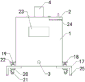
图1是本实用新型的前侧示意图;Fig. 1 is the front side schematic diagram of the utility model;
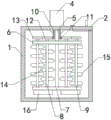
图2是本实用新型中搅拌桶的前侧剖面结构示意图;Fig. 2 is the schematic diagram of the front side section structure of the mixing tank in the utility model;
图3是本实用新型的上侧示意图;Fig. 3 is the upper schematic diagram of the utility model;
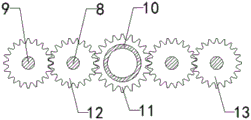
图4是本实用新型中传动齿环、内齿轮和外齿轮之间配合的上侧结构示意图;Fig. 4 is a schematic diagram of the upper structure of the cooperation between the transmission gear ring, the internal gear and the external gear in the utility model;
附图中标记:1、搅拌桶;2、加料盖;3、排料管;4、电机;5、驱动轴;6、顶板;7、底板;8、内搅拌杆;9、外搅拌杆;10、套筒;11、传动齿环;12、内齿轮;13、外齿轮;14、内搅拌叶;15、外搅拌叶;16、下搅拌叶;17、支撑架;18、调节丝杆;19、手轮;20、固定板;21、万向轮;22、锁母;23、观察窗;24、密封垫;25、防滑垫。Marks in the drawings: 1. Mixing barrel; 2. Feeding cover; 3. Discharge pipe; 4. Motor; 5. Drive shaft; 6. Top plate; 7. Bottom plate; 8. Inner stirring rod; 9. Outer stirring rod; 10. Sleeve; 11. Transmission gear ring; 12. Internal gear; 13. External gear; 14. Internal stirring blade; 15. External stirring blade; 16. Lower stirring blade; 17. Support frame; 18. Adjusting screw rod; 19. Hand wheel; 20. Fixed plate; 21. Universal wheel; 22. Lock nut; 23. Observation window; 24. Sealing pad; 25. Anti-skid pad.
具体实施方式Detailed ways
下面结合附图和实施例,对本实用新型的具体实施方式作进一步详细描述。以下实施例用于说明本实用新型,但不用来限制本实用新型的范围。Below in conjunction with accompanying drawing and embodiment, the specific embodiment of the utility model is described in further detail. The following examples are used to illustrate the utility model, but not to limit the scope of the utility model.
实施例Example
请参阅图1-4,本实用新型的一种油墨搅拌机,包括搅拌桶1,所述搅拌桶1顶端设有投料口,投料口上转动盖装有加料盖2,搅拌桶1前端下侧设有排料管3,电机4固定安装在搅拌桶1顶端,搅拌桶1内部顶端转动设有驱动轴5,并且驱动轴5与电机4输出端连接,驱动轴5上固定套设有顶板6,驱动轴5底端固定连接有底板7,顶板6和底板7之间左右对称的转动安装有两组内搅拌杆8和两组外搅拌杆9,搅拌桶1内部顶端连接有套筒10,套筒10套在驱动轴5外围,套筒10上固定套设有传动齿环11,两组内搅拌杆8顶端均固定设有内齿轮12,两组内齿轮12均与传动齿环11啮合,两组外搅拌杆9顶端均固定设有外齿轮13,两组外齿轮13分别与两组内齿轮12啮合,两组内搅拌杆8上均设有多组内搅拌叶14,两组外搅拌杆9上均设有多组外搅拌叶15,底板7底端左右对称的连接设有两组下搅拌叶16,所述支撑机构用于对搅拌桶1进行支撑;在使用时,打开加料盖2,将油墨加工所需的材料加入搅拌桶1内,然后关闭加料盖2,通过启动电机4,电机4带动驱动轴5转动,驱动轴5带动顶板6和底板7转动,使顶板6和底板7带动内搅拌杆8和外搅拌杆9围绕驱动轴5转动,与此同时,在内搅拌杆8和外搅拌杆9围绕驱动轴5转动时,内齿轮12通过与传动齿环11的啮合传动下围绕传动齿环11转动,并且内齿轮12会进行自转,内齿轮12通过自转在与外齿轮13的啮合传动下又会带动外齿轮13自转,从而使内齿轮12和外齿轮13分别带动内搅拌杆8和外搅拌杆9自转,从而使内搅拌杆8和外搅拌杆9分别带动多组内搅拌叶14和多组外搅拌叶15旋转,实现内搅拌杆8和外搅拌杆9围绕驱动轴5转动的同时进行自转,通过内搅拌叶14和外搅拌叶15的旋转对油墨溶液由内而外的进行搅拌,通过下搅拌叶16对底部进行搅拌,从而使油墨在搅拌加工时搅拌的更加均匀,使材料混合更加充分,有效提高油墨的加工质量。Please refer to Fig. 1-4, a kind of ink mixer of the present utility model, comprises mixing
请参阅图1和3,所述支撑机构包括四组支撑架17,四组支撑架17环形等距的固定安装在搅拌桶1底端,四组支撑架17上均螺装有调节丝杆18,四组调节丝杆18顶端均连接有手轮19,四组调节丝杆18底端均连接设有固定板20,四组固定板20底端均安装有万向轮21;在油墨加工时,支撑架17底端与地面接触,万向轮21处于悬空状态,这样可以使设备放置平稳,当油墨加工完后,设备需要移动时,可以通过手轮19转动调节调节丝杆18,使调节丝杆18带动固定板20向下移动,使固定板20带动万向轮21向下移动,从而可以使万向轮21与地面支撑,使支撑架17底部悬空,这样就可以推动设备进行移动。Please refer to Fig. 1 and 3, described supporting mechanism comprises four sets of support frames 17, and four sets of support frames 17 are fixedly installed in the bottom end of mixing
请参阅图1,所述四组调节丝杆18上均螺装设有锁母22;通过设置锁母22,在万向轮21支撑起搅拌桶1后,可以通过将锁母22拧紧,使调节丝杆18锁死,防止在移动过程中调节丝杆18出现转动的情况。Please refer to Fig. 1, on the four sets of adjusting
请参阅图1,所述搅拌桶1的前端设有观察窗23;通过设置观察窗23,能够便于观察搅拌桶1内部油墨的搅拌加工情况。Please refer to FIG. 1 , the front end of the
请参阅图1,所述搅拌桶1的投料口上连接设有密封垫24;通过设置密封垫24,能够使加料盖2盖装的更加严密。Please refer to FIG. 1 , the feeding port of the
请参阅图1,所述四组支撑架17的底端均连接设有防滑垫25;通过设置防滑垫25,能够增大支撑架17底部与地面的摩擦,使支撑架17放置时更加的平稳。Please refer to Fig. 1, the bottom ends of the four groups of support frames 17 are all connected with
本实用新型的一种油墨搅拌机,其在工作时,打开加料盖2,将油墨加工所需的材料加入搅拌桶1内,然后关闭加料盖2,通过启动电机4,电机4带动驱动轴5转动,驱动轴5带动顶板6和底板7转动,使顶板6和底板7带动内搅拌杆8和外搅拌杆9围绕驱动轴5转动,与此同时,在内搅拌杆8和外搅拌杆9围绕驱动轴5转动时,内齿轮12通过与传动齿环11的啮合传动下围绕传动齿环11转动,并且内齿轮12会进行自转,内齿轮12通过自转在与外齿轮13的啮合传动下又会带动外齿轮13自转,从而使内齿轮12和外齿轮13分别带动内搅拌杆8和外搅拌杆9自转,从而使内搅拌杆8和外搅拌杆9分别带动多组内搅拌叶14和多组外搅拌叶15旋转,实现内搅拌杆8和外搅拌杆9围绕驱动轴5转动的同时进行自转,通过内搅拌叶14和外搅拌叶15的旋转对油墨溶液由内而外的进行搅拌,通过下搅拌叶16对底部进行搅拌,当油墨搅拌加工好后,通过打开排料管3将油墨排出即可。An ink mixer of the utility model, when working, open the feeding
本实用新型的一种油墨搅拌机,其安装方式、连接方式或设置方式均为常见机械方式,只要能够达成其有益效果的均可进行实施;本实用新型的一种油墨搅拌机的电机为市面上采购,本行业内技术人员只需按照其附带的使用说明书进行安装和操作即可。An ink mixer of the utility model, its installation mode, connection mode or setting mode are all common mechanical methods, as long as it can achieve its beneficial effect, it can be implemented; the motor of the ink mixer of the utility model is purchased from the market , technicians in this industry only need to install and operate according to the attached instruction manual.
以上所述仅是本实用新型的优选实施方式,应当指出,对于本技术领域的普通技术人员来说,在不脱离本实用新型技术原理的前提下,还可以做出若干改进和变型,这些改进和变型也应视为本实用新型的保护范围。The above is only a preferred embodiment of the utility model, it should be pointed out that for those of ordinary skill in the art, without departing from the technical principle of the utility model, some improvements and modifications can also be made. And modification should also be regarded as the protection scope of the present utility model.
Claims (6)
Priority Applications (1)
| Application Number | Priority Date | Filing Date | Title |
|---|---|---|---|
| CN202320664905.3U CN219308523U (en) | 2023-03-30 | 2023-03-30 | Printing ink mixer |
Applications Claiming Priority (1)
| Application Number | Priority Date | Filing Date | Title |
|---|---|---|---|
| CN202320664905.3U CN219308523U (en) | 2023-03-30 | 2023-03-30 | Printing ink mixer |
Publications (1)
| Publication Number | Publication Date |
|---|---|
| CN219308523U true CN219308523U (en) | 2023-07-07 |
Family
ID=87034548
Family Applications (1)
| Application Number | Title | Priority Date | Filing Date |
|---|---|---|---|
| CN202320664905.3U Expired - Fee Related CN219308523U (en) | 2023-03-30 | 2023-03-30 | Printing ink mixer |
Country Status (1)
| Country | Link |
|---|---|
| CN (1) | CN219308523U (en) |
-
2023
- 2023-03-30 CN CN202320664905.3U patent/CN219308523U/en not_active Expired - Fee Related
Similar Documents
| Publication | Publication Date | Title |
|---|---|---|
| CN206295847U (en) | A kind of industrial material stirring mixing apparatus with scraper | |
| CN206454566U (en) | A kind of planet stirring equipment mixed suitable for high-viscosity material | |
| CN111068567A (en) | Agitating unit for building decoration coating | |
| CN106732066A (en) | The mixing device of building materials processing | |
| CN214514016U (en) | A paint mixing kettle with uniform toning for paint production | |
| CN211800540U (en) | Device for keeping automatic high-speed dispersion | |
| CN208066244U (en) | Toothpaste Manufacturing medicine extract machine | |
| CN211963821U (en) | Chicken essence production mixes machine with raw materials stirring | |
| CN207102592U (en) | A kind of epoxy resin production Bidirectional agitating apparatus | |
| CN206381919U (en) | The mixing device of building materials processing | |
| CN212215191U (en) | An asphalt mixing device | |
| CN209564979U (en) | A kind of reaction kettle stirring cleaning plant with regulatory function | |
| CN205948721U (en) | Magnetic metal powder core powder agitating unit | |
| CN208115641U (en) | A kind of stirring apparatus | |
| CN203710959U (en) | A vacuum feeding V-type mixer | |
| CN109589837A (en) | Agitating device for industrial chemicals | |
| CN210814871U (en) | Chemical raw material is with mixing stirring device | |
| CN210905800U (en) | Cosmetics allotment machine | |
| CN206613433U (en) | Realize the mixed uniformly rubber chemicals batch mixer of different material component | |
| CN219023948U (en) | Uniform mixing tank | |
| CN209989353U (en) | a mixing tank | |
| CN220496215U (en) | Mixing arrangement is used in paint production | |
| CN222079745U (en) | Plastic particle mixing device | |
| CN219482265U (en) | High efficiency material agitating unit | |
| CN221868203U (en) | A mixing and stirring device for coating production and processing |
Legal Events
| Date | Code | Title | Description |
|---|---|---|---|
| GR01 | Patent grant | ||
| GR01 | Patent grant | ||
| CP03 | Change of name, title or address |
Address after: 408000, Group 7, Da'e Village, Lidu Street Office, Fuling District, Chongqing Patentee after: CHONGQING HONGTU INK Co.,Ltd. Country or region after: China Address before: 408102 group 7, DAE village, Lidu sub district office, Fuling District, Chongqing Patentee before: Chongqing Hongtu New Materials Technology Co.,Ltd. Country or region before: China |
|
| CP03 | Change of name, title or address | ||
| CF01 | Termination of patent right due to non-payment of annual fee |
Granted publication date: 20230707 |
|
| CF01 | Termination of patent right due to non-payment of annual fee |