CN219298752U - Building aluminum alloy template convenient to drawing of patterns - Google Patents
Building aluminum alloy template convenient to drawing of patterns Download PDFInfo
- Publication number
- CN219298752U CN219298752U CN202320091347.6U CN202320091347U CN219298752U CN 219298752 U CN219298752 U CN 219298752U CN 202320091347 U CN202320091347 U CN 202320091347U CN 219298752 U CN219298752 U CN 219298752U
- Authority
- CN
- China
- Prior art keywords
- aluminum alloy
- alloy formwork
- alloy template
- main body
- template main
- Prior art date
- Legal status (The legal status is an assumption and is not a legal conclusion. Google has not performed a legal analysis and makes no representation as to the accuracy of the status listed.)
- Expired - Fee Related
Links
Images
Classifications
-
- Y—GENERAL TAGGING OF NEW TECHNOLOGICAL DEVELOPMENTS; GENERAL TAGGING OF CROSS-SECTIONAL TECHNOLOGIES SPANNING OVER SEVERAL SECTIONS OF THE IPC; TECHNICAL SUBJECTS COVERED BY FORMER USPC CROSS-REFERENCE ART COLLECTIONS [XRACs] AND DIGESTS
- Y02—TECHNOLOGIES OR APPLICATIONS FOR MITIGATION OR ADAPTATION AGAINST CLIMATE CHANGE
- Y02E—REDUCTION OF GREENHOUSE GAS [GHG] EMISSIONS, RELATED TO ENERGY GENERATION, TRANSMISSION OR DISTRIBUTION
- Y02E10/00—Energy generation through renewable energy sources
- Y02E10/20—Hydro energy
Landscapes
- Conveying And Assembling Of Building Elements In Situ (AREA)
- Tents Or Canopies (AREA)
Abstract
本实用新型公开了一种便于脱模的建筑铝合金模板,包括铝合金模板主体,横向相邻两个所述铝合金模板主体的中间设置有安装机构,且纵向相邻两个所述铝合金模板主体的中间设置有拆卸机构。该便于脱模的建筑铝合金模板,在实际组装的过程中,横向相邻的两个铝合金模板主体能够通过一个铝合金模板主体上的插接块插入另一铝合金模板主体上的插接孔内,此时滑动板能够在若干个复位弹簧的作用下恢复原位,使定位柱插入插接孔内并与插接块上的定位孔插接,实现对横向相邻两个铝合金模板主体的快速安装,且在脱模的过程中,仅仅需要向外拉动拉环,并向两侧拉动铝合金模板主体,即能够实现快速拆卸,便于进行脱模工作,有效的缩短了脱模的时间。

The utility model discloses a building aluminum alloy formwork which is convenient for demoulding, which comprises an aluminum alloy formwork main body, an installation mechanism is arranged in the middle of two adjacent aluminum alloy formwork main bodies in the transverse direction, and two aluminum alloy formwork bodies are adjacent in the longitudinal direction. A disassembly mechanism is provided in the middle of the formwork body. In the actual assembly process of the building aluminum alloy formwork that is easy to demould, two laterally adjacent aluminum alloy formwork bodies can be inserted into the socket on the other aluminum alloy formwork body through the plug-in block on one aluminum alloy formwork body. At this time, the sliding plate can return to its original position under the action of several return springs, so that the positioning column can be inserted into the insertion hole and connected with the positioning hole on the insertion block, so as to realize the alignment of two aluminum alloy formworks adjacent to each other in the horizontal direction. The main body is quickly installed, and in the process of demoulding, it is only necessary to pull the pull ring outward and pull the main body of the aluminum alloy formwork to both sides, which can realize quick disassembly, facilitate demoulding work, and effectively shorten the demoulding time. time.
Description
技术领域technical field
本实用新型涉及建筑工程技术领域,具体为一种便于脱模的建筑铝合金模板。The utility model relates to the technical field of construction engineering, in particular to a construction aluminum alloy formwork which is convenient for demoulding.
背景技术Background technique
铝合金模板是铝合金制作的建筑模板,是指按模数制作设计、经专用设备挤压后制作而成、由铝面板、支架和连接件三部分系统所组成的具有完整的配套使用的通用配件。Aluminum alloy formwork is a building formwork made of aluminum alloy. It refers to the design according to the modulus, and it is made by extruding special equipment. It is composed of three parts: aluminum panels, brackets and connectors. Accessories.
目前现有的建筑用铝合金模板在安装时,相邻的两个模板之间大多是通过若干个螺栓进行连接,缺乏快速连接机构,导致这种连接方式在脱模的过程中,需要逐一拧动若干个螺栓,非常不便,而且脱模花费的时间较长。At present, when the existing aluminum alloy formwork for construction is installed, two adjacent formworks are mostly connected by several bolts, lacking a quick connection mechanism, which leads to the need to twist one by one during the demoulding process of this connection method. It is very inconvenient to move several bolts, and it takes a long time to demould.
为此,我们提出一种便于脱模的建筑铝合金模板。Therefore, we propose a building aluminum alloy formwork that is easy to demould.
实用新型内容Utility model content
本实用新型的目的在于提供一种便于脱模的建筑铝合金模板,以解决上述背景技术中提出的问题。The purpose of this utility model is to provide a building aluminum alloy formwork that is easy to demould, so as to solve the problems raised in the above-mentioned background technology.
为实现上述目的,本实用新型提供如下技术方案:一种便于脱模的建筑铝合金模板,包括铝合金模板主体,横向相邻两个所述铝合金模板主体的中间设置有安装机构,且纵向相邻两个所述铝合金模板主体的中间设置有拆卸机构;In order to achieve the above purpose, the utility model provides the following technical solutions: a building aluminum alloy formwork that is easy to demould, including an aluminum alloy formwork main body, an installation mechanism is arranged in the middle of two adjacent aluminum alloy formwork main bodies in the horizontal direction, and A disassembly mechanism is provided in the middle of two adjacent aluminum alloy formwork bodies;
所述安装机构包括固设在一个铝合金模板主体表面的插接块以及开设在另一个铝合金模板主体表面的插接孔,所述安装机构还包括固设在开设有插接孔的铝合金模板主体表面的安装框,安装框的内壁滑动连接有滑动板,滑动板的背面固设有与插接孔相对应的定位柱,铝合金模板主体和插接块的表面均开设有与定位柱相适配的定位孔,且插接孔的内壁开设有与定位柱相适配的定位槽;The installation mechanism includes a plug-in block fixed on the surface of one aluminum alloy formwork body and an insertion hole opened on the surface of the other aluminum alloy formwork body. The installation frame on the surface of the main body of the formwork, the inner wall of the installation frame is slidably connected with a sliding plate, the back of the sliding plate is fixed with a positioning column corresponding to the insertion hole, and the surface of the main body of the aluminum alloy formwork and the insertion block are provided with a positioning column Compatible positioning holes, and the inner wall of the insertion hole is provided with a positioning groove that is compatible with the positioning column;
所述安装框的表面开设有滑动孔,且滑动孔的内壁滑动连接有滑动柱,滑动柱的一端固设有拉环,滑动柱的另一端与滑动板的表面固定连接。The surface of the installation frame is provided with a sliding hole, and the inner wall of the sliding hole is slidably connected with a sliding column, one end of the sliding column is fixed with a pull ring, and the other end of the sliding column is fixedly connected with the surface of the sliding plate.
优选的,所述滑动板的表面固设有若干个复位弹簧,且若干个复位弹簧远离滑动板的一端均与安装框的内壁固定连接,便于滑动板进行复位。Preferably, several return springs are fixed on the surface of the slide plate, and the ends of the several return springs away from the slide plate are all fixedly connected to the inner wall of the installation frame, so as to facilitate the reset of the slide plate.
优选的,所述拆卸机构包括分别固设在两个铝合金模板主体中心表面的L型安装杆,便于对纵向的两个铝合金模板主体进行分离脱模。Preferably, the dismounting mechanism includes L-shaped installation rods respectively fixed on the central surfaces of the two aluminum alloy formwork bodies, so as to facilitate the separation and demoulding of the two longitudinal aluminum alloy formwork bodies.
优选的,一个所述L型安装杆的端部转动设置有丝杠,且另一个L型安装杆的端部开设有与丝杠表面螺纹连接的柱形螺纹槽。Preferably, the end of one L-shaped installation rod is rotatably provided with a lead screw, and the end of the other L-shaped installation rod is provided with a cylindrical thread groove threadedly connected with the surface of the lead screw.
优选的,所述丝杠的表面套设有固定有用于转动丝杠的六角形转动套,便于操作人员能够通过手部或者外部扳手转动六角转动套。Preferably, the surface of the lead screw is covered with a hexagonal rotating sleeve fixed for rotating the screw, so that the operator can rotate the hexagonal rotating sleeve by hand or an external wrench.
有益效果Beneficial effect
本实用新型提供了一种便于脱模的建筑铝合金模板,具备以下有益效果:The utility model provides a building aluminum alloy formwork which is convenient for demoulding, and has the following beneficial effects:
1.该便于脱模的建筑铝合金模板,在脱模的过程中,仅仅需要向外拉动拉环,并向两侧拉动铝合金模板主体,即能够实现快速拆卸,便于进行脱模工作,有效的缩短了脱模的时间。1. The architectural aluminum alloy formwork that is easy to demould, in the process of demoulding, only needs to pull the pull ring outward, and pull the main body of the aluminum alloy formwork to both sides, which can realize quick disassembly, facilitate demoulding work, and effectively shorten the time for demoulding.
2.该便于脱模的建筑铝合金模板,在对两个纵向的铝合金模板主体进行脱模时,能够通过转动六角形转动套带动丝杠转动,丝杠的转动在柱形螺纹槽的作用下带动L型安装杆向外移动,进而实现两个纵向铝合金模板主体与混凝土的快速脱离,进一步实现快速脱模的目的。2. The building aluminum alloy formwork that is easy to demould can drive the lead screw to rotate by turning the hexagonal rotating sleeve when the two longitudinal aluminum alloy formwork main bodies are demoulded, and the rotation of the lead screw is driven by the action of the cylindrical thread groove The L-shaped installation rod moves outwards, thereby realizing the rapid separation of the two longitudinal aluminum alloy formwork bodies from the concrete, and further realizing the purpose of rapid demoulding.
附图说明Description of drawings
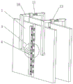
图1为本实用新型立体结构示意图;Fig. 1 is a schematic diagram of the three-dimensional structure of the utility model;
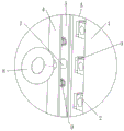
图2为本实用新型图1中A处放大结构示意图;Fig. 2 is the schematic diagram of enlarged structure at A place in Fig. 1 of the utility model;
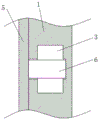
图3为本实用新型插接孔侧剖结构示意图;Fig. 3 is a schematic diagram of the side section structure of the socket hole of the utility model;
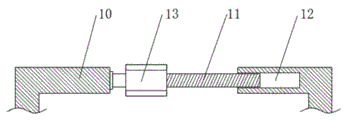
图4为本实用新型L型安装杆侧剖结构示意图。Fig. 4 is a schematic diagram of a side section structure of an L-shaped mounting rod of the present invention.
图中:1铝合金模板主体、2插接块、3插接孔、4安装框、5滑动板、6定位柱、7滑动柱、8拉环、9复位弹簧、10 L型安装杆、11丝杠、12柱形螺纹槽、13六角形转动套。In the figure: 1 aluminum alloy formwork main body, 2 socket block, 3 socket hole, 4 installation frame, 5 sliding plate, 6 positioning column, 7 sliding column, 8 pull ring, 9 return spring, 10 L-shaped installation rod, 11 Lead screw, 12 cylindrical thread grooves, 13 hexagonal rotating sleeves.
具体实施方式Detailed ways
下面将结合本实用新型实施例中的附图,对本实用新型实施例中的技术方案进行清楚、完整地描述,显然,所描述的实施例仅仅是本实用新型一部分实施例,而不是全部的实施例。基于本实用新型中的实施例,本领域普通技术人员在没有做出创造性劳动前提下所获得的所有其他实施例,都属于本实用新型保护的范围。The technical solutions in the embodiments of the present invention will be clearly and completely described below in conjunction with the accompanying drawings in the embodiments of the present invention. Obviously, the described embodiments are only part of the embodiments of the present invention, not all of them. example. Based on the embodiments of the present utility model, all other embodiments obtained by persons of ordinary skill in the art without making creative efforts belong to the scope of protection of the present utility model.
请参阅图1-4,本实用新型提供一种技术方案:一种便于脱模的建筑铝合金模板,包括铝合金模板主体1,横向相邻两个铝合金模板主体1的中间设置有安装机构,且纵向相邻两个铝合金模板主体1的中间设置有拆卸机构;Please refer to Figures 1-4, the utility model provides a technical solution: a building aluminum alloy formwork that is easy to demould, including an aluminum alloy formwork
安装机构包括固设在一个铝合金模板主体1表面的插接块2以及开设在另一个铝合金模板主体1表面的插接孔3,安装机构还包括固设在开设有插接孔3的铝合金模板主体1表面的安装框4,安装框4的内壁滑动连接有滑动板5,滑动板5的表面固设有若干个复位弹簧9,且若干个复位弹簧9远离滑动板5的一端均与安装框4的内壁固定连接。The installation mechanism includes a plug-in
滑动板5的背面固设有与插接孔3相对应的定位柱6,铝合金模板主体1和插接块2的表面均开设有与定位柱6相适配的定位孔,且插接孔3的内壁开设有与定位柱6相适配的定位槽;The back side of the
安装框4的表面开设有滑动孔,且滑动孔的内壁滑动连接有滑动柱7,滑动柱7的一端固设有拉环8,滑动柱7的另一端与滑动板5的表面固定连接。The surface of the mounting frame 4 is provided with a sliding hole, and the inner wall of the sliding hole is slidably connected with a
该便于脱模的建筑铝合金模板,在实际组装的过程中,横向相邻的两个铝合金模板主体1能够通过一个铝合金模板主体1上的插接块2插入另一铝合金模板主体1上的插接孔3内,且在插入之前先向外拉动拉环8,使定位柱6远离插接孔3,插接完成后,松开拉环8,此时滑动板5能够在若干个复位弹簧9的作用下恢复原位,使定位柱6插入插接孔3内并与插接块2上的定位孔插接,实现对横向相邻两个铝合金模板主体1的快速安装,且在脱模的过程中,仅仅需要向外拉动拉环8,并向两侧拉动铝合金模板主体1,即能够实现快速拆卸,便于进行脱模工作,有效的缩短了脱模的时间。In the actual assembly process of the building aluminum alloy formwork that is easy to demould, two laterally adjacent aluminum alloy formwork
拆卸机构包括分别固设在两个铝合金模板主体1中心表面的L型安装杆10。The dismantling mechanism includes L-
一个L型安装杆10的端部转动设置有丝杠11,且另一个L型安装杆10的端部开设有与丝杠11表面螺纹连接的柱形螺纹槽12。The end of one L-
丝杠11的表面套设有固定有用于转动丝杠11的六角形转动套13。The surface of the
该便于脱模的建筑铝合金模板,在对两个纵向的铝合金模板主体1进行脱模时,能够通过转动六角形转动套13带动丝杠11转动,丝杠11的转动在柱形螺纹槽12的作用下带动L型安装杆10向外移动,进而实现两个纵向铝合金模板主体1与混凝土的快速脱离,进一步实现快速脱模的目的。The building aluminum alloy formwork that is easy to demould can drive the
尽管已经示出和描述了本实用新型的实施例,对于本领域的普通技术人员而言,可以理解在不脱离本实用新型的原理和精神的情况下可以对这些实施例进行多种变化、修改、替换和变型,本实用新型的范围由所附权利要求及其等同物限定。Although the embodiments of the present invention have been shown and described, those skilled in the art can understand that various changes and modifications can be made to these embodiments without departing from the principle and spirit of the present invention , replacements and modifications, the scope of the present utility model is defined by the appended claims and their equivalents.
Claims (5)
Priority Applications (1)
| Application Number | Priority Date | Filing Date | Title |
|---|---|---|---|
| CN202320091347.6U CN219298752U (en) | 2023-01-31 | 2023-01-31 | Building aluminum alloy template convenient to drawing of patterns |
Applications Claiming Priority (1)
| Application Number | Priority Date | Filing Date | Title |
|---|---|---|---|
| CN202320091347.6U CN219298752U (en) | 2023-01-31 | 2023-01-31 | Building aluminum alloy template convenient to drawing of patterns |
Publications (1)
| Publication Number | Publication Date |
|---|---|
| CN219298752U true CN219298752U (en) | 2023-07-04 |
Family
ID=86986700
Family Applications (1)
| Application Number | Title | Priority Date | Filing Date |
|---|---|---|---|
| CN202320091347.6U Expired - Fee Related CN219298752U (en) | 2023-01-31 | 2023-01-31 | Building aluminum alloy template convenient to drawing of patterns |
Country Status (1)
| Country | Link |
|---|---|
| CN (1) | CN219298752U (en) |
-
2023
- 2023-01-31 CN CN202320091347.6U patent/CN219298752U/en not_active Expired - Fee Related
Similar Documents
| Publication | Publication Date | Title |
|---|---|---|
| CN213174803U (en) | A kind of concrete building formwork for civil engineering | |
| CN117344967A (en) | A quick assembly and disassembly device for a modular mold with an inner mold in the opening and its use method | |
| CN114438898A (en) | Butt joint device for mounting distribution beam for steel beam pushing construction and use method thereof | |
| CN220267223U (en) | Building construction template easy dismounting device | |
| CN218226410U (en) | Industrial equipment basic template device | |
| CN214081999U (en) | Production mould of component for energy-saving panel of assembled building | |
| CN212078687U (en) | A building template for building construction | |
| CN221872442U (en) | Assembled building mold | |
| CN209887525U (en) | A multifunctional universal wrench with adjustable angle | |
| CN223974878U (en) | Aluminum alloy template for external corners of wall | |
| CN109057330B (en) | Device for realizing early dismantling and quick dismantling of building template | |
| CN218117201U (en) | Combined assembled waterproof building template | |
| CN219862243U (en) | A road shoulder concrete construction formwork | |
| CN221112301U (en) | A ceramic demoulding tool for pump body lining | |
| CN217126750U (en) | Tower machine standard festival convenient to dismouting transportation | |
| CN221390875U (en) | A dismounting device for construction steel mould board | |
| CN218363335U (en) | A multi-functional tooling quick change device | |
| CN221646391U (en) | A concrete pouring reserved hole formwork device | |
| CN219411812U (en) | An easy-to-install building formwork | |
| CN218933422U (en) | Connecting piece of steel structure building | |
| CN216948791U (en) | A detachable pre-embedded connecting wall based on steel sleeve | |
| CN219569539U (en) | Right-angle type aluminum alloy template for building | |
| CN219451040U (en) | An assembly connector for an assembly structure | |
| CN217144416U (en) | Diamond drilling machine | |
| CN218815213U (en) | Building bay window mould |
Legal Events
| Date | Code | Title | Description |
|---|---|---|---|
| GR01 | Patent grant | ||
| GR01 | Patent grant | ||
| CF01 | Termination of patent right due to non-payment of annual fee | ||
| CF01 | Termination of patent right due to non-payment of annual fee |
Granted publication date: 20230704 |