CN219298409U - Dredge pump with prevent stifled structure - Google Patents
Dredge pump with prevent stifled structure Download PDFInfo
- Publication number
- CN219298409U CN219298409U CN202223428179.XU CN202223428179U CN219298409U CN 219298409 U CN219298409 U CN 219298409U CN 202223428179 U CN202223428179 U CN 202223428179U CN 219298409 U CN219298409 U CN 219298409U
- Authority
- CN
- China
- Prior art keywords
- sewage
- fixedly connected
- filter
- sewage pump
- groove
- Prior art date
- Legal status (The legal status is an assumption and is not a legal conclusion. Google has not performed a legal analysis and makes no representation as to the accuracy of the status listed.)
- Expired - Fee Related
Links
Images

Classifications
-
- Y—GENERAL TAGGING OF NEW TECHNOLOGICAL DEVELOPMENTS; GENERAL TAGGING OF CROSS-SECTIONAL TECHNOLOGIES SPANNING OVER SEVERAL SECTIONS OF THE IPC; TECHNICAL SUBJECTS COVERED BY FORMER USPC CROSS-REFERENCE ART COLLECTIONS [XRACs] AND DIGESTS
- Y02—TECHNOLOGIES OR APPLICATIONS FOR MITIGATION OR ADAPTATION AGAINST CLIMATE CHANGE
- Y02A—TECHNOLOGIES FOR ADAPTATION TO CLIMATE CHANGE
- Y02A20/00—Water conservation; Efficient water supply; Efficient water use
- Y02A20/20—Controlling water pollution; Waste water treatment
Landscapes
- Separation Of Solids By Using Liquids Or Pneumatic Power (AREA)
Abstract
本实用新型公开了一种具有防堵结构的排污泵,具体涉及排污技术领域,包括排污泵主体,所述排污泵主体上设置有进水嘴和排水嘴,所述进水嘴输入端固定连接有过滤机构,所述过滤机构包括过滤管。本实用新型的排污泵主体在将污水抽入进水嘴前,污水会穿过过滤管,在污水穿过过滤管的过程中,污水中的大颗粒泥沙等杂质被拦截收集于集污壳内,污水再依次穿设孔和活性炭滤网,活性炭滤网将污水中的小颗粒杂质吸附去除,本设计解决了现有技术下的不足,能够避免污水中的杂质进入排污泵主体内部造成排污泵主体内部的损伤或堵塞,对排污泵主体起到了良好的保护作用,除此之外,此设计操作起来简单方便,极大的方便了使用者对集污壳和活性炭滤网的清理或更换。

The utility model discloses a sewage pump with an anti-blocking structure, specifically relates to the technical field of sewage, comprising a main body of the sewage pump, the main body of the sewage pump is provided with a water inlet nozzle and a water discharge nozzle, and the input end of the water inlet nozzle is fixedly connected There is a filter mechanism, which includes a filter tube. Before the main body of the sewage pump of the utility model pumps the sewage into the water inlet, the sewage will pass through the filter pipe. During the process of the sewage passing through the filter pipe, impurities such as large particles of silt in the sewage are intercepted and collected in the sewage collection shell. Inside, the sewage passes through holes and activated carbon filter in turn, and the activated carbon filter absorbs and removes small particles of impurities in the sewage. This design solves the shortcomings of the existing technology and can prevent impurities in the sewage from entering the main body of the sewage pump to cause sewage discharge. The damage or blockage inside the pump main body plays a good role in protecting the main body of the sewage pump. In addition, this design is simple and convenient to operate, which greatly facilitates the user to clean or replace the sewage collection shell and activated carbon filter. .
Description
技术领域technical field
本实用新型涉及排污技术领域,具体为一种具有防堵结构的排污泵。The utility model relates to the technical field of sewage discharge, in particular to a sewage pump with an anti-blocking structure.
背景技术Background technique
排污泵是一种泵与电机连体的泵类产品,与一般卧式泵或立式污水泵相比,排污泵结构紧凑、占地面积小且安装维修方便。Sewage pump is a pump product in which the pump and motor are integrated. Compared with ordinary horizontal pumps or vertical sewage pumps, the sewage pump has a compact structure, a small footprint, and is easy to install and maintain.
现有技术中存在以下问题:There are following problems in the prior art:
现有技术下,排污泵工作时将污水由进水嘴抽入,将污水由排水嘴排出,但污水中含有各种杂质,这些杂质会伴随污水由进水嘴进入排污泵内部,从而对排污泵内部造成损伤或堵塞,为此,我们提出一种具有防堵结构的排污泵用于解决上述问题。Under the existing technology, when the sewage pump is working, the sewage is sucked in from the water inlet and discharged from the discharge nozzle, but the sewage contains various impurities, and these impurities will enter the interior of the sewage pump through the water inlet along with the sewage, thereby affecting the discharge of sewage. The inside of the pump is damaged or blocked. Therefore, we propose a sewage pump with an anti-blocking structure to solve the above problems.
实用新型内容Utility model content
本实用新型旨在解决现有技术或相关技术中存在的技术问题之一。The utility model aims to solve one of the technical problems existing in the prior art or the related art.
为此,本实用新型所采用的技术方案为:For this reason, the technical scheme that the utility model adopts is:
一种具有防堵结构的排污泵,包括排污泵主体,所述排污泵主体上设置有进水嘴和排水嘴,所述进水嘴输入端固定连接有过滤机构。A sewage pump with an anti-blocking structure, comprising a main body of the sewage pump, the main body of the sewage pump is provided with a water inlet nozzle and a water discharge nozzle, and the input end of the water inlet nozzle is fixedly connected with a filter mechanism.
所述过滤机构包括过滤管,所述过滤管内部设置有除杂组件和集污壳,所述过滤管顶部设置有固定组件,所述集污壳用于去除污水中的大颗粒泥沙等杂质,所述除杂组件用于去除污水中的小颗粒杂质,所述固定组件用于将除杂组件固定于过滤管内。The filter mechanism includes a filter tube, the inside of the filter tube is provided with an impurity removal assembly and a dirt collection shell, the top of the filter tube is provided with a fixed assembly, and the dirt collection shell is used to remove impurities such as large particles of silt in the sewage , the impurity removal component is used to remove small particle impurities in the sewage, and the fixing component is used to fix the impurity removal component in the filter pipe.
优选地,所述过滤管一端固定连接有第二法兰,所述过滤管另一端固定连接有第三法兰,所述进水嘴输入端固定连接有第一法兰,所述第一法兰与第二法兰之间通过螺钉固定连接。Preferably, one end of the filter tube is fixedly connected with a second flange, the other end of the filter tube is fixedly connected with a third flange, the input end of the water inlet is fixedly connected with a first flange, and the first flange The flange and the second flange are fixedly connected by screws.
优选地,所述过滤管一端开设有呈条形结构的导向槽,所述导向槽均匀设置有四个,所述过滤管另一端开设有定位槽,所述定位槽槽底开设有螺纹槽,所述螺纹槽均匀设置有四个。Preferably, one end of the filter tube is provided with guide grooves in a bar-shaped structure, and four guide grooves are evenly arranged, and the other end of the filter tube is provided with a positioning groove, and the bottom of the positioning groove is provided with a threaded groove, There are four thread grooves evenly arranged.
优选地,所述除杂组件包括固定环,所述固定环呈圆形环状结构,所述固定环中心处设置有中心柱,所述中心柱与固定环之间通过连接杆固定连接,所述连接杆均匀设置有四个,相邻的两个所述连接杆之间安装有活性炭滤网。Preferably, the impurity removal assembly includes a fixed ring, the fixed ring has a circular ring structure, a central column is arranged at the center of the fixed ring, and the central column and the fixed ring are fixedly connected by a connecting rod, so that Four connecting rods are evenly arranged, and activated carbon filter screens are installed between two adjacent connecting rods.
优选地,所述固定环外圆面固定连接有导向块,所述导向块均匀设置有四个,所述导向块表面与导向槽槽壁滑动连接,位于顶部的所述导向块顶部开设有对接槽,所述中心柱一侧固定连接有抽拉把手。Preferably, guide blocks are fixedly connected to the outer surface of the fixed ring, and four guide blocks are evenly arranged, and the surface of the guide blocks is slidably connected to the wall of the guide groove, and the top of the guide block at the top is provided with a butt joint a slot, and a pull handle is fixedly connected to one side of the center column.
优选地,所述集污壳内腔底部密集开设有穿设孔,所述集污壳一侧固定连接有定位环,所述定位环位于定位槽内,所述定位环上设置有螺栓,所述螺栓对应螺纹槽设置有四个,所述螺栓一端设置有外螺纹,螺纹槽内设置有内螺纹,所述外螺纹与内螺纹相匹配。Preferably, the bottom of the inner cavity of the dirt collecting shell is densely provided with piercing holes, one side of the dirt collecting shell is fixedly connected with a positioning ring, the positioning ring is located in the positioning groove, and the positioning ring is provided with bolts, so that The bolts are provided with four corresponding thread grooves, one end of the bolt is provided with an external thread, and the thread groove is provided with an internal thread, and the external thread matches the internal thread.
优选地,所述固定组件包括运动条,所述运动条底部设置有延伸块,所述延伸块对称设置有两个,所述延伸块底部与过滤管顶部固定连接,所述延伸块顶部固定连接有滑动杆,所述滑动杆顶端固定连接有限位块,所述运动条两端与滑动杆表面滑动连接。Preferably, the fixing assembly includes a movement bar, the bottom of the movement bar is provided with an extension block, and two extension blocks are arranged symmetrically, the bottom of the extension block is fixedly connected to the top of the filter tube, and the top of the extension block is fixedly connected There is a sliding rod, the top of the sliding rod is fixedly connected to the limit block, and the two ends of the moving bar are slidingly connected to the surface of the sliding rod.
优选地,所述运动条底部中心处固定连接有对接柱,所述对接柱底端穿过过滤管顶部并竖直向下延伸至对接槽内,所述滑动杆表面套设有第一弹簧和第二弹簧,所述第一弹簧一端与限位块底部固定连接,所述第一弹簧另一端与运动条顶部固定连接,所述第二弹簧一端与运动条底部固定连接,所述第二弹簧另一端与延伸块顶部固定连接,所述运动条上的固定连接有拨动块。Preferably, a docking column is fixedly connected to the center of the bottom of the moving bar, the bottom end of the docking column passes through the top of the filter tube and extends vertically downwards into the docking groove, and the surface of the sliding rod is sleeved with a first spring and The second spring, one end of the first spring is fixedly connected to the bottom of the limit block, the other end of the first spring is fixedly connected to the top of the moving bar, one end of the second spring is fixedly connected to the bottom of the moving bar, and the second spring The other end is fixedly connected to the top of the extension block, and a toggle block is fixedly connected to the moving bar.
通过采用上述技术方案,本实用新型所取得的有益效果为:By adopting the above-mentioned technical scheme, the beneficial effects obtained by the utility model are:
本实用新型的排污泵主体在将污水抽入进水嘴前,污水会穿过过滤管,在污水穿过过滤管的过程中,污水中的大颗粒泥沙等杂质被拦截收集于集污壳内,污水再依次穿设孔和活性炭滤网,活性炭滤网将污水中的小颗粒杂质吸附去除,本设计解决了现有技术下的不足,能够避免污水中的杂质进入排污泵主体内部造成排污泵主体内部的损伤或堵塞,对排污泵主体起到了良好的保护作用,并且集污壳的设计避免了大颗粒杂质将活性炭滤网堵塞划伤,延长了活性炭滤网的使用寿命提升了过滤效果,除此之外,当集污壳和活性炭滤网需要清理或更换时,使用者拆下螺钉使得第一法兰与第二法兰之间分离,再竖直向上拉动拨动块,拨动块驱动对接柱从对接槽内脱离,使用者即可将固定环从过滤管内向外抽出对活性炭滤网进行清理或更换,使用者拧下螺栓,即可将集污壳从过滤管内抽出进行清理或更换,此设计操作起来简单方便,极大的方便了使用者对集污壳和活性炭滤网的清理或更换。Before the main body of the sewage pump of the utility model pumps the sewage into the water inlet, the sewage will pass through the filter pipe. During the process of the sewage passing through the filter pipe, impurities such as large particles of silt in the sewage are intercepted and collected in the sewage collection shell. Inside, the sewage passes through holes and activated carbon filter in turn, and the activated carbon filter absorbs and removes small particles of impurities in the sewage. This design solves the shortcomings of the existing technology and can prevent impurities in the sewage from entering the main body of the sewage pump to cause sewage discharge. The damage or blockage inside the pump body plays a good role in protecting the main body of the sewage pump, and the design of the sewage collection shell prevents large particles of impurities from blocking and scratching the activated carbon filter, prolonging the service life of the activated carbon filter and improving the filtering effect , in addition, when the dirt collection shell and the activated carbon filter screen need to be cleaned or replaced, the user removes the screws to separate the first flange from the second flange, and then pulls the toggle block vertically upwards to toggle The block drives the docking column to disengage from the docking groove, the user can pull out the fixing ring from the filter tube to clean or replace the activated carbon filter, and the user can unscrew the bolt to pull out the dirt collection shell from the filter tube for cleaning Or replacement, this design is simple and convenient to operate, which greatly facilitates the user to clean or replace the dirt collection shell and activated carbon filter.
附图说明Description of drawings
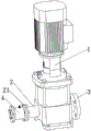
图1为本实用新型的整体结构示意图。Figure 1 is a schematic diagram of the overall structure of the utility model.
图2为本实用新型的过滤机构结构示意图。Fig. 2 is a structural schematic diagram of the filter mechanism of the present invention.
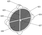
图3为本实用新型的除杂组件结构示意图。Fig. 3 is a structural schematic diagram of the impurity removal component of the present invention.
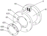
图4为本实用新型的过滤机构爆炸图。Fig. 4 is an exploded view of the filter mechanism of the present invention.
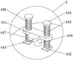
图5为本实用新型的A处结构放大图。Figure 5 is an enlarged view of the structure at A of the present invention.
图中:1、排污泵主体;2、进水嘴;21、第一法兰;3、排水嘴;4、过滤机构;41、过滤管;411、第二法兰;412、第三法兰;413、导向槽;414、定位槽;415、螺纹槽;42、除杂组件;421、固定环;422、中心柱;423、连接杆;424、导向块;425、对接槽;426、活性炭滤网;427、抽拉把手;43、集污壳;431、穿设孔;432、螺栓;433、定位环;44、固定组件;441、运动条;442、延伸块;443、滑动杆;444、限位块;445、拨动块;446、第一弹簧;447、第二弹簧;448、对接柱。In the figure: 1. Main body of sewage pump; 2. Water inlet nozzle; 21. First flange; 3. Drainage nozzle; 4. Filter mechanism; 41. Filter pipe; 411. Second flange; 412.
具体实施方式Detailed ways
下面将结合本实用新型实施例中的附图,对本实用新型实施例中的技术方案进行清楚、完整地描述,显然,所描述的实施例仅仅是本实用新型一部分实施例,而不是全部的实施例。基于本实用新型中的实施例,本领域普通技术人员在没有做出创造性劳动前提下所获得的所有其他实施例,都属于本实用新型保护的范围。The technical solutions in the embodiments of the present invention will be clearly and completely described below in conjunction with the accompanying drawings in the embodiments of the present invention. Obviously, the described embodiments are only part of the embodiments of the present invention, not all of them. example. Based on the embodiments of the present utility model, all other embodiments obtained by persons of ordinary skill in the art without making creative efforts belong to the scope of protection of the present utility model.
实施例:如图1-5所示,本实用新型提供了一种具有防堵结构的排污泵,包括排污泵主体1,排污泵主体1上设置有进水嘴2和排水嘴3,进水嘴2输入端固定连接有过滤机构4。Embodiment: As shown in Figures 1-5, the utility model provides a sewage pump with an anti-blocking structure, including a sewage pump
进一步的,过滤机构4包括过滤管41,过滤管41内部设置有除杂组件42和集污壳43,过滤管41顶部设置有固定组件44,集污壳43用于去除污水中的大颗粒泥沙等杂质,除杂组件42用于去除污水中的小颗粒杂质,固定组件44用于将除杂组件42固定于过滤管41内,过滤管41一端固定连接有第二法兰411,过滤管41另一端固定连接有第三法兰412,第三法兰412用于将过滤管41与外接管道连接,进水嘴2输入端固定连接有第一法兰21,第一法兰21与第二法兰411之间通过螺钉固定连接,过滤管41一端开设有呈条形结构的导向槽413,导向槽413均匀设置有四个,过滤管41另一端开设有定位槽414,定位槽414槽底开设有螺纹槽415,螺纹槽415均匀设置有四个。Further, the
进一步的,除杂组件42包括固定环421,固定环421呈圆形环状结构,固定环421中心处设置有中心柱422,中心柱422与固定环421之间通过连接杆423固定连接,连接杆423均匀设置有四个,相邻的两个连接杆423之间安装有活性炭滤网426,活性炭滤网426能够将污水中的小颗粒杂质吸附去除,固定环421外圆面固定连接有导向块424,导向块424均匀设置有四个,导向块424表面与导向槽413槽壁滑动连接,导向块424与导向槽413相互配合方便了使用者将固定环421插入过滤管41内部,位于顶部的导向块424顶部开设有对接槽425,中心柱422一侧固定连接有抽拉把手427,抽拉把手427方便了使用者将固定环421从过滤管41内抽出。Further, the
进一步的,集污壳43内腔底部密集开设有穿设孔431,集污壳43能够将污水中的大颗粒泥沙等杂质拦截,穿设孔431用于穿过污水,集污壳43一侧固定连接有定位环433,定位环433位于定位槽414内,定位环433上设置有螺栓432,螺栓432对应螺纹槽415设置有四个,螺栓432一端设置有外螺纹,螺纹槽415内设置有内螺纹,外螺纹与内螺纹相匹配,使用者拧下螺栓432,即可将集污壳43从过滤管41内抽出进行清理或更换,操作起来简单方便。Further, the bottom of the inner cavity of the
进一步的,固定组件44包括运动条441,运动条441底部设置有延伸块442,延伸块442对称设置有两个,延伸块442底部与过滤管41顶部固定连接,延伸块442顶部固定连接有滑动杆443,滑动杆443顶端固定连接有限位块444,运动条441两端与滑动杆443表面滑动连接,且运动条441与滑动杆443之间构成了沿滑动杆443轴线方向的滑动导向配合,运动条441底部中心处固定连接有对接柱448,对接柱448底端穿过过滤管41顶部并竖直向下延伸至对接槽425内,滑动杆443表面套设有第一弹簧446和第二弹簧447,第一弹簧446一端与限位块444底部固定连接,第一弹簧446另一端与运动条441顶部固定连接,第二弹簧447一端与运动条441底部固定连接,第二弹簧447另一端与延伸块442顶部固定连接,运动条441上的固定连接有拨动块445,第一弹簧446和第二弹簧447的弹力能够驱使对接柱448进入对接槽425内,对接柱448与对接槽425相互配合能够将固定环421固定于过滤管41内部,使用者竖直向上拉动拨动块445,可使对接柱448从对接槽425内脱离,使用者即可将固定环421从过滤管41内向外抽出对活性炭滤网426进行清理或更换,操作起来简单方便。Further, the fixed assembly 44 includes a movement bar 441, the bottom of the movement bar 441 is provided with an extension block 442, and two extension blocks 442 are symmetrically arranged, the bottom of the extension block 442 is fixedly connected with the top of the filter tube 41, and the top of the extension block 442 is fixedly connected with a sliding Rod 443, the top of the sliding rod 443 is fixedly connected to the limit block 444, the two ends of the moving bar 441 are slidingly connected to the surface of the sliding bar 443, and the sliding guide cooperation along the axial direction of the sliding bar 443 is formed between the moving bar 441 and the sliding bar 443, The center of the bottom of the movement bar 441 is fixedly connected with a docking post 448, the bottom end of the docking post 448 passes through the top of the filter tube 41 and extends vertically downwards into the docking groove 425, the surface of the sliding rod 443 is covered with a first spring 446 and a second Spring 447, one end of the first spring 446 is fixedly connected to the bottom of the limit block 444, the other end of the first spring 446 is fixedly connected to the top of the moving bar 441, one end of the second spring 447 is fixedly connected to the bottom of the moving bar 441, and the other end of the second spring 447 It is fixedly connected with the top of the extension block 442. The moving
工作原理:排污泵主体1将污水由进水嘴2抽入,由排水嘴3向外排出,在污水抽入进水嘴2前,污水会穿过过滤管41,在污水穿过过滤管41的过程中,污水中的大颗粒泥沙等杂质被拦截收集于集污壳43内,污水再依次穿设孔431和活性炭滤网426,活性炭滤网426将污水中的小颗粒杂质吸附去除。Working principle: The main body of the
当集污壳43和活性炭滤网426需要清理或更换时,使用者拆下螺钉使得第一法兰21与第二法兰411之间分离,再竖直向上拉动拨动块445,拨动块445驱动运动条441沿滑动杆443的轴线竖直向上滑动,第一弹簧446和第二弹簧447的弹力均增大,运动条441运动并驱动对接柱448竖直向上同步运动,对接柱448从对接槽425内脱离,此时,使用者通过抽拉把手427将固定环421从过滤管41内向外抽出即可对活性炭滤网426进行清理或更换,使用者拧下螺栓432,即可将集污壳43从过滤管41内抽出进行清理或更换。When the
显然,本领域的技术人员可以对本实用新型进行各种改动和变型而不脱离本实用新型的精神和范围。这样,倘若本实用新型的这些修改和变型属于本实用新型权利要求及其等同技术的范围之内,则本实用新型也意图包含这些改动和变型在内。Obviously, those skilled in the art can make various changes and modifications to the utility model without departing from the spirit and scope of the utility model. In this way, if these modifications and variations of the utility model fall within the scope of the claims of the utility model and equivalent technologies thereof, the utility model is also intended to include these modifications and variations.
Claims (8)
Priority Applications (1)
| Application Number | Priority Date | Filing Date | Title |
|---|---|---|---|
| CN202223428179.XU CN219298409U (en) | 2022-12-21 | 2022-12-21 | Dredge pump with prevent stifled structure |
Applications Claiming Priority (1)
| Application Number | Priority Date | Filing Date | Title |
|---|---|---|---|
| CN202223428179.XU CN219298409U (en) | 2022-12-21 | 2022-12-21 | Dredge pump with prevent stifled structure |
Publications (1)
| Publication Number | Publication Date |
|---|---|
| CN219298409U true CN219298409U (en) | 2023-07-04 |
Family
ID=86981713
Family Applications (1)
| Application Number | Title | Priority Date | Filing Date |
|---|---|---|---|
| CN202223428179.XU Expired - Fee Related CN219298409U (en) | 2022-12-21 | 2022-12-21 | Dredge pump with prevent stifled structure |
Country Status (1)
| Country | Link |
|---|---|
| CN (1) | CN219298409U (en) |
-
2022
- 2022-12-21 CN CN202223428179.XU patent/CN219298409U/en not_active Expired - Fee Related
Similar Documents
| Publication | Publication Date | Title |
|---|---|---|
| CN112483414A (en) | Pump body with filtration | |
| CN213077842U (en) | A dust recovery device for a dust collector | |
| CN217840267U (en) | Construction rainfall drainage structures | |
| CN114992169B (en) | Axial flow pump with self-cleaning function of filter device | |
| CN110917418A (en) | Device capable of separating and recovering brain tumor tissues | |
| CN218130217U (en) | Bury formula rainwater treatment facility with sludge separation function | |
| CN216553882U (en) | Associated gas skid-mounted recovery device | |
| CN216878238U (en) | Integrated waste oil collector | |
| CN212263996U (en) | A surface cleaning device for slurry pump | |
| CN114053816A (en) | Centrifugal multi-stage natural gas separator | |
| CN116550043A (en) | Environment-friendly device with high-efficient sewage treatment function | |
| CN224107420U (en) | A self-priming sewage pump that is not prone to clogging | |
| CN222759951U (en) | A sewage centrifugal pump | |
| CN220834369U (en) | A cyclone filter for urban drainage | |
| CN214437610U (en) | A portable dust collector | |
| CN220736349U (en) | A sediment device for washing medicine machine sewage treatment | |
| CN222286749U (en) | Filtering component for laboratory gas purification treatment | |
| CN219595950U (en) | a filter device | |
| CN223716623U (en) | A concrete sand and gravel separator | |
| CN219209200U (en) | Filtering device for extracting rosemary hydrosol | |
| CN223082372U (en) | An easy-to-clean filter mechanism for oil suspension production | |
| CN219539591U (en) | Energy-saving and environment-friendly integrated domestic sewage treatment device | |
| CN220460081U (en) | A filtering device for water plants | |
| CN217682248U (en) | A water pump with anti-blocking function | |
| CN222324439U (en) | Condensation recovery device |
Legal Events
| Date | Code | Title | Description |
|---|---|---|---|
| GR01 | Patent grant | ||
| GR01 | Patent grant | ||
| CF01 | Termination of patent right due to non-payment of annual fee | ||
| CF01 | Termination of patent right due to non-payment of annual fee |
Granted publication date: 20230704 |